|
Overview
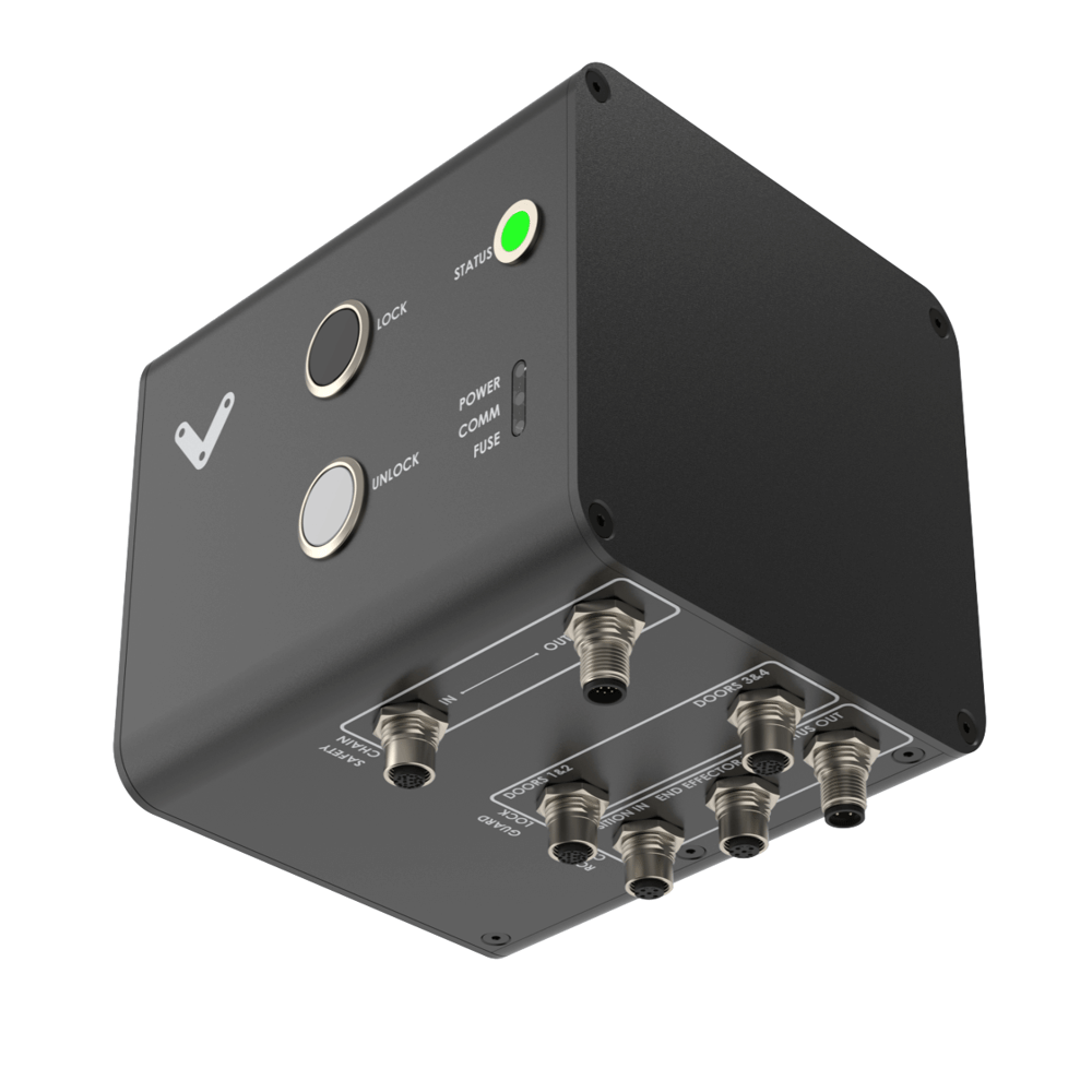
The Access Request Module, CE-SA-017-0001 is intended to interface up to 4 guard-locks and a MachineMotionV2. The minimum configuration is 1 guardlock and 1 MachineMotionV2.
Features
Compatible with MachineMotion V2
Configuration-free: plug & play
Modules can be daisy-chained
On-board LED for power, fuse, and communication status indication, located on the bottom of the module
LED indicator displaying power status, fault alerts, safety status, and activation of an emergency stop triggered by the module
The access request module can be connected to up to 4 guardlock devices but only one of high duty (1 opening per hour).
Included cables
1x Safety Extension cable (5m) - CE-CA-102-5000__3
1x Dry Contact Jumper - CE-JP-000-0002
2x Safety Jumper - CE-SA-102-0001
2x Guard Lock T-Splitter - CE-SA-124-0001
Important Notes
Safety
.png)
The Access Request Module performs safety functions as a part of a whole installation or machine. A complete safety system normally includes sensors or input units, logic units and contactors or output units. The manufacturer of the installation or machine is responsible for ensuring proper functioning of the whole system. The total concept of the control system into which the Safety Module is integrated must be validated by the user. Vention cannot guarantee all specifications of an installation or a machine without being responsible for the risk assessment and the design of the safety system. Vention takes over no liability for recommendations which are given or implied in the following description.
The following items must be taken into consideration during the design, risk assessment & installation of the safety system:
The Safety Module shall not be put into operation only after the safety functions have been tested during the commissioning.
The use of the Safety Module does not prevent the automatic reset of devices connected to the Safety OUT port.
The use of the Safety Module does not prevent the automatic start of the devices connected to the Safety OUT ports. According to EN IEC 60204-1:2018 and EN ISO 10218-1:2011 it is not allowed to restart automatically after emergency stop. Therefore the control systems of the connected devices have to disable the automatic start after emergency stop.
Opening the Safety Module or implementing unauthorized changes voids any warranty.
.png)
Functional error! Danger to life, risk of serious injuries or property damage
The Smart Access Request Module may only be connected to the equipment listed in this manual;
The Smart Access Request Module does not monitor the input redundant signals at the End Effector IN and Position IN ports. If the connected device at the Position IN port does not have monitoring of its output signals, the performance level of the safety function can be reduced;
If the a jumper is used for the Position IN port but a limit switch is connected to the End effector IN port, the performance level of the safety function can be reduced;
If devices with OSSD signals are connected to the both Position IN and End Effector IN ports, the device connected in the End Effector IN port shall accept OSSD inputs and be placed in cascade using the pins 1 and 3 as OSSD inputs;
As per ISO/TR 24119:2015, only 1 guardlock shall be high duty (opening the guardlock at a frequency greater than 1 per hour);
A maximum of 4 guardlock should be connected to maintain the performance level of the module;
Bypassing the guardlock with the Manual override may expose the operator to residual risk (heavy boxes in grippers, robot in wrong position);
The Smart Access Request Module is designed to operate in indoor environments without dust or high humidity. Dust and dampness may lead to malfunction. Do not install or operate the Safety Module outdoors.
Important Information
Shorting or overloading the guardlock port could trip the E-FUSE. To reset the fuse, a power cycle is needed.
As per ISO/TR 24119:2015, only 1 guardlock shall be high duty (opening the guardlock at a frequency greater than 1 per hour).
Bypassing the guardlock with the Manual override may expose the operator to residual risk (heavy boxes in grippers, robot in wrong position)
Technical specs
General Specifications
Item | Specification |
|---|---|
Part Number | CE-SA-017-0001 |
Weight | 0.8kg |
Dimensions | 19.0 x 15.0 x 9.0mm |
Material |
|
Operating Temp | 0 to 40°C |
IP rating (IEC 60529) | IP54 |
Electrical Specifications
Item | Specification |
|---|---|
Nominal input voltage | 24 VDC (Class 2 or SELV power supply* |
Input voltage range | 19.2 ~ 26.4 VDC |
Operating power consumption |
|
Short circuit protection | Internal E-FUSE IC |
Max current allowed | 2 A |
Post-short current | 250 mA |
Release delay at 24 V | < 40 ms |
** Note: In North America the Safety Module shall be supplied by a certified class 2 power supply. In Europe, the Safety Module must be supplied by an SELV circuit. When powered by the MachineMotion those requirements are met.
Physical Interface
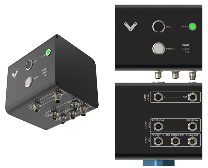 Figure 1: Physical Interface |
LED Indicators
Name | LED Color | Indicated (when ON) |
|---|---|---|
POWER | White | 24 VDC supplied to module |
COMM | White | EtherNet communication functional |
FUSE | Red | Module internal fuse tripped |
STATUS | Off | Disconnected |
STATUS | Green | Connected |
STATUS | White | Communication issue |
STATUS | Orange | Error |
STATUS | Red | E-Stop |
STATUS | Blinking Red | User triggered E-Stop |
STATUS | Blinking Blue | Processing |
Functionality
The Access Request Module enables guard lock devices to be interfaced with a MachineMotion safety chain. A guard lock is a device that prevents a user to open a door or gate based on a Safety or Programming condition. The Safety conditions to be met is the “Cell safe” input and the “end effector” input. Those conditions are optional meaning that if there is no residual risk involving an end effector in a cell, the end effector input can be jumped with the jumper CE-JP-000-0002. For the “Cell safe” input, it can be connected to a safe robot output or a fail safe inductive sensor CE-SN-010-0001.
Once everything is connected, software on the MachineMotion must be running in order to send the lock/unlock request. This was done to be flexible on the functionality. Pressing the buttons of the access request module sends a message to the MachineMotion. The MachineMotion can then send a request to lock/unlock the door. An alternate condition might be that an unlock request parks the robot in a safe location before unlocking the door.
In order for an access request to be successful, the cell must be in a safe state. Therefore, Access request Modules must be integrated into your application. See below for MachineLogic and MachineLogic Python examples.
Making a Lock or Unlock Request
The Access Request Module will accept requests to unlock under the following conditions:
Interlocks are detected on the guardlock port connectors
The guardlock is closed and locked
The Position IN port is triggered & End Effector IN port is untriggered
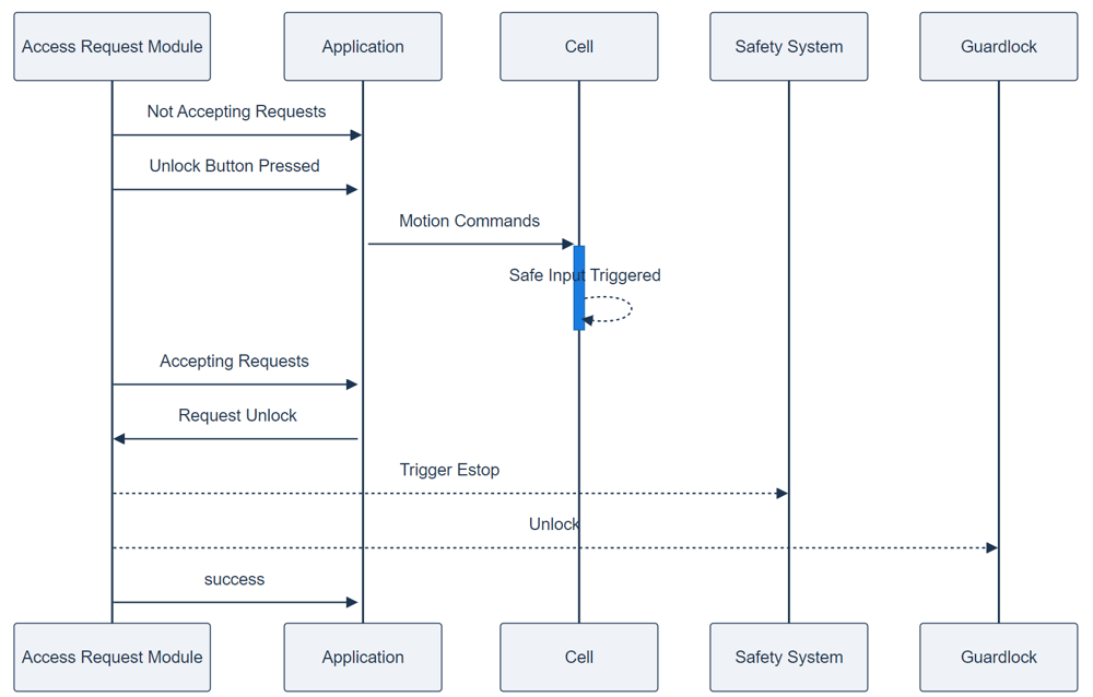 Figure 2: Successful unlock sequence |
The Access Request Module will accept requests to lock under the following conditions:
Interlocks are detected on the guardlock port connectors
The guardlock is closed and unlocked
The Position IN port is triggered & End Effector IN port is untriggered
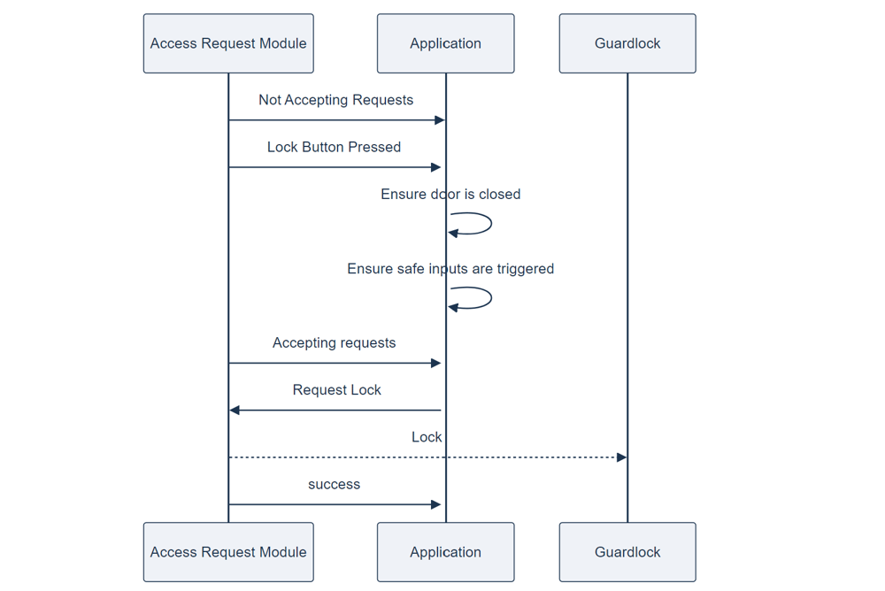 Figure 3: Successful lock sequence |
Port definitions
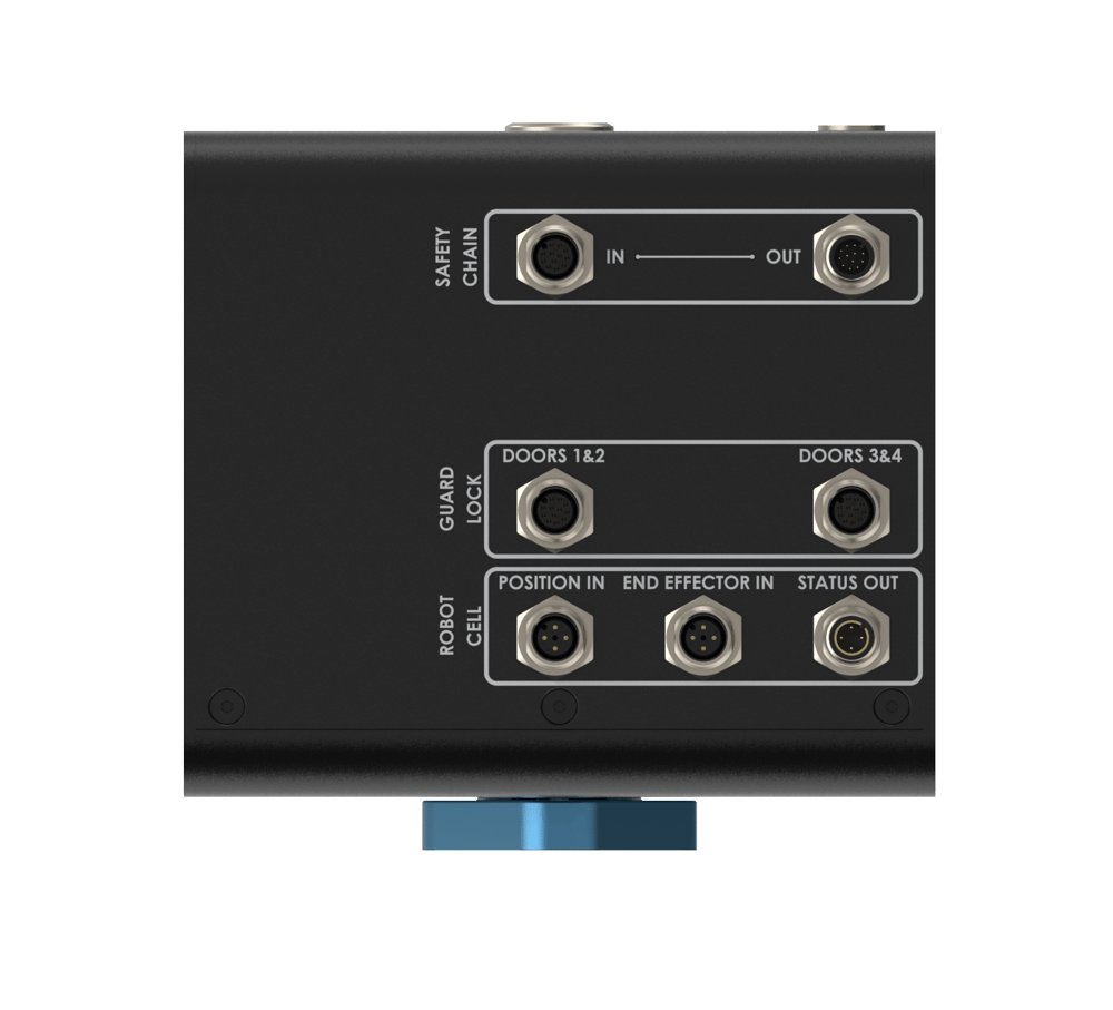 Figure 4: Access Request Module ports |
Safety OUT - Pin-out - M12, male, 12-pin, A-Keyed
The Safety OUT port connects to the SAFETY IN port of another Safety Module (if daisy-chaining multiple safety modules) or to a MachineMotion V2.
Pin | Function |
|---|---|
Pin 1 | 24 VDC |
Pin 2 | 0V |
Pin 3 | SAFETY OUT 11 |
Pin 4 | SAFETY OUT 12 |
Pin 5 | SAFETY OUT 21 |
Pin 6 | SAFETY OUT 22 |
Pin 7 | RESET +(24V) |
Pin 8 | RESET - (OUTPUT) |
Pin 9 | ETHERNET TX+ (auto-MDIX) |
Pin 10 | ETHERNET TX- (auto-MDIX) |
Pin 11 | ETHERNET RX+ (auto-MDIX) |
Pin 12 | ETHERNET RX- (auto-MDIX) |
Safety IN - Pin-out - M12, female, 12-pin, A-Keyed
The Safety IN port connects to the SAFETY OUT port of another Safety Module (if daisy-chaining multiple safety modules) or to an E-Stop and Reset Module (CE-SA-007-0000). IMPORTANT: If the SAFETY IN port is not used, insert the included yellow jumper.
Pin | Function |
|---|---|
Pin 1 | 24 VDC |
Pin 2 | 0V |
Pin 3 | SAFETY IN11 |
Pin 4 | SAFETY IN 12 |
Pin 5 | SAFETY IN 21 |
Pin 6 | SAFETY IN 22 |
Pin 7 | RESET +(24V) |
Pin 8 | RESET - (INPUT) |
Pin 9 | ETHERNET TX+ (auto-MDIX) |
Pin 10 | ETHERNET TX- (auto-MDIX) |
Pin 11 | ETHERNET RX+ (auto-MDIX) |
Pin 12 | ETHERNET RX- (auto-MDIX) |
Door 1 & 2 - Pin-out - M12, female, 12-pin, A-Keyed
Pin | Function |
|---|---|
Pin 1 | Lock signal A1 (24V fused) |
Pin 2 | 0V A2 |
Pin 3 | Guard lock contact 1&2 11 |
Pin 4 | Guard lock contact 1&2 12 |
Pin 5 | Guard lock contact 1&2 21 |
Pin 6 | Guard lock contact 1&2 22 |
Pin 7 | Gate Feedback 43 (24V) |
Pin 8 | Gate Feedback 44 (input) |
Pin 9 | NC |
Pin 10 | NC |
Pin 11 | NC |
Pin 12 | NC |
Door 3 & 4 - Pin-out - M12, female, 12-pin, A-Keyed
Pin | Function |
|---|---|
Pin 1 | Lock signal A1 (24V fused) |
Pin 2 | 0V A2 |
Pin 3 | Guard lock contact 3&4 11 |
Pin 4 | Guard lock contact 3&4 12 |
Pin 5 | Guard lock contact 3&4 21 |
Pin 6 | Guard lock contact 3&4 22 |
Pin 7 | Gate Feedback 43 (24V) |
Pin 8 | Gate Feedback 44 (input) |
Pin 9 | NC |
Pin 10 | NC |
Pin 11 | NC |
Pin 12 | NC |
Position IN - Pin-out - M12, female, 4-pin, A-Keyed
Pin | Function |
|---|---|
Pin 1 | 24V fused |
Pin 2 | OSSD input 1 |
Pin 3 | 0V |
Pin 4 | OSSD input 2 |
End Effector IN - Pin-out - M12, female, 4-pin, A-Keyed
Pin | Function |
|---|---|
Pin 1 | 11 |
Pin 2 | 12 |
Pin 3 | 21 |
Pin 4 | 22 |
Status OUT - Pin-out - M12, male, 4-pin, A-Keyed
Pin | Function |
|---|---|
Pin 1 | NC |
Pin 2 | OSSD output 1 |
Pin 3 | 0V |
Pin 4 | OSSD output 2 |
Mounting
Install the module mounting bracket (CE-HW-005-1002) to the extrusion with the screws provided (HW-FN-003-0018). Install the module onto the mounting bracket as illustrated below.
.png) Figure 5: Module Mounting | .png) Figure 3: Module Mounting |
Wiring Diagrams
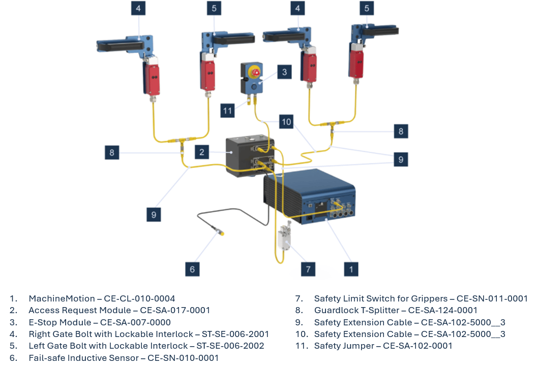 Figure 6: Access Request Module with 4 guardlocks |
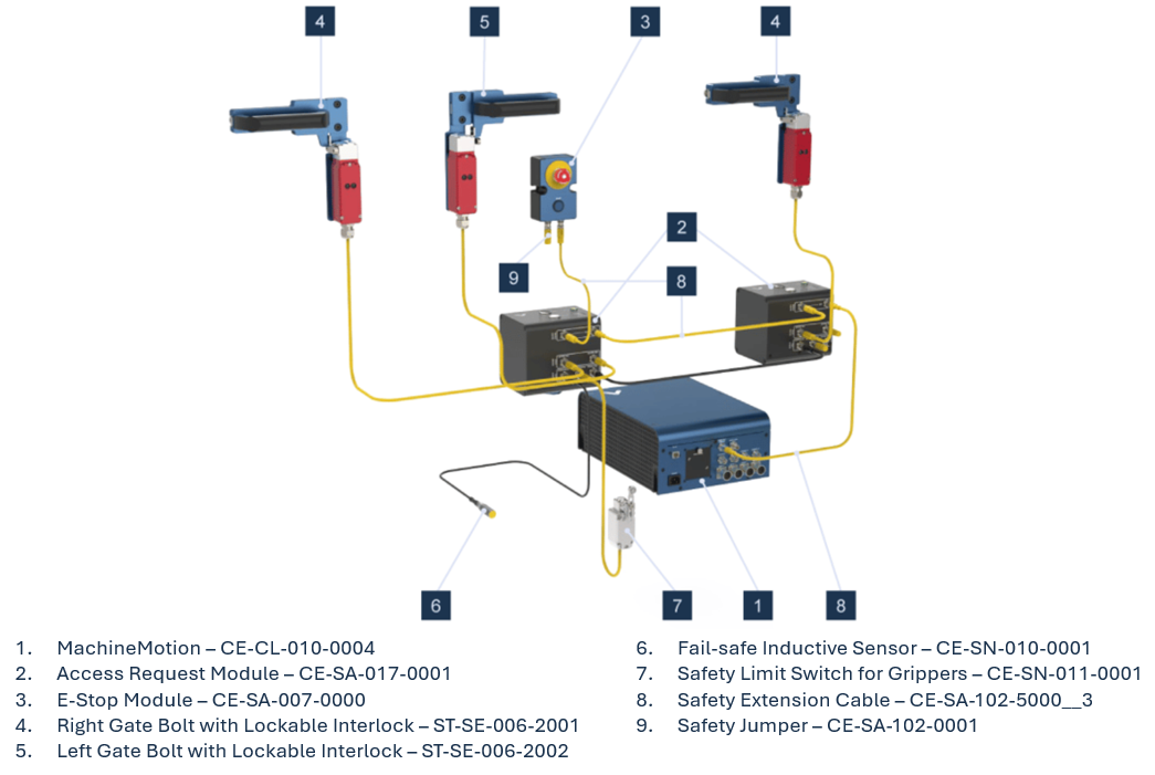 Figure 7: Daisy-chaining Access Request Modules |
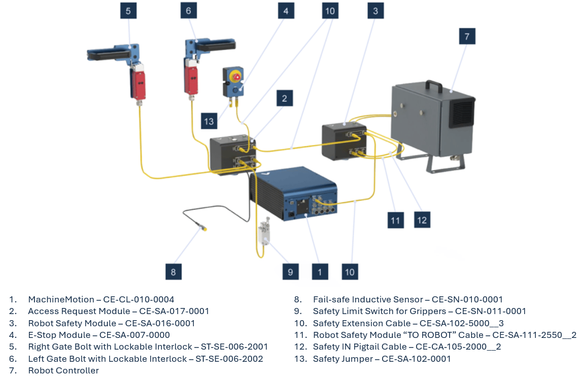 Figure 8: Access Request Module with Robot Safety Module |
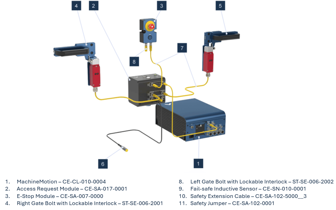 Figure 9: Access Request Module with 2 guardlocks |
*Note: Insert a black jumper into any unused input on this safety module for proper functionality. Yellow jumpers are reserved for unused safety ports on MachineMotion.
HTTP commands
The Access Request module can receive commands from HTTP to lock or unlock the doors. This enables a user to lock/unlock doors on events, like a push button press.
Route | Data Type | Format | Description |
|---|---|---|---|
| json |
| Will try to lock the doors on the target device |
HTTP /access-request return codes :
Code | Full json payload |
|---|---|
0 | {“code”:0,”msg”:”Success”} |
1 | {“code”:1,”msg”:”Post must be of JSON type with format {“serial-number”: INT, “command”: “lock” |
2 | {“code”:2,”msg”:”Smart Module not found.”,”errors”:[]} |
3 | {“code”:3,”msg”:”Smart Module not connected.”,”errors”:[]} |
4 | {“code”:4,”msg”:”Smart Module is not an Access-Request Module.”,”errors”:[]} |
5 | {“code”:5,”msg”:”Access-Request Module is not accepting requests. Topic not initialized.”,”errors”:[]} |
6 | {“code”:6,”msg”:”Access-Request Module is not accepting requests. Cell is not safe”,”errors”:[]} |
7 | {“code”:7,”msg”:”Access-Request Module is not accepting requests. Door is Open.”,”errors”:[]} |
8 | {“code”:8,”msg”:”door is already locked.”,”errors”:[]} |
9 | {“code”:9,”msg”:”door is already unlocked.”,”errors”:[]} |
10 | {“code”:10,”msg”:”Access-Request Module was unable to lock”,”errors”:[]} |
11 | {“code”:11,”msg”:”Access-Request Module was unable to unlock”,”errors”:[]} |
99 | {“code”:99,”msg”:”error”} |
MQTT topics
Device Type access-request
Topic | Data Type | Description |
|---|---|---|
| int (0 or 1) | 0 = disconnected, 1 = connected |
| string array | Array of string which indicates all current errors |
| int | Temperature of the device in celcius |
| int (0 or 1) | Status of the input voltage on safety-in port. |
| int (0 or 1) | Status of the output voltage on safety-out port. |
| int (0 or 1) | Indicates if a door is opened |
| int (0 or 1) | Indicates if doors are locked |
| int (0 or 1) | Indicates if the module accepts lock/unlock requests |
| int (0 or 1) | Status of the input of the IN and END port. Status out port. |
| int (0 or 1) | Status of the user request |
| int (0 or 1) | Status of the request |
| int (0 or 1) | Indicates if there’s a transition between lock and unlocked/unlocked and locked |
| int (0 or 1) | 0 = locked, 1= unlocked |
Error codes
Code | Errors | Description |
|---|---|---|
1 |
| shortcircuit, cross fault, or wrong feedback |
2 |
| shortcircuit, cross fault, wrong feedback, feedback not simultaneous |
9 |
| Door has a problem. Error in door signals / miswiring |
10 |
| shortcircuit, cross fault |
11 |
| Signals not simultaneous |
12 |
| shortcircuit, cross fault, or wrong feedback |
Integration in MachineLogic
For any use-case requiring the use of the Access Request Module with MachineLogic Code-Free programming, please contact integrationsupport@vention.cc
MachineLogic Python Unlock Sequence Example
Below is an example of how the Access Request Module can be used in MachineLogic Python applications.
from machinelogic import Machine, ActuatorGroup
from machinelogic import MachineException, MachineMotionException, ActuatorGroupException, ActuatorException, RobotException

### Configuration ###

# The following code has been automatically generated from the configuration.
# If the configuration changes, please update the code below, and ensure that the names match.

machine = Machine()

### Program ###

# Start coding here!
# Documentation can be found at vention.io/resources/guides/machinelogic-python-programming-514
import requests
from time import sleep

def request_access(machine_ip,module_serial_number, unlock = True):
    unlock_string = "unlock" if unlock else "lock"
    payload = {
      "serial-number": module_serial_number,
      "command": unlock_string
    }
    try:
        r = requests.post(
          "http://localhost:4446/access-request",
          json = payload
        )
    finally:
        return ( r.status_code == 200, r.text)

if __name__ == "__main__":

    m = Machine()
    ip = '192.168.7.2'
    serial_number = 1110003 # serial number can be found on device label

    def handle_module_status(topic, payload):
        print(topic, payload) # display incoming module statuses

    def handle_access_request(topic, payload): # callback for module button press
        print("handling request", topic, payload)
        if not payload: # button is released, do nothing
          return

        is_unlock_request = topic.split('/')[3] == "button-unlock"
        success, info = request_access(ip,serial_number,is_unlock_request)
        print(info)

    machine.on_mqtt_event(
      f'safety-module-hub/access-request/{serial_number}/button-lock',
      handle_access_request
    )

    machine.on_mqtt_event(
      f'safety-module-hub/access-request/{serial_number}/button-unlock',
      handle_access_request
    )

    machine.on_mqtt_event(
      f'safety-module-hub/access-request/#',
      handle_module_status
    )

    while True:
        sleep(1)
Safety Data
The Smart Access Request Module realizes the following safety functions:
System emergency stop output at the Safety OUT connector from the Safety IN port (E-stop_SafetyOUT);
Guardlock safety function without safe position input (GuardLock);
Guardlock safety function with safe position input (GuardLock_PositionIN).
For each of these functions, safety data can be found in the following tables. Due to potential fault masking, the safety data is dependent on the number of doors and their frequency of use.
The table below refers to the safety data with only one door or no door frequently used and up to 4 not frequently used doors:
Safety Function | PL | Cat. | MTTFd | DCavg | PFHd | Response time |
|---|---|---|---|---|---|---|
E-stop_SafetyOUT | e | 3 | 64 | 99% | 8.84E-08 | 20 ms |
GuardLock | e | 3 | 64 | 99% | 8.84E-08 | Not applicable |
GuardLock_PositionIN | e | 3 | 64 | 99% | 8.84E-08 | Not applicable |
The table below refers to the safety data with no door frequently used and up to 30 doors not frequently used doors or 1 frequently used doors and up to 4 not frequently used doors:
Safety Function | PL | Cat. | MTTFd | DCavg | PFHd | Response time |
|---|---|---|---|---|---|---|
E-stop_SafetyOUT | e | 3 | 64 | 99% | 8.84E-08 | 20 ms |
GuardLock | d | 3 | 64 | 91.3% | 2.13E-07 | Not applicable |
GuardLock_PositionIN | d | 3 | 64 | 91.3% | 2.13E-07 | Not applicable |
The above information have been calculated based on the following operation conditions:
Data | Value | Unit |
|---|---|---|
dop | 365 | days/years |
hop | 24 | hours/days |
tcycle | 8640 | s/cycle |