|
Manufacturing, assembly, and inspection fixtures share several common elements of design. The following guide covers the basic design principles that Vention uses for jigs and fixtures. This guide will discuss the various tool body options available, how to select the proper locators and locator end-tips for a specific application, and how to configure clamps and supports.
1. Design the tool body
The orientation of the workpiece which will be most appropriate for the application must first be determined. This orientation can be flat, angled, or vertical and is driven by considerations such as workpiece geometry, the type of operation being performed on the workpiece, and ergonomics.
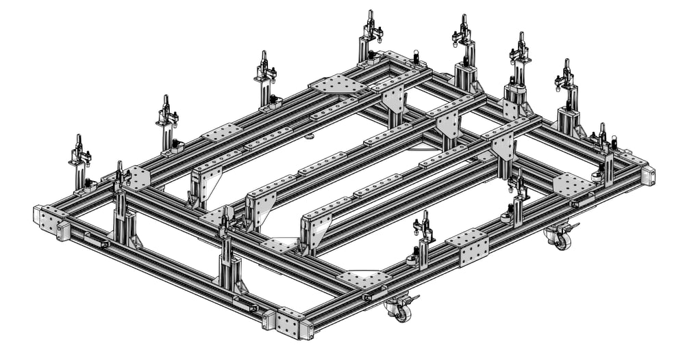
A tool body should use modular components which can be configured to the most appropriate orientation, such that the fixture can be reused for several workpieces as products evolve and manufacturing needs change. High-rigidity T-slot aluminum extrusions are an ideal choice for such a tool body design approach, and when used in combination with tooling plates, they allow for maximum flexibility and reconfigurability. Tooling plates typically consist of a metal plate which has been milled flat to a specific tolerance and threaded with multiple evenly-space holes (M8x1.25 thread with 22.5mm spacing is the Vention standard). Plain through holes are also drilled around the plate’s perimeter to mount the tooling plate to the tool body; these are counterbored such that they do not protrude above the plate surface. These threaded holes are used to add workpiece supports and later clamping mechanisms anywhere around the plate to accommodate various part geometries.
|
|
|
| |
|---|---|---|---|---|
Part number | ||||
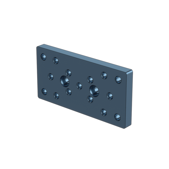
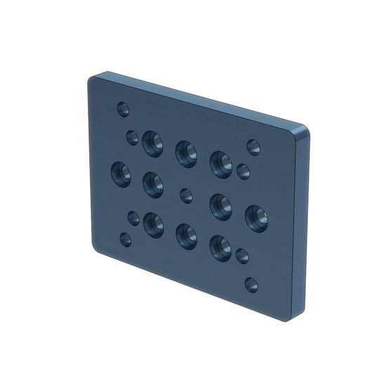
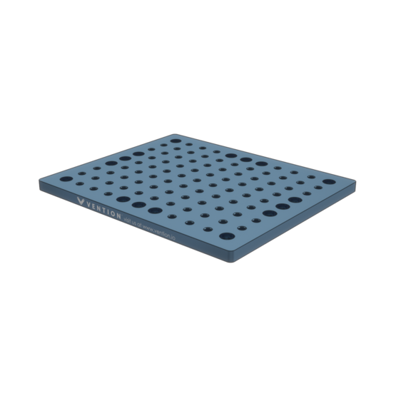
Description | 135x68mm Aluminum Mounting Plate | 135x100mm Aluminum Mounting Plate | 270x225mm Aluminum Tooling Plate | 540x450mm Aluminum Tooling Plate |
Mounting Compatibility | Tooling balls and rest buttons | Tooling balls and rest buttons | 83x M8 mounting holes on a 22.5x22.5mm grid pattern | 401x M8 mounting holes on a 22.5x22.5mm grid pattern |

2. Select locators
Once a solid base has been designed and part selection is finalized for the tool body and tooling plate, workpiece locators are added to the fixture. These will be used to precisely support the workpiece or provide a consistent reference point on the fixture and so must allow for position fine-tuning. For this reason, locators are usually considered according to the type of motion they provide, for example linear or rotational displacement (also known as polar displacement), and according to the level of precision that is achievable.
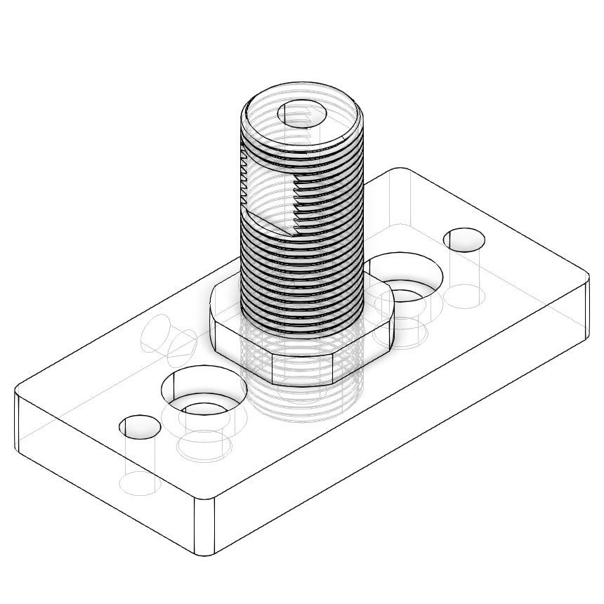
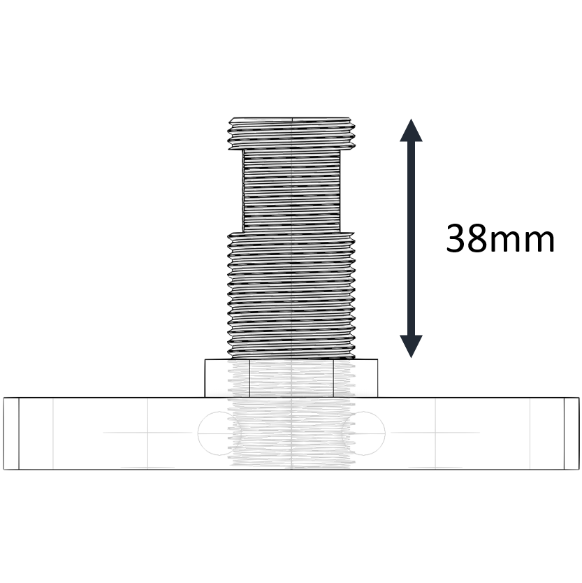
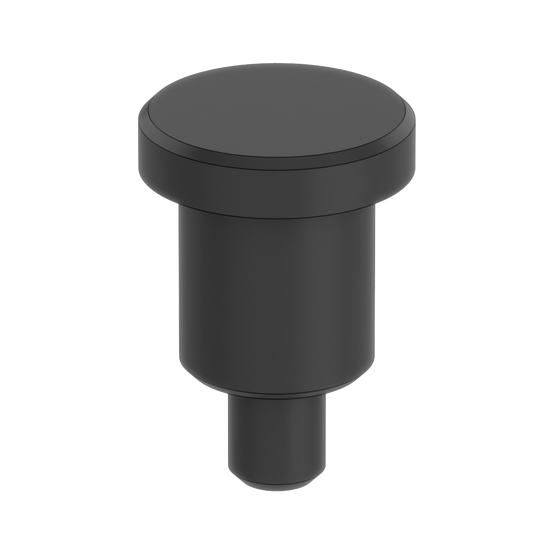
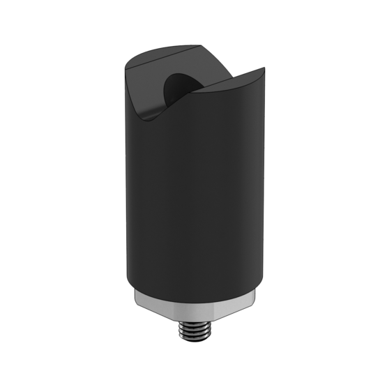
The simplest example are locators which provide a linear displacement along a single axis, such as Vention’s Height Locator (ST-SP-007-0008). This locator can provide up to 38mm vertical displacement with an accuracy of roughly +/- 0.2mm.
|
|
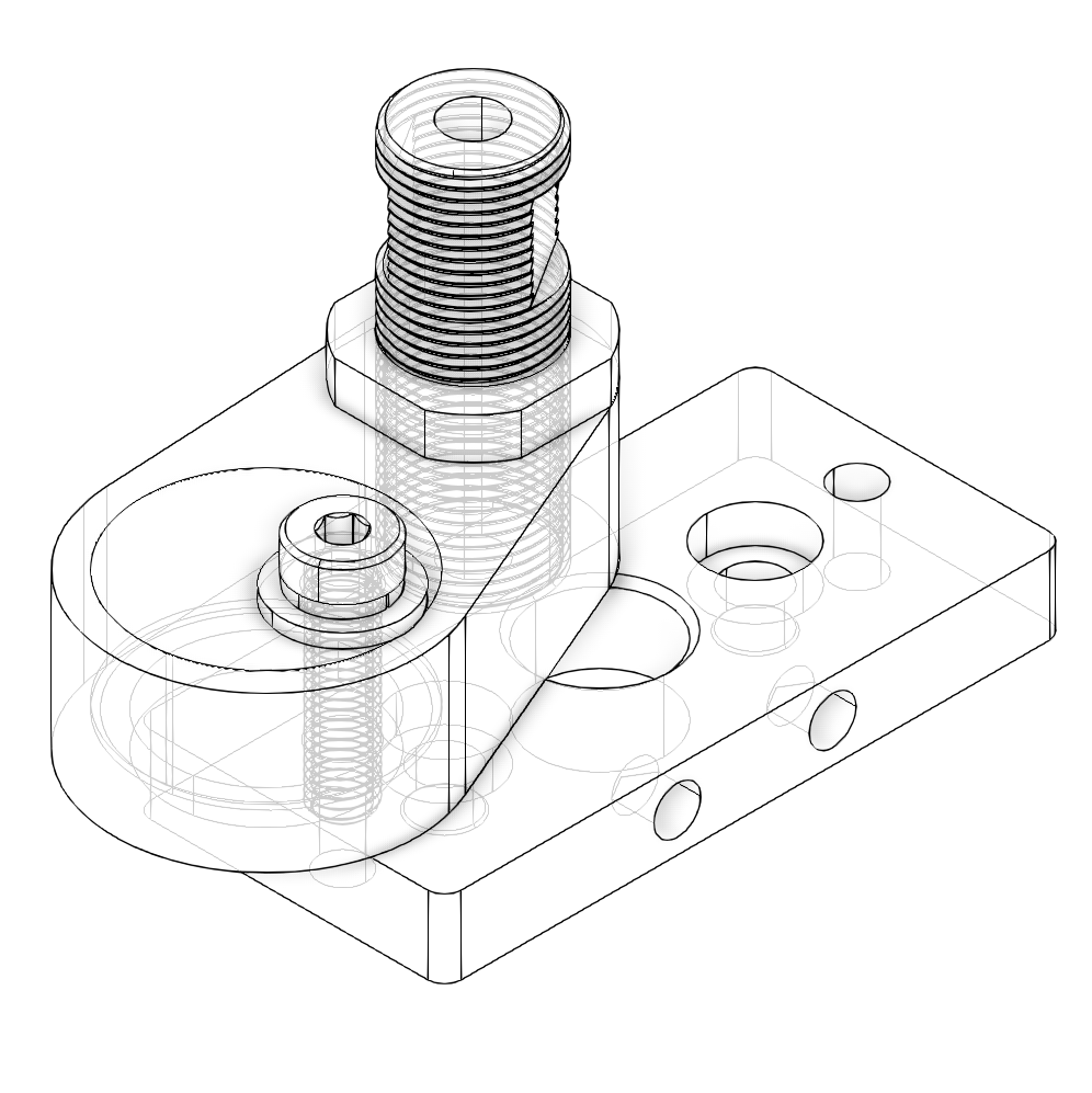
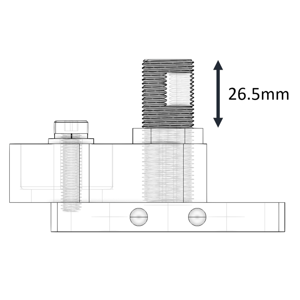
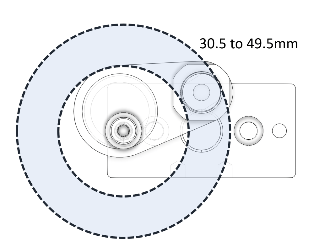
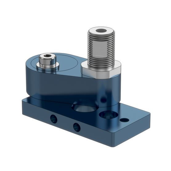
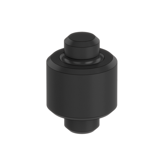
Another example are eccentric locators which allow for rough positioning within a plane through rotation of the locating feature around a fixed point. An example of this is Vention’s Eccentric Locator (ST-SP-007-0001) which combines linear and polar displacements. It allows for up to 26.5mm of Z vertical displacement plus a polar displacement covering a full 360 degrees at radii between 30.5 mm and 49.5 mm. The eccentric locator provides a simple and fast adjustment option when precision of +/- 0.5mm is acceptable.
|
|
|
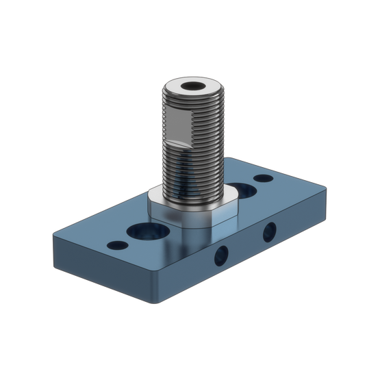
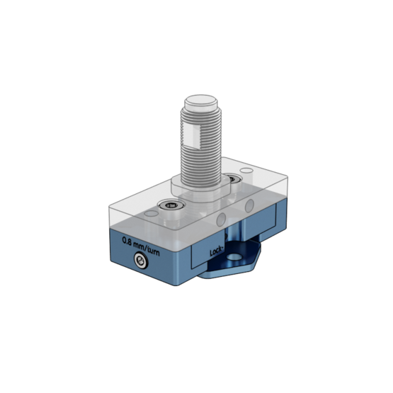
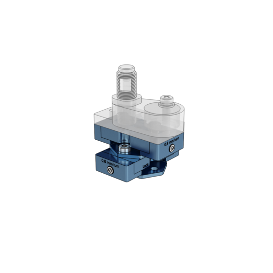
For more precision in the range of +/- 0.1mm, linear displacement type locators with finer adjustment mechanisms can be used such as Vention’s Single Stage X Locator (ST-SP-013-0001) or Double Stage XY Locator (ST-SP-013-0006). The single stage version features 22.5 mm of translational displacement paired with a pitch of 0.8 mm per full turn, resulting in a resolution of 0.1 mm by turning the displacement screw one eighth (⅛) of a turn.
|
|
|
|
|
| |
|---|---|---|---|---|---|---|
Part number | ||||||
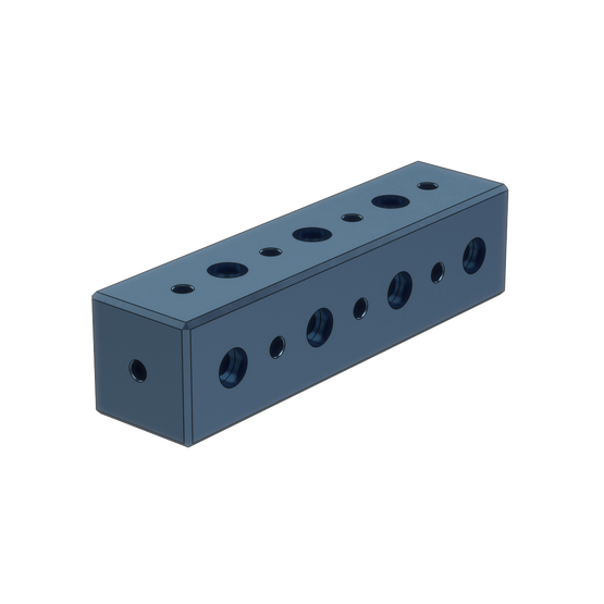
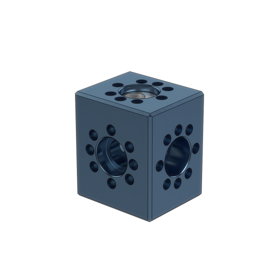
Description | Long mounting block | Eccentric mounting block | Eccentric locator | Height (Z) locator | Single Stage X Locator | Double Stage X-Y Locator |
Adjustment mechanism | n/a | Manual displacement of eccentric arm | Manual displacement of eccentric arm | M20 x 1.5 threaded rod and lock nut | M5 set screw, providing 0.8mm /turn | M5 set screw, providing 0.8mm /turn |
Positioning | n/a | ± 0.5mm | ± 0.5mm | ± 0.2mm | ± 0.1mm | ± 0.1mm |
Displacement in X | n/a | Radii of 4.5mm | Radii between 30.5mm and 49.5mm | n/a | 22.5mm | 22.5mm |
Displacement in Y | n/a | Radii of 4.5mm | Radii between 30.5mm and 49.5mm | n/a | n/a | 22.5mm |
Displacement in Z | n/a | n/a | 26.5 mm | 38 mm | n/a | n/a |
3. Select locator end-tips
Locator end-tips are the next consideration once locators have been selected. Once again, the type of end-tips or datum selected depends on the application and the reference planes on the workpiece. End-tips should be made of hardened metal so that they do not wear down with repeated use, which could negatively affect repeatability.
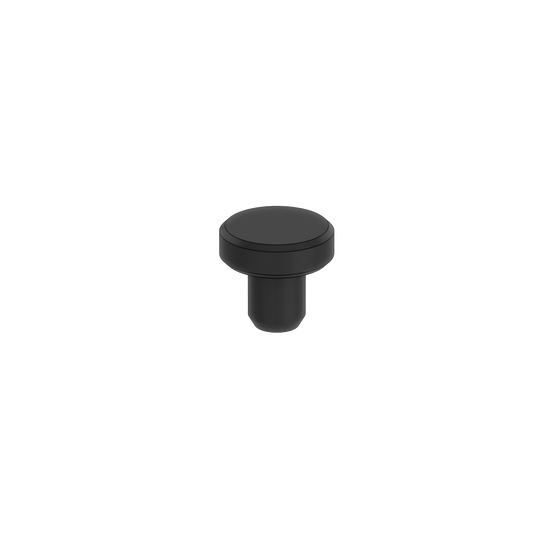
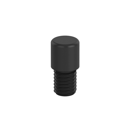
For components being located along the same XY plane (i.e., flat), simple rest buttons are acceptable such as Vention’s Rest Buttons (HW-RP-001-0001 & HW-RP-001-0003) or Shoulder Rest Buttons (HW-RP-001-0005). Since each of these three rest button end-tips features a flat surface, a plane can established by placing them at the same height.
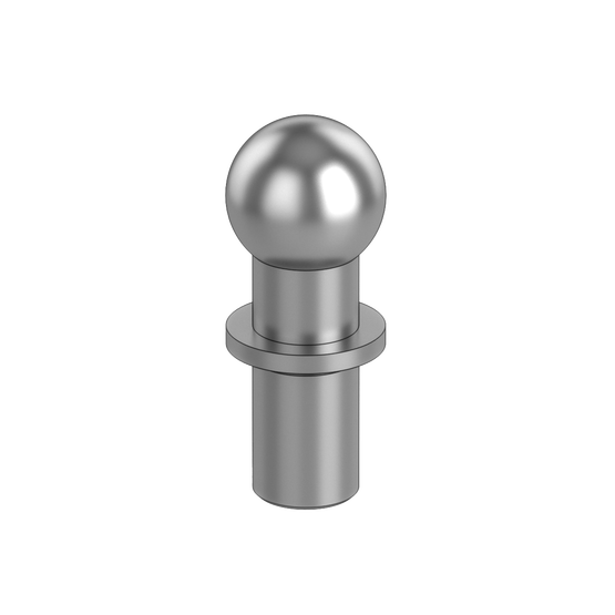
For applications that require a datum for a surface part, it is recommended to use tooling balls, for example Vention’s 12-mm and 20-mm Tooling Balls (HW-RP-001-0002 and HW-RP-001-0004). Tooling balls in contact with the surface of the workpiece present a single spatially defined point of contact, which means that two defined points describe a line, and three defined points describe a precise plane. Tooling balls can also be used as a reference point for inspection jigs when used in conjunction with a Coordinate Measuring Machine (CMM).
For supporting edges, it is recommended to use locators with a V-shape, for Vention’s V-Block Locator (HW-RP-004-0001). These V-Blocks feature a 90-degree cut out with a 5mm relief radius in the base of the V. This presents a perfect resting groove for an array of parts. Since the V-Block locator is made of nonabrasive black acetal, finished parts can be handled without incurring scratches. The V-Block locator also allows for +/- 8mm of height adjustment.
Similarly, Vention’s Threaded Locating Pin (HW-RP-003-0001) is also made of non-abrasive black nylon and can be used for edge positioning of a workpiece. This type of locating pin is often used for custom tray configurations in machine tending applications.
|
|
|
|
|
|
| |
|---|---|---|---|---|---|---|---|
Part number | |||||||
Application | Flat datum positioning | Flat datum positioning | Edge & flat datum positioning | Surface datum positioning | Surface datum positioning | Edge datum positioning | Edge & circular datum positioning |
Material | Hardened 1045 steel with black oxide finish | Hardened 1045 steel with black oxide finish | Hardened 1045 steel with black oxide finish | Hardened AISI 1144 steel | Hardened AISI 1144 steel | Black nylon | Black acetal |
Assembly | Transition fit | Transition fit | Transition fit | Transition fit | Transition fit | Threaded M8 x 1.25 | Threaded M8 x 1.25 with 8mm of vertical adjustment |

4. Select clamps
Next is to select clamps to securely hold the workpiece. At this stage in the design process, the workpiece is oriented as required and adequately supported so that it does not deform, but only the influence of gravity on its mass is holding in place. Most often, the jig/fixture must be lifted into a machine or will be worked on with force, each of which could dislodge the workpiece.
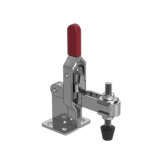
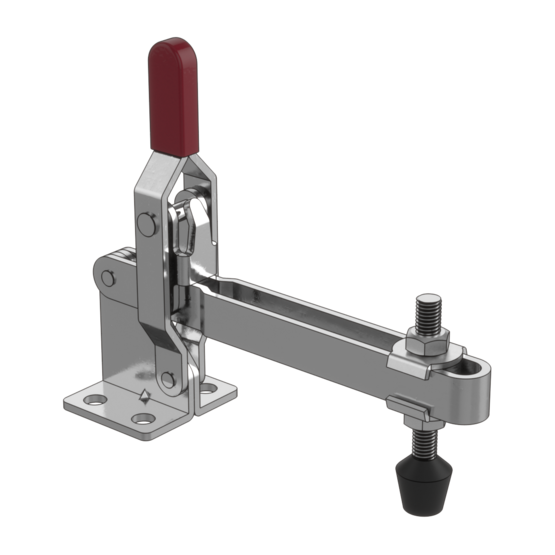
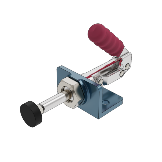
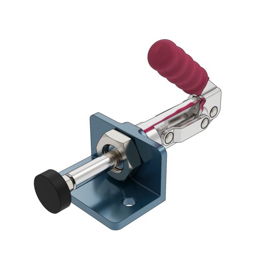
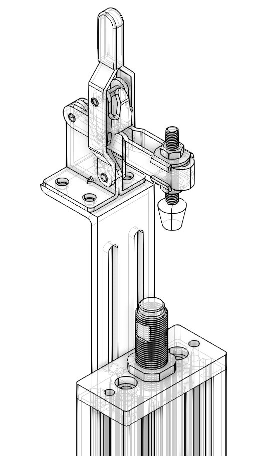
Clamps mounted on the fixture are the most common method to hold workpieces in place. Their pads exert a force on the workpiece and the friction between them ensures nothing will shift around. Examples of these are Vention’s 63-mm or 125-mm Toggle Clamps (HW-CP-001-0001 & HW-CP-001-0002) or Vention’s Push/Pull Toggle Clamps (HW-CP-003-0001 and HW-CP-003-0002). Toggle action is an ergonomic way to quickly mount and dismount, although for larger forces or more accurate applications, other clamp types exist. Part geometry constraints and desired clamping orientation determine are the main factors which determine which clamp to use.
|
|
|
| |
|---|---|---|---|---|
Part number | ||||
Pad type | 13mm diameter, soft rubber | 13mm diameter, soft rubber | 25mm diameter, soft rubber | 25mm diameter, soft rubber |
Adjustability | ± 63mm arm length | ± 125mm arm length | ± 32mm arm length | ± 32mm arm length |
If a significant force is being applied on the workpiece such that it could be temporarily deformed or permanently damaged, it is critical that side of the workpiece opposite the clamp is adequately supported by a locator. It is typical to find locators, locator end-tips, and clamps used all together to achieve this.
|
Vention’s library of modular parts for jigs and fixture is constantly expanding. More specialized parts, including parts from our partner Carr Lane, can be found here.
Need help to jump start your next jig and fixture project? Get in touch with an application specialist at support@vention.cc.