General Assembly
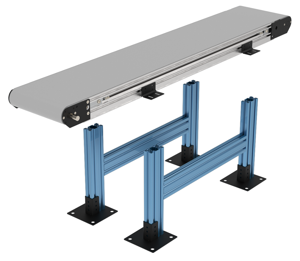
1. Assemble the Vention extrusion frame.
2. Install the Vention Belt Conveyor Mounting Brackets to the T-slot on the Dorner Conveyor using the included T-bar and M6 fasteners. Tighten using your fingers only.
|
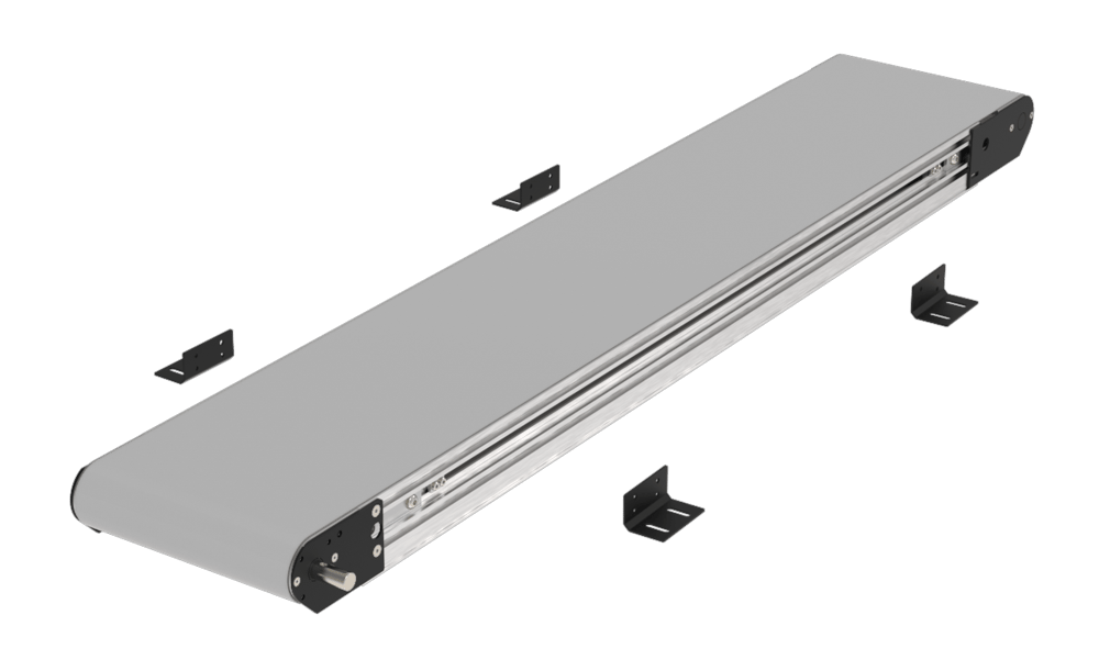
3. Mount the conveyor onto the extrusion frame and connect the brackets to the extrusions using the included M8 fasteners. Once the conveyor is mounted in place, tighten the brackets which connect to the conveyor.
|
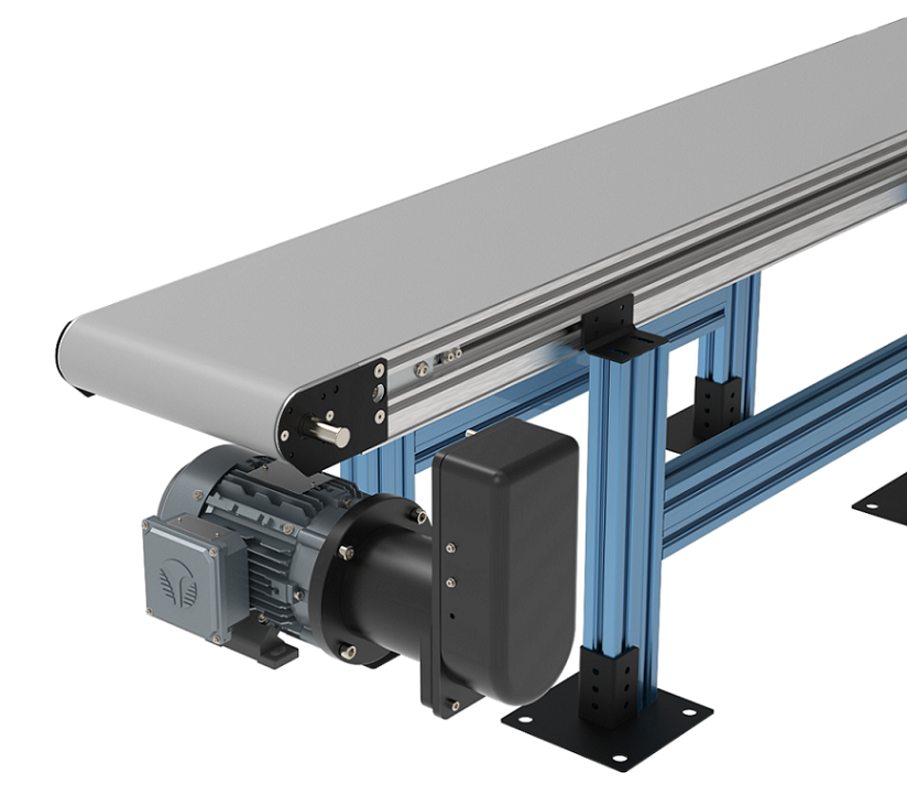
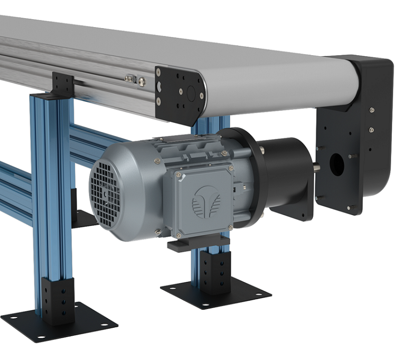
4. Install the motor gearbox and motor mount to the input shaft of the belt conveyor.
Note: when installing motors, apply a small amount of grease to the motor shaft so that it is lightly coated. This will reduce the possibility of fretting corrosion occurring during operation, making future removal easier.
|
Installing the motor mount
Required Tools:
Hex key wrenches: 2 mm, 2.5 mm, 3 mm, 5 mm
Straight edge
Torque wrench
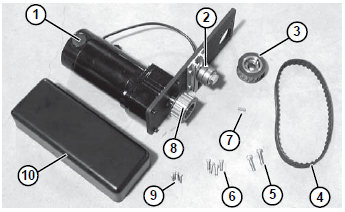
Installation Component List:
Bottom Mount Drive Assembly
Tensioner
Driven Pulley
Timing Belt
M8 Socket Head Screws (2x)
M6 Socket Head Screws (4x)
Key
Drive Pulley
Cover Screws
Cover
1-Typical components:
|
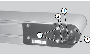
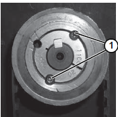
2-Locate drive output shaft (item 1). Remove two (2) M8 screws (item 2) and four (4) M6 screws (item 3) and discard. (figure below)
|
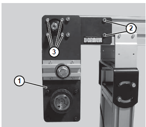
3- Attach bottom mount drive assembly (item 1) with two (2) M8 screws (item 2) and four (4) M6 screws (item 3). Tighten M6 screws to 146 in−lbs (16.5 N−m) and M8 screws to 288 in−lbs (32.5 N−m). (figure below)
|
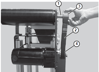
4- Install key (item 1, figure below)
5- Wrap the timing belt (item 2) around the driven pulley (item 3) and drive pulley (item 4). Install driven pulley onto conveyor shaft. (figure below)
|
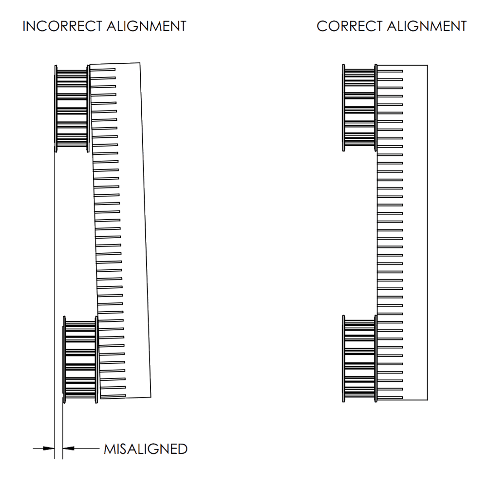
6- Using a straight edge (item 1), align the driven pulley (item 2) with the drive pulley (item 3).
|
|
7- Tighten driven pulley taper-lock screws (item 1).
|
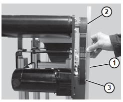
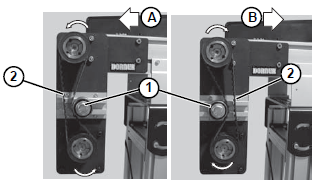
8- Depending on conveyor belt travel (direction A or B), locate the timing belt tensioner (item 1) as shown. Tension timing belt to obtain 1/8 inch (3 mm) deflection for 6 lb (3 Kg) of force at timing belt midpoint (item 2). Tighten the tensioner screw to 110 in-lb (12 Nm).
|
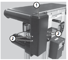
9- Install cover (item 1) with four (4) screws (item 2). Tighten screws to 35 in-lb (4 Nm).
|
Installing the transfer plate
1) Transfer plate for the drive tail of the conveyor:
|
To install the drive tail transfer plate, remove the four countersunk M6 screws in the conveyor end plate, and replace the transfer plate with the end plate. Now use the four M6 countersunk screws to install it. For installing the drive tail transfer plate on the drive side of the conveyor, place the transfer plate before installing the motor mount and spacer plate. Then, use the four M6 socket head cap screws and 2 M8 socket head cap screws that come with the motor mount to fasten the motor mount on top of the transfer plate and spacer plate.
|
|
2) Transfer plate for the idler tail of the conveyor:
The transfer plate for the idler tail of the conveyor is installed at the idler end of the conveyor (conveyor end without the motor mount).
|
To install the transfer plate for the idler tail, remove the two M5 countersunk in the conveyor end plate and then remove the end plate. Replace it with the transfer plate and fasten it with the same M5 countersunk screws.
Installing the AC motor, gearbox and VFD kit
Safety
Important: Take the following safety precautions when doing any maintenance:
Never work on energized equipment.
Always establish the motor connection first before energizing the VFD.
Routinely inspect the motor and gearbox to ensure all bolts are tightened properly.
Mounting the motor gearbox
The motor-gearbox combination comes pre-assembled.
To mount the motor:
Apply a small amount of grease to the gearbox output shaft.
Using the four M6 bolts and washers (provided), attach the gearbox to the conveyor drive input. Ensure the bolts are tightened adequately.
|
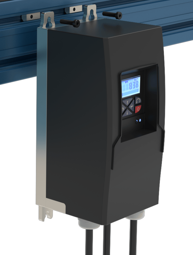
Mounting the VFD
The VFD supplies the motor with power and controls its speed. MachineMotion can communicate with the VFD and control up to three digital inputs, such as the VFD start-stop function, via the digital IO module.
To mount the VFD:
Select the placement area. Choose a dry place, like the side of the structure supporting the conveyor. Leave 150 mm of clearance below the VFD for its electrical cables, and ensure the VFD is within reach of the 2.5 m-long motor power cable.
Attach the VFD with the 2 provided M5 T-nuts and bolts. Insert them along the same horizontal t-slot. The fasteners are slightly long, so they can extend from the t-slot and serve as a perch to hook the VFD in for easy
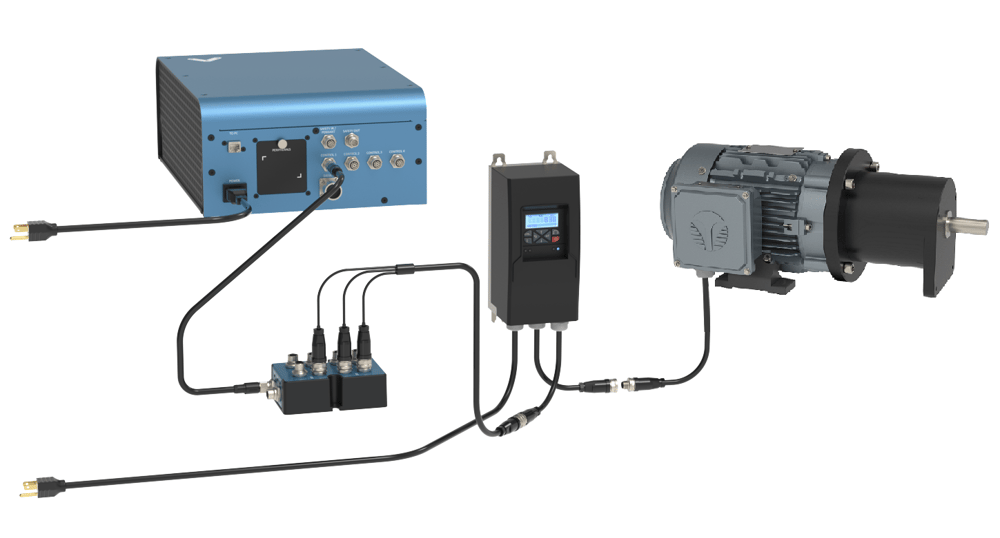
Connecting electronics
Internally, both the AC motor and VFD come pre-wired and configured for basic motor operations. To complete the electrical installation, follow the wiring diagram below:
|
Controlling and programming the VFD
The Lenze VFD is an extremely feature-rich frequency drive allowing for highly configurable control and motor operation. This is possible through modifying and configuring so-called parameters. Parameters are values, stored in the VFD, that control how the motor and VFD behave. Most of the parameters needed for basic function are pre-set and do not need changing.
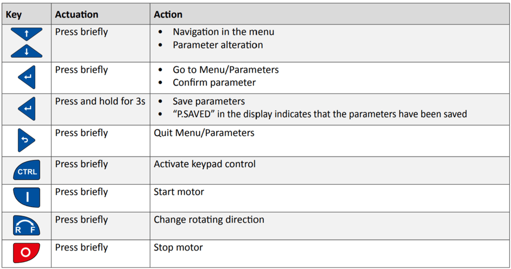
You can perform operations using the VFD keypad, as described in the table below.
|
However, you may need to manually configure some parameters if you are modifying motor operating characteristics or setting up certain digital inputs.
To change a parameter:
Press Enter briefly.
With the up and down arrow keys, select the group the parameter is in. Parameters are formatted as PXYY.ZZ, where the first digit after P indicates the group. (For example, parameter P400.01 is in group 4.) Press Enter.
With the up and down arrow keys, select the parameter. Press Enter.
With the up and down arrow keys, change the parameter value. Press Enter to input the change.
To save the new parameter value, press and hold Enter for at least three seconds.
Caution: Incorrect parameters can damage the motor or VFD.
Starting and stopping the motor
You can control the motor directly from the VFD - which is the default, manual option or through MachineMotion, which requires further integration.
Enabling VFD keypad control
Press CTRL briefly. The screen displays ”Keypad Full CTRL?” and then indicates the desired state (e.g.: “ON” will be displayed as the desired state).
Press Enter briefly to change from OFF to ON. A red error light will begin to flash when keypad control is enabled, this is normal.
Control via VFD keypad
To control the motor directly from the VFD, press the following buttons:
(I) key. Start motor, press briefly.
UP and DOWN arrow keys. Change frequency (motor RPM). There is no direct RPM feedback.
R-F key. Change directions.
(0) key (in red). Stop motor.
Control via MachineMotion
To control the motor remotely via MachineMotion, you will need to set up remote triggering of digital inputs (such as a start-stop function). This requires a MachineMotion, the Digital IO Module (CE-MD-001-0000__2) and Tower Light Cable, seen as the triple splitter cable above (CE-CA-051-5000), sold separately.
The following step-by-step guide will run through the example of setting up the “start-stop” and “forward-reverse” digital inputs:
Establish the connection of the Digital I/O module to the MachineMotion via any of the four available control ports.
Connect the triple splitter cable as follows:
Connector labelled Red to Digital Output 0 (start-stop trigger)
Connector labelled Blue to Digital Output 1 (reverse trigger)
Connector labelled Green is not used
Establish the connection with the splitter cable to the VFD as seen above.
With the VFD keypad control enabled, navigate to parameter menu P210.00, which is the minimum motor frequency. It is natively set to 0 Hz, however will be required to be set at the desired operating frequency. Set the desired value using the UP and DOWN arrow keys and press Enter once the desired value is achieved.
Return to the main menu and disable keypad control. Note the displayed text on the screen indicating “KSTOP”.
Press the motor start button (I). It should now read “STOP”. You are now ready to control the VFD from MachineLogic.
In MachineLogic, under Manual Control, enable Digital Output 0, the motor should spin up to the previously set frequency.
With Digital Output 0 still triggered, enable Output 1, the motor should decelerate and reverse direction back up to the previously set frequency.
For a list of additional available digital inputs and a step-by-step programming guide, see Lenze’s i510 commissioning guide, section 6.2: lenze.com.
If you have any questions or concerns about configuring VFD parameters, Vention’s customer success team can assist you.