Overview
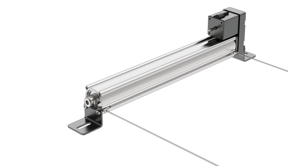
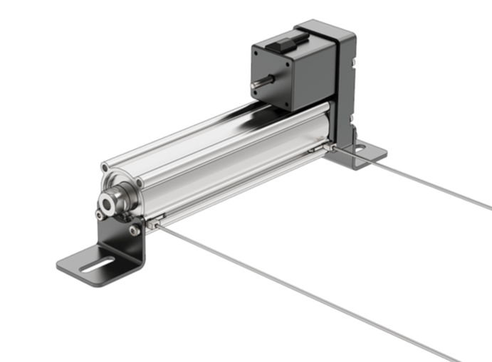
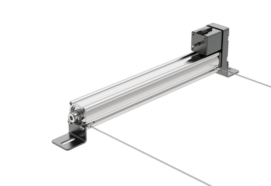
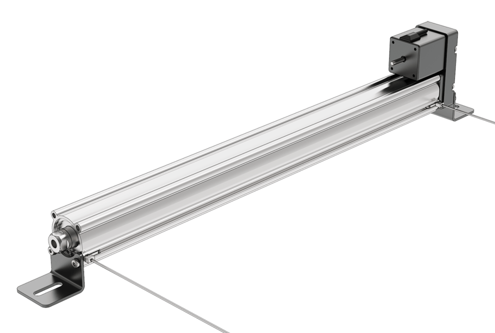
The electric cylinder actuator is a fully enclosed actuator based on a leadscrew mechanism. When the NEMA 17 motor rotates, the motion is transferred through the mechanism and converted to linear motion by the leadscrew which causes the protruding shaft to move in and out of the front face depending on the motor rotation direction. The use of a stepper motor allows for easy plug-and-play with the Vention MachineMotion 2 controller and offers complete position, speed, and acceleration control.
|
Applications
Electric cylinders have a wide range of applications, from pneumatic or hydraulic actuator replacement for those who do not want to run a pneumatic or hydraulic system, to high precision positioning systems. Check out our public library for inspirations on how to integrate an electric cylinder within your design!
Technical Specifications
The electric cylinders are available in 3 lengths: 100mm stroke, 250mm stroke, and 400mm stroke. All 3 actuators are powered by the same NEMA 17 motor and they all share the same lead pitch. For this reason, the data shown below is common to all three models, with the stroke length being the only variable. Each actuator also includes two pre-installed reed switches that are wired to an M12 4-pin connector and act as either a home or end of travel sensor.
MO-EC-001-0100__2 | MO-EC-001-0250__2 | MO-EC-001-0400__2 | |
|---|---|---|---|
Displacement Ratio (mm/turn) | 6 | 6 | 6 |
Stroke Length (mm) | 100 | 250 | 400 |
Max Force (N) | 255 | 255 | 255 |
Max Speed (mm/s) | 200 | 200 | 200 |
Precision (mm) | ± 0.02 | ± 0.02 | ± 0.02 |
Assembly Instructions
The electric cylinders come with two sheet metal brackets. These brackets can be attached to Vention extrusions or plates using M8 X 16mm fasteners and T-nuts as required. The end of the electric cylinder push rod is a female M8 X 1.25 thread. It is possible to attach other Vention parts such as the Pneumatic and Electric Actuator Push Block using the provided M8 X 20 fastener.
The motor cable provided with the electric cylinder has 4 ends: one end that connects to the MachineMotion 2 controller, one end that connects to the motor (already connected out-of-the-box) and 2 ends for the position sensors. Once the actuator is installed:
Connect the Sensor A cable end to the sensor closest to the shaft opening.
Connect the Sensor B cable end to the sensor furthest away from the shaft opening.
Finally connect the motor cable to the MachineMotion 2 controller to begin operation.
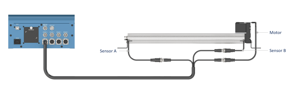
Electric Cylinder wiring with the MachineMotion 2 controller
If one wishes to not use one or both reed switches as position sensors, connect the cable end to one of 2 the provided sensor jumpers CE-JP-000-0000.
Configuration and position sensors setup
Note that the NEMA 17 motor is rated to operate at a maximum of 1.68A so the associated motor driver should be set to a limit of 1.5A to ensure motor longevity.
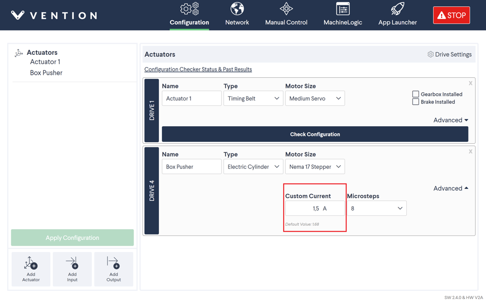 Setting the maximum motor current to 1.5A |
Also note that the maximum speed the motor can reach without stalling is 200mm/s.
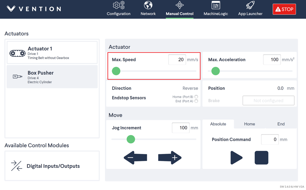 Setting the maximum motor speed to 20mm/s |
Position sensors can slide along the groove of the electric cylinder and their position can be fixed by tightening the set screw. Sensor A gets triggered when the electric cylinder shaft is fully extended while sensor B gets triggered when fully retracted. Depending on the motor direction, sensors A and B will each correspond to either the Home position or the End position. Motor direction can be configured in the Configuration page, inside the Drive Settings menu.
Motor direction | Sensor A (shaft fully extended) | Sensor B (shaft fully retracted) |
|---|---|---|
Normal | Home position | End position |
Reverse | End position | Home position |
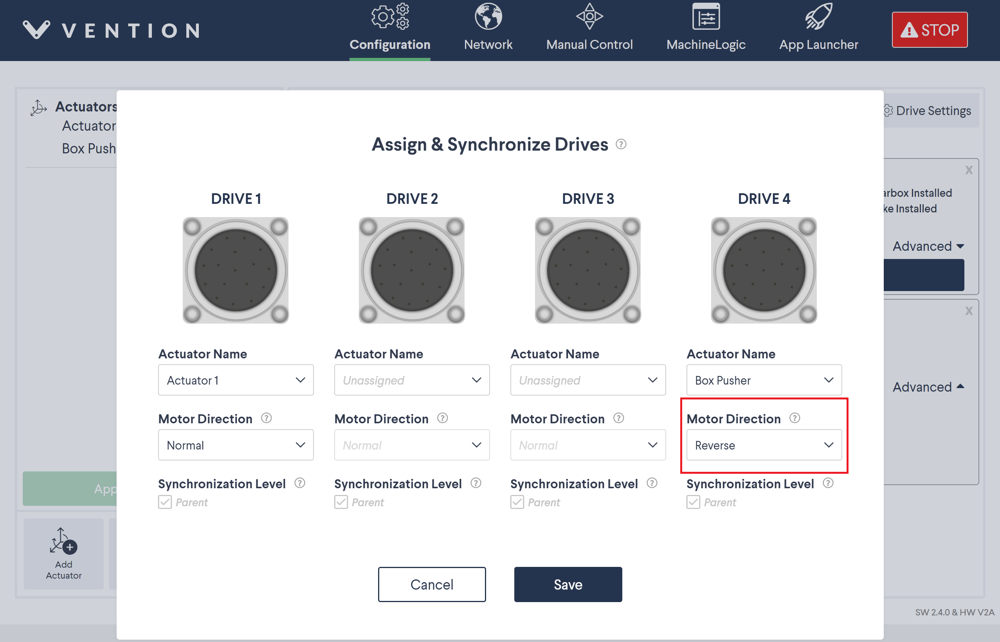 Configuring the motor in reverse direction |
Once the motor direction has been chosen and set, follow these steps to set up the position sensors:
Fix the sensors in their most extreme positions: sensor A at the end of the electric cylinder closest to the shaft opening, sensor B at the other end furthest away from the shaft opening.
Jog the electric cylinder actuator so that the shaft is fully extended (the motor should be heard stalling).
Slide sensor A away from the shaft opening. When the red indicator LED turns off, fix the position of the sensor.
Jog the electric cylinder actuator so that the shaft is fully retracted (the motor should be heard stalling).
Slide sensor B towards the shaft opening. When the red indicator LED turns off, fix the position of the sensor.
Jog the electric cylinder actuator back and forth between the Home and End position and make sure the actuator stops when the corresponding sensor gets triggered.