Overview
Use this technical document as a guide to select your belt conveyor size and power transmission to ensure that you purchase the correct combination of components for your application. This document will outline how to calculate the required forces to transfer your products as well as the corresponding powertrain combinations to meet those requirements.
Applications
Applications for belt conveyors are diverse, but at their core, a belt conveyor is always used to move an object from position A to position B. Applications vary from simple conveying systems to complex pick-and-place systems with indexing and part accumulation.
Check out our design library in the link below for inspiration.
Technical Specifications
Gearbox Ratio | 8:1 | 10:1 | 15:1 |
|---|---|---|---|
Rated Non-Accumulated Payload Pulling (kg)* | 45 | 75 | 125 kg up to 366 mm/s |
Rated Non-Accumulated Payload Pushing (kg)* | 45 | 60 | 60 |
Rated Accumulated Payload Pulling (kg)* | 23 | 33 | 50 |
Rated Accumulated Payload Pushing (kg)* | 23 | 30 | 30 |
Displacement Ratio (mm/turn) | 30 | 24 | 16 |
Belt Speed range (mm/s) | 215 - 860 (mm/s) | 172 - 688 (mm/s) | 115 - 459 (mm/s) |
Belt Material | Impregnated polyester fabric | Impregnated polyester fabric | Impregnated polyester fabric |
Coefficient of friction between the conveyor belt and its bed surface (inner surface of the belt when installed) | 0.33 | 0.33 | 0.33 |
Coefficient of friction between a product made out of steel and the belt (outer surface of the belt when installed)** | 0.2 | 0.2 | 0.2 |
* The rated load of the conveyor is not the same in both directions. The belt can move a larger payload when it is moving the payload towards the motor (pulling) compared to when the payload is moving away from the motor (pushing).
**The accumulation load is influenced by the coefficient of friction between your specific product and the conveyor belt. This coefficient will vary based on your product’s material.
Note: the above ratings for maximum payload are calculated at equilibrium and assume a regular horizontal conveyor orientation. The limiting factor is the slip between the belt and the conveyor pulley. To determine the correct powertrain for more complex applications that include accelerations and inclines see the ‘Calculating the Required Driving Force’ on this page below.
Temperature Factor
Ambient temperature and number of starts and stops of your conveyor will influence the payload capacity of your conveyor based on the following formula:
Payload = (Rated Payload from the above table)x(Temperature Factor)x(Start/Stop Factor)
You can find the temperature factor in the following table.
Temperature (C) | Temperature Factor |
|---|---|
-20 | 1.0 |
0 | 1.0 |
20 | 1.0 |
40 | 0.9 |
60 | 0.8 |
Also, frequent starts/stops of the conveyor will influence the payload of the conveyor. You can find the start/stop factor in the following table.
Application Condition | Start/Stop Factor |
|---|---|
Continuous Run or 1 start/stop per hour | 1.0 |
Maximum 10 starts/stop per hour | 0.83 |
Maximum 30 starts/stop per hour | 0.70 |
Greater than 30 starts/stop per hour | 0.62 |
Available Sizes
Our conveyor offering comes in different size options to suit your application need. Select the dimensions that work for your application.
Conveyor Length (mm) | 305 mm Width | 610 mm Width | 914 mm Width | 1219 mm Width |
|---|---|---|---|---|
945 | MO-CV-024-0945 | MO-CV-025-0945 | MO-CV-026-0945 | MO-CV-027-0945 |
1125 | MO-CV-024-1125 | MO-CV-025-1125 | MO-CV-026-1125 | MO-CV-027-1125 |
1305 | MO-CV-024-1305 | MO-CV-025-1305 | MO-CV-026-1305 | MO-CV-027-1305 |
1530 | MO-CV-024-1530 | MO-CV-025-1530 | MO-CV-026-1530 | MO-CV-027-1530 |
1710 | MO-CV-024-1710 | MO-CV-025-1710 | MO-CV-026-1710 | MO-CV-027-1710 |
1890 | MO-CV-024-1890 | MO-CV-025-1890 | MO-CV-026-1890 | MO-CV-027-1890 |
2070 | MO-CV-024-2070 | MO-CV-025-2070 | MO-CV-026-2070 | MO-CV-027-2070 |
2295 | MO-CV-024-2295 | MO-CV-025-2295 | MO-CV-026-2295 | MO-CV-027-2295 |
2475 | MO-CV-024-2475 | MO-CV-025-2475 | MO-CV-026-2475 | MO-CV-027-2475 |
2655 | MO-CV-024-2655 | MO-CV-025-2655 | MO-CV-026-2655 | MO-CV-027-2655 |
2835 | MO-CV-024-2835 | MO-CV-025-2835 | MO-CV-026-2835 | MO-CV-027-2835 |
3060 | MO-CV-024-3060 | MO-CV-025-3060 | MO-CV-026-3060 | MO-CV-027-3060 |
3240 | MO-CV-024-3240 | MO-CV-025-3240 | MO-CV-026-3240 | MO-CV-027-3240 |
3600 | MO-CV-024-3600 | MO-CV-025-3600 | MO-CV-026-3600 | MO-CV-027-3600 |
3825 | MO-CV-024-3825 | MO-CV-025-3825 | MO-CV-026-3825 | MO-CV-027-3825 |
Suggested Mounting
Optimal conveyor mounting depends on the payload as well as the width and length of the conveyor. The following table can be used as a guide. The mounting points should be spaced as evenly as possible.
Length (mm) | Width (mm) | Number of brackets |
|---|---|---|
945-1305 | 305 | 4 |
945-1305 | 610 | 4 |
945-1305 | 914 | 4 |
945-1305 | 1219 | 4 |
1530-2070 | 305 | 6 |
1530-2070 | 610 | 6 |
1530-2070 | 914 | 6 |
1530-2070 | 1219 | 6 |
2295-2835 | 305 | 8 |
2295-2835 | 610 | 8 |
2295-2835 | 914 | 8 |
2295-2835 | 1219 | 8 |
3060-3825 | 305 | 10 |
3060-3825 | 610 | 10 |
3060-3825 | 914 | 10 |
3060-3825 | 1219 | 10 |
Calculating the Required Driving Force
To calculate the required linear force to drive your payload a few things must be considered. The main considerations are the desired acceleration of the belt when starting, the force required to deform the belt over the rollers, if the belt is on an incline or not, and what the friction generated by the payload is. The sum of these four forces will give the required linear force of the belt conveyor.
|
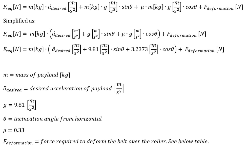
The deformation force you need to enter in the formula above (no load force) for each conveyor width is provided in the table below. This value represents the torque and equivalent force required to deform the belt over the conveyor rollers. The value also includes other small parasitic losses in the system.
Conveyor Belt Width (mm) | Deformation Force (N) |
|---|---|
305 | 44.5 |
610 | 89 |
914 | 112.7 |
1219 | 118.6 |
After obtaining the Required Driving Force from your calculation, compare it to the values in the table below.
Torque and Force
AC Motor + Gearbox Ratio | 0.5 HP AC Motor + 8:1 Gearbox | 0.5 HP AC Motor + 10:1 Gearbox | 0.5 HP AC Motor + 15:1 Gearbox |
|---|---|---|---|
Part Number | MO-SM-022-0005 | MO-SM-022-0007 | MO-SM-022-0009 |
Full - Load Torque Gearbox Output (N.m) | 16 | 20 | 30 |
Belt Conveyor Force (N) | 419 | 524 | 787 |
These forces are the maximum that the motor can deliver at its Full Load current. If the application requires more force (inclined conveyor orientation or higher acceleration) the conveyor speed might need to be reduced to achieve these values.
Transfer Plate
In some applications, you may need to line up several Dorner 3200 belt conveyors beside each other to move your products. In these cases, you need transfer plates to fill the gap between the conveyors. Transfer plates are installed at the ends of the conveyors. The transfer plate comes in four different dimensions to fit each of our conveyor widths offered (305mm, 610mm, 914mm and 1219mm). In order to use the transfer plate your product needs to have a minimum length of 32 mm. For Dorner 3200, the transfer plates for the drive tail of the conveyor (conveyor end with shaft) are different from the transfer plates for the idler tail of the conveyor (conveyor end without shaft).
AC Motor, Gearbox, and VFD
This kit is a lower-cost alternative to our stepper drives for powering your material-handling operations.
The VFD (variable frequency drive) powers a 1/2HP three-phase AC motor, which can be paired to a 8:1, 10:1 or 15:1 gearbox. It comes pre-wired for mains power, motor power, and three MachineMotion digital input connections. For more information can be found here: link.
Assembly Instructions
Assembly instructions can be found here. These instructions have been created to help you assemble the Dorner 3200 product with an AC motor and VFD configuration.