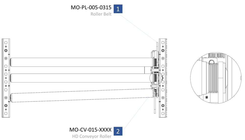
Overview
Vention’s HD conveyors are driven by three-rib v-belts, which can transmit over 200% more torque than a typical o-ring belt.
 Conveyor modularity, length and width |
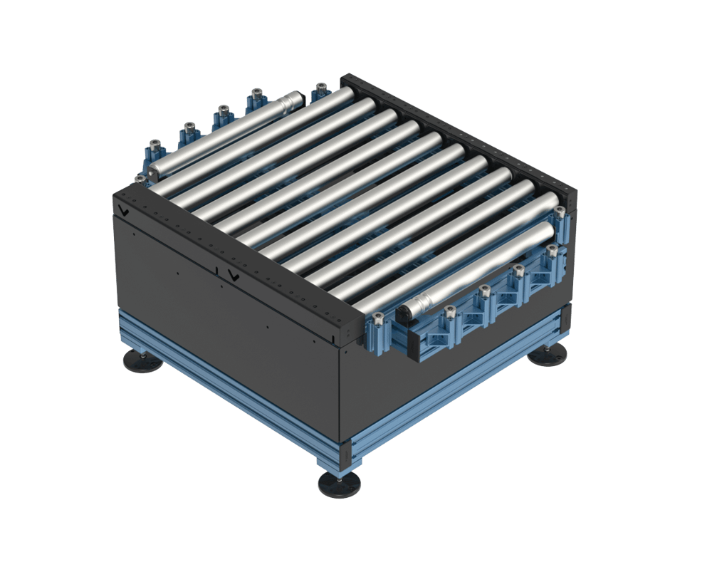
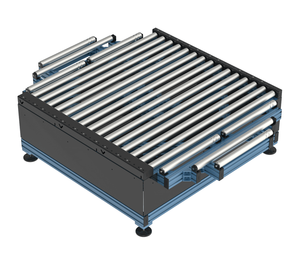
Perfect for transporting pallets and oversized items, the HD roller conveyor is available in widths of 855 mm and 1395 mm, and lengths that vary by 450 mm increments.
Applications
Pallet- and package-conveying are the two most popular applications. Sensors and logic can be easily added to automate the conveyor with MachineMotion, and allows you to take full advantage of Vention’s modular ecosystem to customize your conveyor.
Pallet Conveying
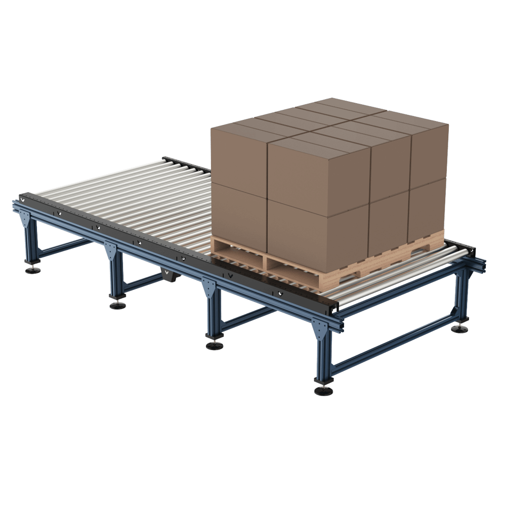 Pallet conveying application. |
With a maximum supported item width of 1344 mm (52.9 in.), the HD conveyor system can easily handle standard 48 inch-wide pallets. Note that for maximum load capacity, the pallet must be in contact with as many rollers as possible.
Pallet Conveyor Specifications | Roller width 675 mm | Roller width 855 mm | Roller width 1395 mm |
|---|---|---|---|
Suggested pallet width | 610 mm (24 in) | 765 mm (30 in) | 1215 mm (48 in) |
Pallet type | Wood or Plastic | Wood or Plastic | Wood or Plastic |
Max pallet weight (48 in length) | 440 kg | 440 kg | 440 kg |
Suggested motor size | 100 mm Nema 34 | 100 mm Nema 34 | 100 mm Nema 34 |
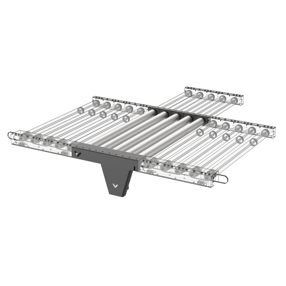
Determining the number of non- driven segments for pallets
To determine the number of motors for a run of conveyors, first determine the maximum permissible load for your pallet using the formula below. Notice that higher loads will reduce the conveyor speed.
|

The following table will help determine the number of non-driven segments between 2 driven segments. (see picture below)
Payload | Number of non-driven segments between 2 driven segments |
|---|---|
0 - 40 kg | 12 |
40 - 80 kg | 10 |
80 - 120 kg | 8 |
120 - 160 kg | 6 |
160 - 200 kg | 5 |
200 - 280 kg | 4 |
280 - 380 kg | 3 |
380 - 440 kg | 2 |
440 - 500 kg | 1 |
Important note: When you place the pallet on the conveyor, make sure the pallet bottom beams are perpendicular to the conveyor rollers not parallel, otherwise they may go into the empty space between the rollers, and the pallet will go slightly up, and down during the movement. (see the picture below)
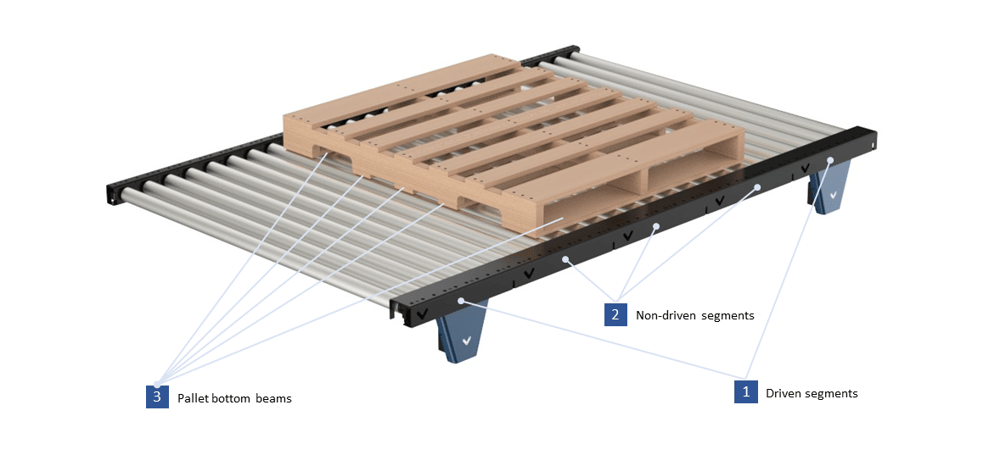 Driven and non-driven segments and pallet orientation on the conveyor |
Package Conveying
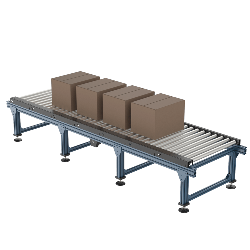 Packaging conveying application. |
The HD roller conveyor can also transport items or packages directly on the rollers, without the need for a pallet.
Before choosing which to use rollers to convey items directly, consider the following factors:
Rigidity. The conveyed items must be rigid. Flexible items will get caught between the rollers, which may cause the package to stall.
Bottom surface. Items must be flat on the bottom to maintain optimal contact with the rollers.
Length. Each item must be at least 180 mm long, in order to be in contact with at least two rollers at all times.
If your items don’t meet these conditions, you may want to consider our line of belt conveyors instead.
Package Conveyor Specifications | Roller width 675 mm | Roller width 855 mm | Roller width 1395 mm |
|---|---|---|---|
Max item width (25 mm clearance) | 600 mm | 780 mm | 1320 mm |
Item material | Stiff plastic and cardboard, wood, metal | Stiff plastic and cardboard, wood, metal | Stiff plastic and cardboard, wood, metal |
The maximum load you can have on the Vention HD roller conveyor for both pulling and pushing directions with a maximum of 5 segments after the driver segment is listed in the table below. The data applies to different speeds for both our ½ HP AC motor with a 3:1 gearbox (MO-SM-022-0000) and stepper motor (MO-SM-011-0000).
Load type | Direction | Maximum segments after | Speed (ft/min) | Speed (mm/s) | Maximum load (kg) |
|---|---|---|---|---|---|
Cardboard box* | Pulling / Pushing | 5 | 30 to 120 | 150 to 610 | 160 |
*Note: This is applicable to rigid materials such as cardboard boxes and is not valid for bagged goods. The load can be distributed or just one box.
Package Accumulation
In applications where you want to accumulate your product, several points need to be considered. The maximum accumulating load you can have on the Vention HD roller conveyor is 20 kg. This applies in both pushing and pulling directions with a maximum of 5 segments after the motorized segment (a total of 6 segments and 30 rollers). Performance was found to be similar with both our ½ HP AC motor with a 3:1 gearbox (MO-SM-022-0000) and stepper motor (MO-SM-011-0000). Also, you need to know that if you go higher than the maximum load, belts will slip and this leads to excessive belt wear. The table below summarizes the information.
Load type | Direction | Maximum segments after | Maximum accumulating load |
|---|---|---|---|
Cardboard box* | Pulling / Pushing | 5 | 20 (kg) |
*Note: This is applicable to rigid materials such as cardboard boxes and is not valid for bagged goods.
Package Picking
With the addition of the low side series, the HD conveyor can be used to deliver packages to a cartesian or robotic palletizer. The low side allows side box grippers and bag grippers fingers to fit between rollers, allowing larger boxes to be picked with ease. Assembly of this model is identical to the standard conveyor except the non-drive side is composed of the single low side bracket.
 Packaging picking application. |
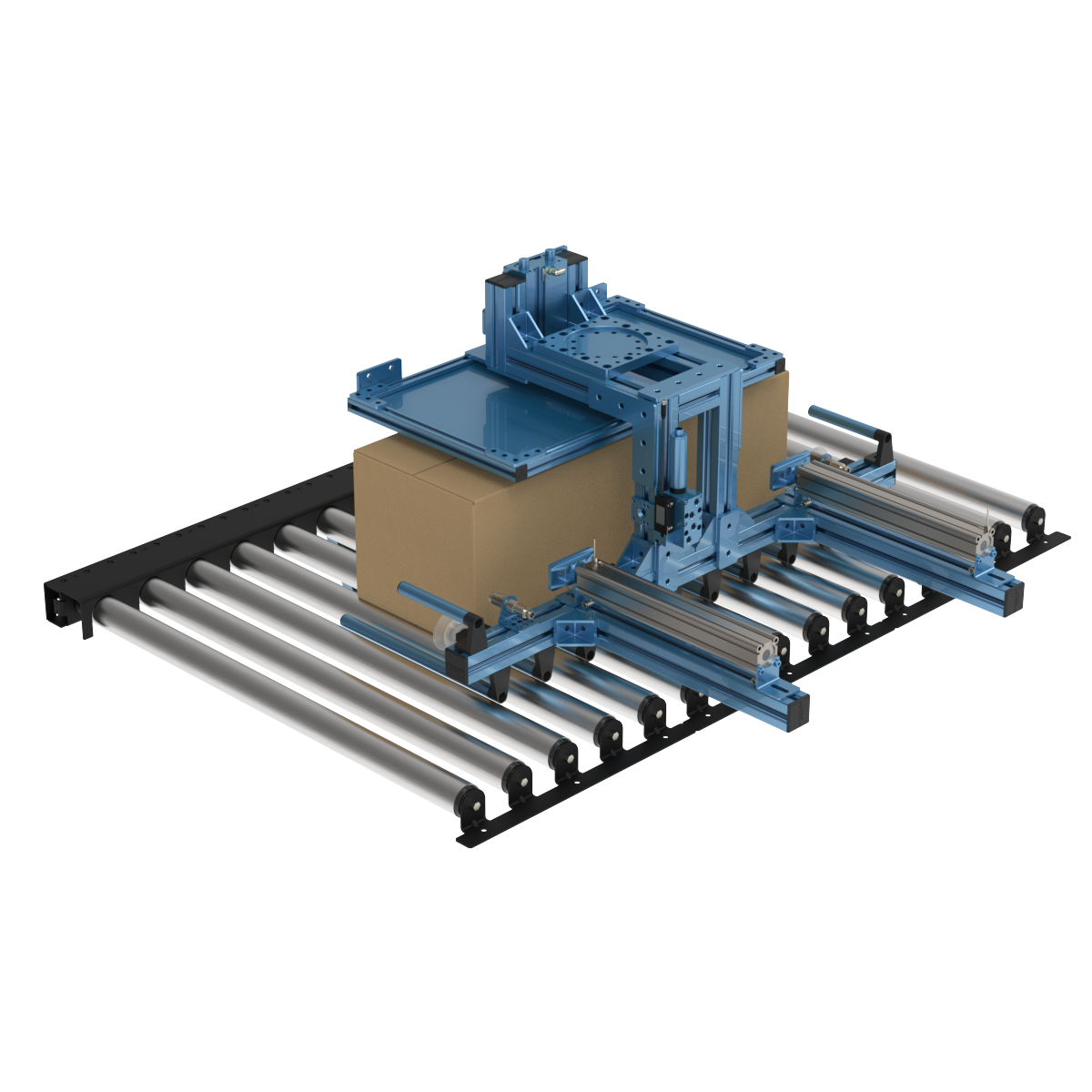
Conveyor Turntable
Conveyor turntables can be easily designed and modified to suit your needs. Turntables are used to change the direction of conveyed packages, merge two lines of conveyors or direct their flow. They are powered by servo motors, which offer the ability to position the turntable within nine arc minutes. Two pre-made designs are available, one for 855 mm width and one for 1395 mm width. Both can be easily modified to suit length requirements, sensor mounting or installed height.
Turntable Specs | Roller width 855 mm | Roller width 1395 mm |
|---|---|---|
Max Pallet Length | 900 mm | 1350 mm |
Turning Speed | 20 Degrees per second | 20 Degrees per second |
Capacity | 440 kg | 440 kg |
HD Conveyor Tech Specs
Nominal width | 675 mm | 855 mm | 1395mm |
|---|---|---|---|
Usable roller width | 624 mm | 804 mm | 1344 mm |
Length | 450 mm modular units | 450 mm modular units | 450 mm modular units |
Max capacity per roller | 40 kg (88 lb) | 40 kg (88 lb) | 40 kg (88 lb) |
Roller diameter | 50 mm | 50 mm | 50 mm |
Roller material | Zinc-plated steel | Zinc-plated steel | Zinc-plated steel |
Belt type | 4PJ | 4PJ | 4PJ |
Belt efficiency | 93% | 93% | 93% |
Max rollers per motor* | 30 | 30 | 30 |
Mechanical gain | 120.8 mm/revolution | 120.8 mm/revolution | 120.8 mm/revolution |
Driver Pulley PD | 35 mm | 35 mm | 35 mm |
Driven Pulley PD | 45.5 mm | 45.5 mm | 45.5 mm |
Max linear speed | 2000 mm/s | 2000 mm/s | 2000 mm/s |
*This is the maximum number of rollers that can be placed on either side of the motor for package conveying. For pallets check the table in the Pallet Conveying section.
Assembly Instructions
Before assembling the conveyor modules, ensure that the frame designed to hold them can bear the load of both the conveyor and the items being conveyed.
After the frame is built and leveled, you can proceed with assembling the conveyor segments.
Step 1: Install the mounting brackets
Attach each bracket with three M8 screws, using a 5 mm Allen key, and two cable mounts. Install the cable tie mounts to internally route cabling and tubing.
Repeat for each conveyor segment.
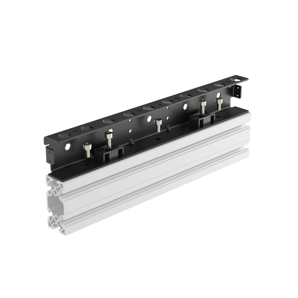 Conveyor bracket installation |
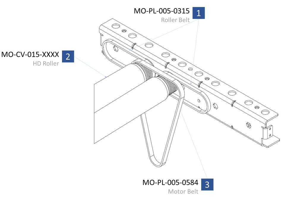
Step 2: Install the first two rollers
The easiest place to start installing rollers is with the first motor segment .
Starting at that segment, slip the belts onto the rollers, as shown.
Push the hex shaft into one side of the frame.
Depress the hex shaft and slide it into the second mounting bracket.
Repeat for the second roller.
Step 2: first roller installation.
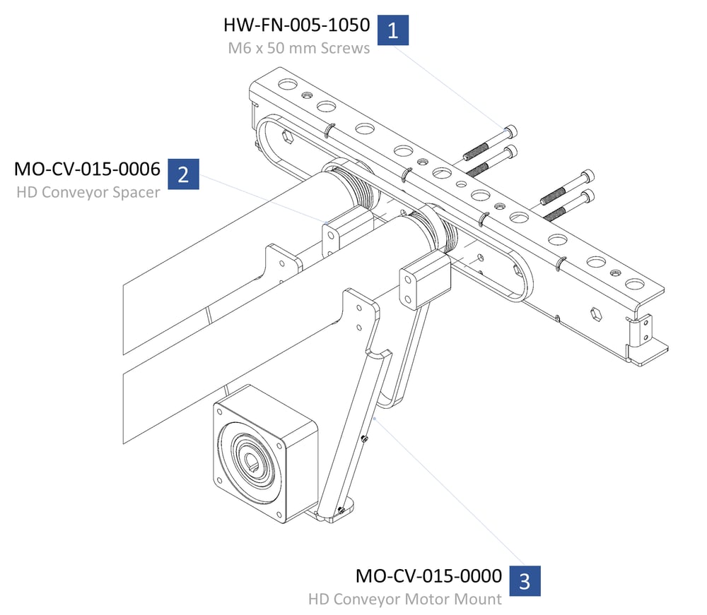
Step 3: Install the motor mount
Install the motor mount using four M6 screws and spacers, and tighten with a 5 mm Allen key.
Don’t worry about the exact placement of the belts, but make sure:
The belts are still in place.
The spacers go through the motor belt and one of the roller belts.
Step 3: motor mount installation.
Step 4: Install the drive belt
First, make sure the motor mount is at its highest position; this will help when installing the belt.
To move the mount up:
Loosen the four M6 bolts (1) and two M8 bolts on the bottom of the assembly. Once loose, the motor mount should slide up and down freely.
To install the drive belt:
Wrap the motor drive belt around the pulley. (It should sit flat once on the pulley.
Check the motor drive belt at each roller, and make sure it looks as shown in the figure below (2).
Step 4: drive belts installation.
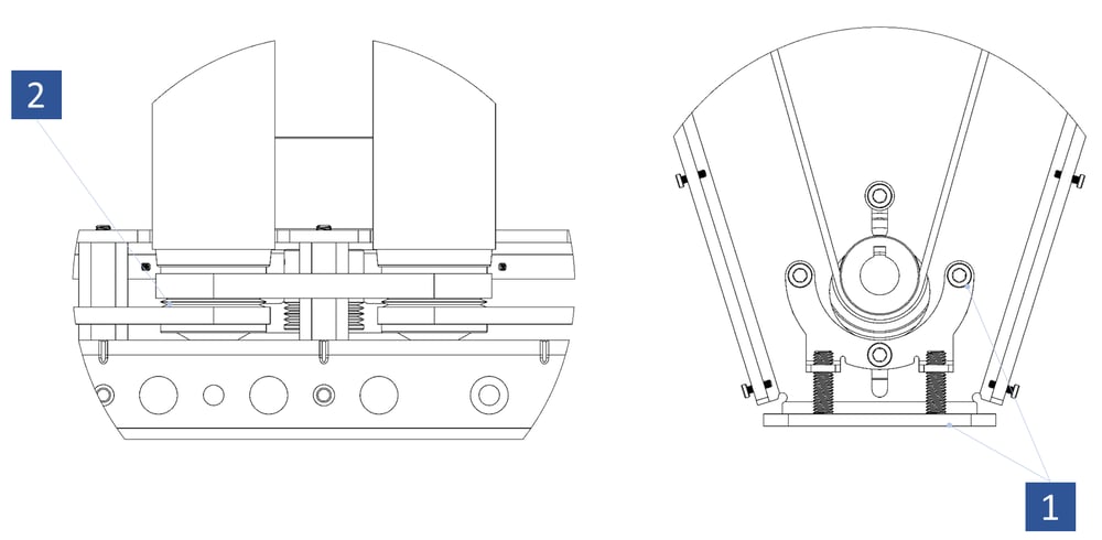
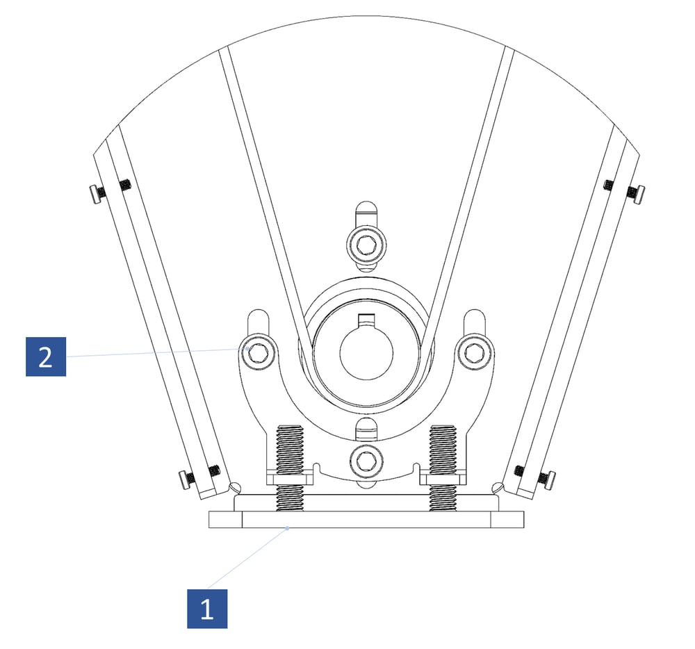
Step 5: Tension the drive belt
Start tightening the two M8 bolts found on the bottom of the assembly (1), but leave the four M6 screws loose (2).
Tighten the M8 bolts evenly by turning them two revolutions at a time. Keep tightening until proper tension is achieved.
To determine tension:
Remove the cover over the drive belt.
With a straight edge on the conveyor bracket, pull with a force gauge on the motor drive belt until the belt just barely touches the straight edge.
When the belt touches the straight edge, take the force reading.
Adjust the belt tension until the reading is between 90 N and 110 N.
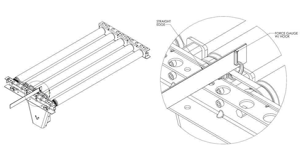
Step 5: Measuring the tension of the drive belt.
After proper tension is achieved, tighten the four M6 screws.
Note: If this step is performed after the installation of an AC Motor, please ensure that the motor support bolts attaching the motor to the extrusion frame are loose to allow for unimpeded tensioning adjustment.
 Step 5: drive belt tensioning. |
Step 6: Install the motor cover
Fasten the motor cover with four M3 screws and a 2 mm Allen key.
 Step 6: motor cover install. |
Step 7: Install additional rollers
To add the rest of the rollers:
First install the hex shaft on the non-driven side of the frame.
Add the two belts and depress the hex shaft.
Make sure the belt is in the right grooves on the roller. There should always be at least one groove between belts.
Slide the hex shaft into place on the frame.
The belt will be tight; it takes about 10 kg of force to move it into place. It’s easiest to pull the roller towards you.
 Step 7: additional roller installation. |
Step 8: Install the remaining rollers
If there are more powered sections, install the drive belt (as described in step 2). Install the second motor mount, refer to steps 3–6 for installation.
Otherwise, repeat step 7 for the remaining rollers and belts.
Step 9: Attach covers
Install the covers as shown. Attach each cover with four flathead M6 bolts, and tighten with a 4 mm Allen key. Repeat for each conveyor segment.
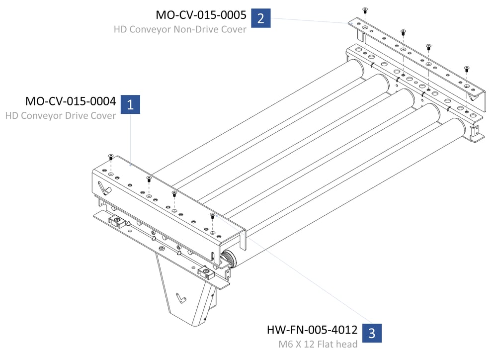 Step 9: attaching covers. |
Step 10: Attach end caps (optional)
If you have purchased end caps, attach one at each end. Fasten each end cap with two flathead M3 bolts, and tighten with a 2.5 mm Allen key.
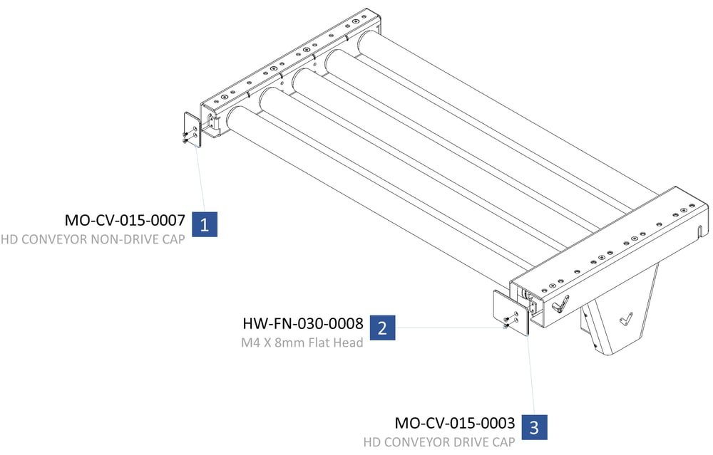 Step 10: attaching end caps. |
Maintenance
O-ring and v-belt rollers are low-maintenance, and all bearings are sealed and greased for life. All you need to do is routinely clean the rollers and check for wear.
Monthly
Clean rollers
Check for unusual noises
Check motor belt tension
Check roller belt tension
Check belt wear