EDS Download
Download MachineMotion EDS file →
Compatible with any PLC software including Rockwell Logix Designer/Studio 5000.
Introduction
EtherNet/IP is a widely used industrial communication protocol that allows for arbitrary devices to communicate over a standard ethernet link. With the MachineMotion EtherNet/IP adapter software, users are able to seamlessly integrate the MachineMotion and Vention ecosystem of motors, actuators, and IO modules with their existing industrial automation infrastructure.
In particular, MachineMotion EtherNet/IP was validated and thoroughly tested for easy and complete control of the MachineMotion hardware primitives from a Rockwell/Allen-Bradley PLC and for higher-level data exchange between custom MachineMotion applications and existing factory automation infrastructure.
This protocol offers two primary utilization options:
1) Users can maintain their existing control system as the parent and program the Vention system through it, utilizing the programming language of their current control system.
2) Users can establish process communication, including handshakes, with MachineMotion. This is particularly useful when integrating Vention equipment with non-Vention machines as part of a comprehensive solution.
Network Setup
Network Organization
After purchasing the EtherNet/IP package from Vention’s website and following the installation steps provided upon purchase, EtherNet/IP setup consists of properly configuring your ethernet network to allow devices to talk to one another. Practically, this means that the network should be configured so that all devices have unique IP addresses on a shared subnet.
For example, a standard network layout looks like the following diagram.
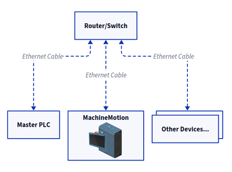 MachineMotion EtherNet/IP Network Layout Diagram |
MachineMotion IP Address Configuration
EtherNet/IP is supported via the LAN_1 configurable physical port on the front of the MachineMotion. To configure the network settings on this port see here.
Programming Basics
E-stop Feedback
To read the MachineMotion E-stop state, examine the E-stop tag in the input assembly. When the MachineMotion E-stop is triggered, the corresponding value will be 1 or true.
Digital Input Feedback
To read the pin states of any IO Modules installed with your MachineMotion, examine the corresponding IO Module X Input Pin Y tag values. To determine if the IO module is available on your MachineMotion, read the IO Module X Available tag.
Digital Output Control
To write pin states of any I/O modules installed with your MachineMotion, latch or unlatch the corresponding I/O Module X Output Pin Y tag values. To determine if the I/O module is available on your MachineMotion, read the I/O Module X Available tag.
Motion Control
MachineMotion supports three different move command types:
Absolute Moves in which the axis will move to a specified absolute position relative to the home position.
Relative Moves in which the axis will move an incremental distance from the current position.
Speed/Continuous Moves in which the axis will accelerate to a target speed and maintain until it is instructed to stop or accelerate to a different target speed.
Motion control via EtherNet/IP on the MachineMotion begins with the Drive X Enabled and Drive X Ready tags, which indicate if the Drive is enabled and ready to accept motion commands. To configure a move:
Set/Move a value into the Drive X Max Acceleration tag to the desired acceleration.
Set/Move a value into the Drive X Max Speed tag to the desired max speed.
Set/Move a value into the Drive X Target Position/Distance tag to set the desired position (Absolute Moves) or distance (Relative Moves). This property is not used for Speed/Continuous moves or for Homing.
Check that the drive is ready to move by reading the Drive X Ready tag. If the drive is not ready, this indicates that E-stop is triggered or one of the Drive X Start Relative/Absolute/Continuous Move tags is already latched high and needs to be brought low before another motion command is processed.
Latch the Drive X Start Relative/Absolute/Continuous Move bit HIGH to start the motion. When this is received by the controller, the Drive X Ready tag will drop low which indicates that the command has been received and the Drive X Start Relative/Absolute/Continuous Move bit can be unlatched LOW again.
Watch the Drive X Motion Complete go HIGH when the motion is complete and the target position has been reached.
A full listing of MachineMotion Input and Output Assembly tags and commands is found in the EDS file below.
EDS File
Device
NAME | VAL |
|---|---|
VendCode | 1761 |
VendName | Vention |
ProdType | 43 |
ProdTypeStr | Generic Device |
ProdCode | 65001 |
MajRev | 2 |
MinRev | 11 |
ProdName | MachineMotion |
Catalog | MachineMotion |
Assembly Objects
Assembly 100: Input Assembly (178 bytes)
NAME | DATA_TYPE | DATA_SIZE_BYTES | UNITS | HELP_STRING | OFFSET |
|---|---|---|---|---|---|
Drive 1 Current Position | REAL (Single precision floating point) | 4 | Millimeters | The current position of the drive (mm). Can be set to manually adjust the reference position. | 0 (0) |
Drive 1 Current Speed | REAL (Single precision floating point) | 4 | Millimeters per Second | The current speed of the drive (mm/s). | 4 (0) |
Drive 1 Current Torque | REAL (Single precision floating point) | 4 | Percentage of the rated torque | The current torque of the drive (%). | 8 (0) |
Drive 2 Current Position | REAL (Single precision floating point) | 4 | Millimeters | The current position of the drive (mm). Can be set to manually adjust the reference position. | 12 (0) |
Drive 2 Current Speed | REAL (Single precision floating point) | 4 | Millimeters per Second | The current speed of the drive (mm/s). | 16 (0) |
Drive 2 Current Torque | REAL (Single precision floating point) | 4 | Percentage of the rated torque | The current torque of the drive (%). | 20 (0) |
Drive 3 Current Position | REAL (Single precision floating point) | 4 | Millimeters | The current position of the drive (mm). Can be set to manually adjust the reference position. | 24 (0) |
Drive 3 Current Speed | REAL (Single precision floating point) | 4 | Millimeters per Second | The current speed of the drive (mm/s). | 28 (0) |
Drive 3 Current Torque | REAL (Single precision floating point) | 4 | Percentage of the rated torque | The current torque of the drive (%). | 32 (0) |
Drive 4 Current Position | REAL (Single precision floating point) | 4 | Millimeters | The current position of the drive (mm). Can be set to manually adjust the reference position. | 36 (0) |
Drive 4 Current Speed | REAL (Single precision floating point) | 4 | Millimeters per Second | The current speed of the drive (mm/s). | 40 (0) |
Drive 4 Current Torque | REAL (Single precision floating point) | 4 | Percentage of the rated torque | The current torque of the drive (%). | 44 (0) |
User Input Data 1 | DINT (32-bit signed integer) | 4 | User Defined Integer | Generic user data (received from MQTT: ethernet-ip/user-data/1/input). Use to pass information from your custom MachineLogic/python program to your PLC program. | 48 (0) |
User Input Data 2 | DINT (32-bit signed integer) | 4 | User Defined Integer | Generic user data (received from MQTT: ethernet-ip/user-data/2/input). Use to pass information from your custom MachineLogic/python program to your PLC program. | 52 (0) |
User Input Data 3 | DINT (32-bit signed integer) | 4 | User Defined Integer | Generic user data (received from MQTT: ethernet-ip/user-data/3/input). Use to pass information from your custom MachineLogic/python program to your PLC program. | 56 (0) |
User Input Data 4 | DINT (32-bit signed integer) | 4 | User Defined Integer | Generic user data (received from MQTT: ethernet-ip/user-data/4/input). Use to pass information from your custom MachineLogic/python program to your PLC program. | 60 (0) |
User Input Data 5 | DINT (32-bit signed integer) | 4 | User Defined Integer | Generic user data (received from MQTT: ethernet-ip/user-data/5/input). Use to pass information from your custom MachineLogic/python program to your PLC program. | 64 (0) |
User Input Data 6 | DINT (32-bit signed integer) | 4 | User Defined Integer | Generic user data (received from MQTT: ethernet-ip/user-data/6/input). Use to pass information from your custom MachineLogic/python program to your PLC program. | 68 (0) |
User Input Data 7 | DINT (32-bit signed integer) | 4 | User Defined Integer | Generic user data (received from MQTT: ethernet-ip/user-data/7/input). Use to pass information from your custom MachineLogic/python program to your PLC program. | 72 (0) |
User Input Data 8 | DINT (32-bit signed integer) | 4 | User Defined Integer | Generic user data (received from MQTT: ethernet-ip/user-data/8/input). Use to pass information from your custom MachineLogic/python program to your PLC program. | 76 (0) |
User Input Data 9 | DINT (32-bit signed integer) | 4 | User Defined Integer | Generic user data (received from MQTT: ethernet-ip/user-data/9/input). Use to pass information from your custom MachineLogic/python program to your PLC program. | 80 (0) |
User Input Data 10 | DINT (32-bit signed integer) | 4 | User Defined Integer | Generic user data (received from MQTT: ethernet-ip/user-data/10/input). Use to pass information from your custom MachineLogic/python program to your PLC program. | 84 (0) |
User Input Data 11 | DINT (32-bit signed integer) | 4 | User Defined Integer | Generic user data (received from MQTT: ethernet-ip/user-data/11/input). Use to pass information from your custom MachineLogic/python program to your PLC program. | 88 (0) |
User Input Data 12 | DINT (32-bit signed integer) | 4 | User Defined Integer | Generic user data (received from MQTT: ethernet-ip/user-data/12/input). Use to pass information from your custom MachineLogic/python program to your PLC program. | 92 (0) |
User Input Data 13 | DINT (32-bit signed integer) | 4 | User Defined Integer | Generic user data (received from MQTT: ethernet-ip/user-data/13/input). Use to pass information from your custom MachineLogic/python program to your PLC program. | 96 (0) |
User Input Data 14 | DINT (32-bit signed integer) | 4 | User Defined Integer | Generic user data (received from MQTT: ethernet-ip/user-data/14/input). Use to pass information from your custom MachineLogic/python program to your PLC program. | 100 (0) |
User Input Data 15 | DINT (32-bit signed integer) | 4 | User Defined Integer | Generic user data (received from MQTT: ethernet-ip/user-data/15/input). Use to pass information from your custom MachineLogic/python program to your PLC program. | 104 (0) |
User Input Data 16 | DINT (32-bit signed integer) | 4 | User Defined Integer | Generic user data (received from MQTT: ethernet-ip/user-data/16/input). Use to pass information from your custom MachineLogic/python program to your PLC program. | 108 (0) |
Status | BOOL | 1 | ONLINE/NONE | True if the MachineMotion is online. | 112 (0) |
Estop | BOOL | 1 | ESTOP/NONE | True if the MachineMotion is in Estop. | 113 (1) |
Drive 1 Enabled | BOOL | 1 | ENABLED/DISABLED | True if drive port is available on current hardware | 114 (2) |
Drive 1 Home Sensor Triggered | BOOL | 1 | TRIGGERED/OPEN | True if the home sensor is triggered. | 115 (3) |
Drive 1 End Sensor Triggered | BOOL | 1 | TRIGGERED/OPEN | True if the end sensor is triggered. | 116 (0) |
Drive 1 Motion Complete | BOOL | 1 | STOPPED/MOVING | True if motion is completed. | 117 (1) |
Drive 1 Brake Locked | BOOL | 1 | LOCKED/UNLOCKED | True if the brake is locked. Can be set to manually lock and unlock the brake. Should not be used to stop a moving axis. | 118 (2) |
Drive 1 Ready | BOOL | 1 | YES/NO | HIGH/YES if Drive 1 is ready to accept a trigger (Home, Quick Stop, Absolute, Relative or Continuous Move). When Drive 1 Ready goes LOW/NO, clear all Drive 1 triggers back to LOW. Drive 1 Ready is HIGH/YES when all Drive 1 triggers have been cleared on the MachineMotion, Drive 1 is enabled and Estop is LOW. | 119 (3) |
Drive 2 Enabled | BOOL | 1 | ENABLED/DISABLED | True if drive port is available on current hardware | 120 (0) |
Drive 2 Home Sensor Triggered | BOOL | 1 | TRIGGERED/OPEN | True if the home sensor is triggered. | 121 (1) |
Drive 2 End Sensor Triggered | BOOL | 1 | TRIGGERED/OPEN | True if the end sensor is triggered. | 122 (2) |
Drive 2 Motion Complete | BOOL | 1 | STOPPED/MOVING | True if motion is completed. | 123 (3) |
Drive 2 Brake Locked | BOOL | 1 | LOCKED/UNLOCKED | True if the brake is locked. Can be set to manually lock and unlock the brake. Should not be used to stop a moving axis. | 124 (0) |
Drive 2 Ready | BOOL | 1 | YES/NO | HIGH/YES if Drive 2 is ready to accept a trigger (Home, Quick Stop, Absolute, Relative or Continuous Move). When Drive 2 Ready goes LOW/NO, clear all Drive 2 triggers back to LOW. Drive 2 Ready is HIGH/YES when all Drive 2 triggers have been cleared on the MachineMotion, Drive 2 is enabled and Estop is LOW. | 125 (1) |
Drive 3 Enabled | BOOL | 1 | ENABLED/DISABLED | True if drive port is available on current hardware | 126 (2) |
Drive 3 Home Sensor Triggered | BOOL | 1 | TRIGGERED/OPEN | True if the home sensor is triggered. | 127 (3) |
Drive 3 End Sensor Triggered | BOOL | 1 | TRIGGERED/OPEN | True if the end sensor is triggered. | 128 (0) |
Drive 3 Motion Complete | BOOL | 1 | STOPPED/MOVING | True if motion is completed. | 129 (1) |
Drive 3 Brake Locked | BOOL | 1 | LOCKED/UNLOCKED | True if the brake is locked. Can be set to manually lock and unlock the brake. Should not be used to stop a moving axis. | 130 (2) |
Drive 3 Ready | BOOL | 1 | YES/NO | HIGH/YES if Drive 3 is ready to accept a trigger (Home, Quick Stop, Absolute, Relative or Continuous Move). When Drive 3 Ready goes LOW/NO, clear all Drive 3 triggers back to LOW. Drive 3 Ready is HIGH/YES when all Drive 3 triggers have been cleared on the MachineMotion, Drive 3 is enabled and Estop is LOW. | 131 (3) |
Drive 4 Enabled | BOOL | 1 | ENABLED/DISABLED | True if drive port is available on current hardware | 132 (0) |
Drive 4 Home Sensor Triggered | BOOL | 1 | TRIGGERED/OPEN | True if the home sensor is triggered. | 133 (1) |
Drive 4 End Sensor Triggered | BOOL | 1 | TRIGGERED/OPEN | True if the end sensor is triggered. | 134 (2) |
Drive 4 Motion Complete | BOOL | 1 | STOPPED/MOVING | True if motion is completed. | 135 (3) |
Drive 4 Brake Locked | BOOL | 1 | LOCKED/UNLOCKED | True if the brake is locked. Can be set to manually lock and unlock the brake. Should not be used to stop a moving axis. | 136 (0) |
Drive 4 Ready | BOOL | 1 | YES/NO | HIGH/YES if Drive 4 is ready to accept a trigger (Home, Quick Stop, Absolute, Relative or Continuous Move). When Drive 4 Ready goes LOW/NO, clear all Drive 4 triggers back to LOW. Drive 4 Ready is HIGH/YES when all Drive 4 triggers have been cleared on the MachineMotion, Drive 4 is enabled and Estop is LOW. | 137 (1) |
IO Module 1 Available | BOOL | 1 | YES/NO | True if the IO Module is available and connected to the MachineMotion. | 138 (2) |
IO Module 1 Input Pin 0 Value | BOOL | 1 | HIGH/LOW | The digital input pin value (HIGH/LOW). | 139 (3) |
IO Module 1 Input Pin 1 Value | BOOL | 1 | HIGH/LOW | The digital input pin value (HIGH/LOW). | 140 (0) |
IO Module 1 Input Pin 2 Value | BOOL | 1 | HIGH/LOW | The digital input pin value (HIGH/LOW). | 141 (1) |
IO Module 1 Input Pin 3 Value | BOOL | 1 | HIGH/LOW | The digital input pin value (HIGH/LOW). | 142 (2) |
IO Module 2 Available | BOOL | 1 | YES/NO | True if the IO Module is available and connected to the MachineMotion. | 143 (3) |
IO Module 2 Input Pin 0 Value | BOOL | 1 | HIGH/LOW | The digital input pin value (HIGH/LOW). | 144 (0) |
IO Module 2 Input Pin 1 Value | BOOL | 1 | HIGH/LOW | The digital input pin value (HIGH/LOW). | 145 (1) |
IO Module 2 Input Pin 2 Value | BOOL | 1 | HIGH/LOW | The digital input pin value (HIGH/LOW). | 146 (2) |
IO Module 2 Input Pin 3 Value | BOOL | 1 | HIGH/LOW | The digital input pin value (HIGH/LOW). | 147 (3) |
IO Module 3 Available | BOOL | 1 | YES/NO | True if the IO Module is available and connected to the MachineMotion. | 148 (0) |
IO Module 3 Input Pin 0 Value | BOOL | 1 | HIGH/LOW | The digital input pin value (HIGH/LOW). | 149 (1) |
IO Module 3 Input Pin 1 Value | BOOL | 1 | HIGH/LOW | The digital input pin value (HIGH/LOW). | 150 (2) |
IO Module 3 Input Pin 2 Value | BOOL | 1 | HIGH/LOW | The digital input pin value (HIGH/LOW). | 151 (3) |
IO Module 3 Input Pin 3 Value | BOOL | 1 | HIGH/LOW | The digital input pin value (HIGH/LOW). | 152 (0) |
IO Module 4 Available | BOOL | 1 | YES/NO | True if the IO Module is available and connected to the MachineMotion. | 153 (1) |
IO Module 4 Input Pin 0 Value | BOOL | 1 | HIGH/LOW | The digital input pin value (HIGH/LOW). | 154 (2) |
IO Module 4 Input Pin 1 Value | BOOL | 1 | HIGH/LOW | The digital input pin value (HIGH/LOW). | 155 (3) |
IO Module 4 Input Pin 2 Value | BOOL | 1 | HIGH/LOW | The digital input pin value (HIGH/LOW). | 156 (0) |
IO Module 4 Input Pin 3 Value | BOOL | 1 | HIGH/LOW | The digital input pin value (HIGH/LOW). | 157 (1) |
IO Module 5 Available | BOOL | 1 | YES/NO | True if the IO Module is available and connected to the MachineMotion. | 158 (2) |
IO Module 5 Input Pin 0 Value | BOOL | 1 | HIGH/LOW | The digital input pin value (HIGH/LOW). | 159 (3) |
IO Module 5 Input Pin 1 Value | BOOL | 1 | HIGH/LOW | The digital input pin value (HIGH/LOW). | 160 (0) |
IO Module 5 Input Pin 2 Value | BOOL | 1 | HIGH/LOW | The digital input pin value (HIGH/LOW). | 161 (1) |
IO Module 5 Input Pin 3 Value | BOOL | 1 | HIGH/LOW | The digital input pin value (HIGH/LOW). | 162 (2) |
IO Module 6 Available | BOOL | 1 | YES/NO | True if the IO Module is available and connected to the MachineMotion. | 163 (3) |
IO Module 6 Input Pin 0 Value | BOOL | 1 | HIGH/LOW | The digital input pin value (HIGH/LOW). | 164 (0) |
IO Module 6 Input Pin 1 Value | BOOL | 1 | HIGH/LOW | The digital input pin value (HIGH/LOW). | 165 (1) |
IO Module 6 Input Pin 2 Value | BOOL | 1 | HIGH/LOW | The digital input pin value (HIGH/LOW). | 166 (2) |
IO Module 6 Input Pin 3 Value | BOOL | 1 | HIGH/LOW | The digital input pin value (HIGH/LOW). | 167 (3) |
IO Module 7 Available | BOOL | 1 | YES/NO | True if the IO Module is available and connected to the MachineMotion. | 168 (0) |
IO Module 7 Input Pin 0 Value | BOOL | 1 | HIGH/LOW | The digital input pin value (HIGH/LOW). | 169 (1) |
IO Module 7 Input Pin 1 Value | BOOL | 1 | HIGH/LOW | The digital input pin value (HIGH/LOW). | 170 (2) |
IO Module 7 Input Pin 2 Value | BOOL | 1 | HIGH/LOW | The digital input pin value (HIGH/LOW). | 171 (3) |
IO Module 7 Input Pin 3 Value | BOOL | 1 | HIGH/LOW | The digital input pin value (HIGH/LOW). | 172 (0) |
IO Module 8 Available | BOOL | 1 | YES/NO | True if the IO Module is available and connected to the MachineMotion. | 173 (1) |
IO Module 8 Input Pin 0 Value | BOOL | 1 | HIGH/LOW | The digital input pin value (HIGH/LOW). | 174 (2) |
IO Module 8 Input Pin 1 Value | BOOL | 1 | HIGH/LOW | The digital input pin value (HIGH/LOW). | 175 (3) |
IO Module 8 Input Pin 2 Value | BOOL | 1 | HIGH/LOW | The digital input pin value (HIGH/LOW). | 176 (0) |
IO Module 8 Input Pin 3 Value | BOOL | 1 | HIGH/LOW | The digital input pin value (HIGH/LOW). | 177 (1) |
Assembly 150: Output Assembly (184 bytes)
NAME | DATA_TYPE | DATA_SIZE_BYTES | UNITS | HELP_STRING | OFFSET |
|---|---|---|---|---|---|
Set Drive 1 Current Position | REAL (Single precision floating point) | 4 | Millimeters | The current position of the drive (mm). Can be set to manually adjust the reference position. | 0 (0) |
Drive 1 Target Position/Distance | REAL (Single precision floating point) | 4 | Millimeters | The target position/distance (mm) for absolute/relative moves. | 4 (0) |
Drive 1 Max Speed | REAL (Single precision floating point) | 4 | Millimeters Per Second | The drive max speed (mm/s) for moves. | 8 (0) |
Drive 1 Max Acceleration | REAL (Single precision floating point) | 4 | Millimeters Per Second Squared | The drive max acceleration (mm/s^2) for moves. | 12 (0) |
Set Drive 2 Current Position | REAL (Single precision floating point) | 4 | Millimeters | The current position of the drive (mm). Can be set to manually adjust the reference position. | 16 (0) |
Drive 2 Target Position/Distance | REAL (Single precision floating point) | 4 | Millimeters | The target position/distance (mm) for absolute/relative moves. | 20 (0) |
Drive 2 Max Speed | REAL (Single precision floating point) | 4 | Millimeters Per Second | The drive max speed (mm/s) for moves. | 24 (0) |
Drive 2 Max Acceleration | REAL (Single precision floating point) | 4 | Millimeters Per Second Squared | The drive max acceleration (mm/s^2) for moves. | 28 (0) |
Set Drive 3 Current Position | REAL (Single precision floating point) | 4 | Millimeters | The current position of the drive (mm). Can be set to manually adjust the reference position. | 32 (0) |
Drive 3 Target Position/Distance | REAL (Single precision floating point) | 4 | Millimeters | The target position/distance (mm) for absolute/relative moves. | 36 (0) |
Drive 3 Max Speed | REAL (Single precision floating point) | 4 | Millimeters Per Second | The drive max speed (mm/s) for moves. | 40 (0) |
Drive 3 Max Acceleration | REAL (Single precision floating point) | 4 | Millimeters Per Second Squared | The drive max acceleration (mm/s^2) for moves. | 44 (0) |
Set Drive 4 Current Position | REAL (Single precision floating point) | 4 | Millimeters | The current position of the drive (mm). Can be set to manually adjust the reference position. | 48 (0) |
Drive 4 Target Position/Distance | REAL (Single precision floating point) | 4 | Millimeters | The target position/distance (mm) for absolute/relative moves. | 52 (0) |
Drive 4 Max Speed | REAL (Single precision floating point) | 4 | Millimeters Per Second | The drive max speed (mm/s) for moves. | 56 (0) |
Drive 4 Max Acceleration | REAL (Single precision floating point) | 4 | Millimeters Per Second Squared | The drive max acceleration (mm/s^2) for moves. | 60 (0) |
User Output Data 1 | DINT (32-bit signed integer) | 4 | User Defined Integer | Generic user data (published to MQTT: ethernet-ip/user-data/1/output). Use to pass information from your PLC program to your custom MachineLogic/python program. | 64 (0) |
User Output Data 2 | DINT (32-bit signed integer) | 4 | User Defined Integer | Generic user data (published to MQTT: ethernet-ip/user-data/2/output). Use to pass information from your PLC program to your custom MachineLogic/python program. | 68 (0) |
User Output Data 3 | DINT (32-bit signed integer) | 4 | User Defined Integer | Generic user data (published to MQTT: ethernet-ip/user-data/3/output). Use to pass information from your PLC program to your custom MachineLogic/python program. | 72 (0) |
User Output Data 4 | DINT (32-bit signed integer) | 4 | User Defined Integer | Generic user data (published to MQTT: ethernet-ip/user-data/4/output). Use to pass information from your PLC program to your custom MachineLogic/python program. | 76 (0) |
User Output Data 5 | DINT (32-bit signed integer) | 4 | User Defined Integer | Generic user data (published to MQTT: ethernet-ip/user-data/5/output). Use to pass information from your PLC program to your custom MachineLogic/python program. | 80 (0) |
User Output Data 6 | DINT (32-bit signed integer) | 4 | User Defined Integer | Generic user data (published to MQTT: ethernet-ip/user-data/6/output). Use to pass information from your PLC program to your custom MachineLogic/python program. | 84 (0) |
User Output Data 7 | DINT (32-bit signed integer) | 4 | User Defined Integer | Generic user data (published to MQTT: ethernet-ip/user-data/7/output). Use to pass information from your PLC program to your custom MachineLogic/python program. | 88 (0) |
User Output Data 8 | DINT (32-bit signed integer) | 4 | User Defined Integer | Generic user data (published to MQTT: ethernet-ip/user-data/8/output). Use to pass information from your PLC program to your custom MachineLogic/python program. | 92 (0) |
User Output Data 9 | DINT (32-bit signed integer) | 4 | User Defined Integer | Generic user data (published to MQTT: ethernet-ip/user-data/9/output). Use to pass information from your PLC program to your custom MachineLogic/python program. | 96 (0) |
User Output Data 10 | DINT (32-bit signed integer) | 4 | User Defined Integer | Generic user data (published to MQTT: ethernet-ip/user-data/10/output). Use to pass information from your PLC program to your custom MachineLogic/python program. | 100 (0) |
User Output Data 11 | DINT (32-bit signed integer) | 4 | User Defined Integer | Generic user data (published to MQTT: ethernet-ip/user-data/11/output). Use to pass information from your PLC program to your custom MachineLogic/python program. | 104 (0) |
User Output Data 12 | DINT (32-bit signed integer) | 4 | User Defined Integer | Generic user data (published to MQTT: ethernet-ip/user-data/12/output). Use to pass information from your PLC program to your custom MachineLogic/python program. | 108 (0) |
User Output Data 13 | DINT (32-bit signed integer) | 4 | User Defined Integer | Generic user data (published to MQTT: ethernet-ip/user-data/13/output). Use to pass information from your PLC program to your custom MachineLogic/python program. | 112 (0) |
User Output Data 14 | DINT (32-bit signed integer) | 4 | User Defined Integer | Generic user data (published to MQTT: ethernet-ip/user-data/14/output). Use to pass information from your PLC program to your custom MachineLogic/python program. | 116 (0) |
User Output Data 15 | DINT (32-bit signed integer) | 4 | User Defined Integer | Generic user data (published to MQTT: ethernet-ip/user-data/15/output). Use to pass information from your PLC program to your custom MachineLogic/python program. | 120 (0) |
User Output Data 16 | DINT (32-bit signed integer) | 4 | User Defined Integer | Generic user data (published to MQTT: ethernet-ip/user-data/16/output). Use to pass information from your PLC program to your custom MachineLogic/python program. | 124 (0) |
Set Drive 1 Brake Locked | BOOL | 1 | LOCKED/UNLOCKED | True if the brake is locked. Can be set to manually lock and unlock the brake. Should not be used to stop a moving axis. | 128 (0) |
Drive 1 Quick Stop | BOOL | 1 | HIGH/LOW | Trigger a Quick Stop on Drive 1 on rising edge/latch. Will be ignored if the Drive 1 Ready flag is LOW. Unlatch/set to LOW after Drive 1 Ready flag goes LOW/NO. | 129 (1) |
Drive 1 Start Home | BOOL | 1 | HIGH/LOW | Trigger a Start Home on Drive 1 on rising edge/latch. Will be ignored if the Drive 1 Ready flag is LOW. Unlatch/set to LOW after Drive 1 Ready flag goes LOW/NO. | 130 (2) |
Drive 1 Start Absolute Move | BOOL | 1 | HIGH/LOW | Trigger a Start Absolute Move on Drive 1 on rising edge/latch. Will be ignored if the Drive 1 Ready flag is LOW. Unlatch/set to LOW after Drive 1 Ready flag goes LOW/NO. | 131 (3) |
Drive 1 Start Relative Move | BOOL | 1 | HIGH/LOW | Trigger a Start Relative Move on Drive 1 on rising edge/latch. Will be ignored if the Drive 1 Ready flag is LOW. Unlatch/set to LOW after Drive 1 Ready flag goes LOW/NO. | 132 (0) |
Drive 1 Start Continuous Move | BOOL | 1 | HIGH/LOW | Trigger a Start Continuous Move on Drive 1 on rising edge/latch. Will be ignored if the Drive 1 Ready flag is LOW. Unlatch/set to LOW after Drive 1 Ready flag goes LOW/NO. | 133 (1) |
Set Drive 2 Brake Locked | BOOL | 1 | LOCKED/UNLOCKED | True if the brake is locked. Can be set to manually lock and unlock the brake. Should not be used to stop a moving axis. | 134 (2) |
Drive 2 Quick Stop | BOOL | 1 | HIGH/LOW | Trigger a Quick Stop on Drive 2 on rising edge/latch. Will be ignored if the Drive 2 Ready flag is LOW. Unlatch/set to LOW after Drive 2 Ready flag goes LOW/NO. | 135 (3) |
Drive 2 Start Home | BOOL | 1 | HIGH/LOW | Trigger a Start Home on Drive 2 on rising edge/latch. Will be ignored if the Drive 2 Ready flag is LOW. Unlatch/set to LOW after Drive 2 Ready flag goes LOW/NO. | 136 (0) |
Drive 2 Start Absolute Move | BOOL | 1 | HIGH/LOW | Trigger a Start Absolute Move on Drive 2 on rising edge/latch. Will be ignored if the Drive 2 Ready flag is LOW. Unlatch/set to LOW after Drive 2 Ready flag goes LOW/NO. | 137 (1) |
Drive 2 Start Relative Move | BOOL | 1 | HIGH/LOW | Trigger a Start Relative Move on Drive 2 on rising edge/latch. Will be ignored if the Drive 2 Ready flag is LOW. Unlatch/set to LOW after Drive 2 Ready flag goes LOW/NO. | 138 (2) |
Drive 2 Start Continuous Move | BOOL | 1 | HIGH/LOW | Trigger a Start Continuous Move on Drive 2 on rising edge/latch. Will be ignored if the Drive 2 Ready flag is LOW. Unlatch/set to LOW after Drive 2 Ready flag goes LOW/NO. | 139 (3) |
Set Drive 3 Brake Locked | BOOL | 1 | LOCKED/UNLOCKED | True if the brake is locked. Can be set to manually lock and unlock the brake. Should not be used to stop a moving axis. | 140 (0) |
Drive 3 Quick Stop | BOOL | 1 | HIGH/LOW | Trigger a Quick Stop on Drive 3 on rising edge/latch. Will be ignored if the Drive 3 Ready flag is LOW. Unlatch/set to LOW after Drive 3 Ready flag goes LOW/NO. | 141 (1) |
Drive 3 Start Home | BOOL | 1 | HIGH/LOW | Trigger a Start Home on Drive 3 on rising edge/latch. Will be ignored if the Drive 3 Ready flag is LOW. Unlatch/set to LOW after Drive 3 Ready flag goes LOW/NO. | 142 (2) |
Drive 3 Start Absolute Move | BOOL | 1 | HIGH/LOW | Trigger a Start Absolute Move on Drive 3 on rising edge/latch. Will be ignored if the Drive 3 Ready flag is LOW. Unlatch/set to LOW after Drive 3 Ready flag goes LOW/NO. | 143 (3) |
Drive 3 Start Relative Move | BOOL | 1 | HIGH/LOW | Trigger a Start Relative Move on Drive 3 on rising edge/latch. Will be ignored if the Drive 3 Ready flag is LOW. Unlatch/set to LOW after Drive 3 Ready flag goes LOW/NO. | 144 (0) |
Drive 3 Start Continuous Move | BOOL | 1 | HIGH/LOW | Trigger a Start Continuous Move on Drive 3 on rising edge/latch. Will be ignored if the Drive 3 Ready flag is LOW. Unlatch/set to LOW after Drive 3 Ready flag goes LOW/NO. | 145 (1) |
Set Drive 4 Brake Locked | BOOL | 1 | LOCKED/UNLOCKED | True if the brake is locked. Can be set to manually lock and unlock the brake. Should not be used to stop a moving axis. | 146 (2) |
Drive 4 Quick Stop | BOOL | 1 | HIGH/LOW | Trigger a Quick Stop on Drive 4 on rising edge/latch. Will be ignored if the Drive 4 Ready flag is LOW. Unlatch/set to LOW after Drive 4 Ready flag goes LOW/NO. | 147 (3) |
Drive 4 Start Home | BOOL | 1 | HIGH/LOW | Trigger a Start Home on Drive 4 on rising edge/latch. Will be ignored if the Drive 4 Ready flag is LOW. Unlatch/set to LOW after Drive 4 Ready flag goes LOW/NO. | 148 (0) |
Drive 4 Start Absolute Move | BOOL | 1 | HIGH/LOW | Trigger a Start Absolute Move on Drive 4 on rising edge/latch. Will be ignored if the Drive 4 Ready flag is LOW. Unlatch/set to LOW after Drive 4 Ready flag goes LOW/NO. | 149 (1) |
Drive 4 Start Relative Move | BOOL | 1 | HIGH/LOW | Trigger a Start Relative Move on Drive 4 on rising edge/latch. Will be ignored if the Drive 4 Ready flag is LOW. Unlatch/set to LOW after Drive 4 Ready flag goes LOW/NO. | 150 (2) |
Drive 4 Start Continuous Move | BOOL | 1 | HIGH/LOW | Trigger a Start Continuous Move on Drive 4 on rising edge/latch. Will be ignored if the Drive 4 Ready flag is LOW. Unlatch/set to LOW after Drive 4 Ready flag goes LOW/NO. | 151 (3) |
IO Module 1 Output Pin 0 Value | BOOL | 1 | HIGH/LOW | Set to toggle the digital output pin state (HIGH/LOW). | 152 (0) |
IO Module 1 Output Pin 1 Value | BOOL | 1 | HIGH/LOW | Set to toggle the digital output pin state (HIGH/LOW). | 153 (1) |
IO Module 1 Output Pin 2 Value | BOOL | 1 | HIGH/LOW | Set to toggle the digital output pin state (HIGH/LOW). | 154 (2) |
IO Module 1 Output Pin 3 Value | BOOL | 1 | HIGH/LOW | Set to toggle the digital output pin state (HIGH/LOW). | 155 (3) |
IO Module 2 Output Pin 0 Value | BOOL | 1 | HIGH/LOW | Set to toggle the digital output pin state (HIGH/LOW). | 156 (0) |
IO Module 2 Output Pin 1 Value | BOOL | 1 | HIGH/LOW | Set to toggle the digital output pin state (HIGH/LOW). | 157 (1) |
IO Module 2 Output Pin 2 Value | BOOL | 1 | HIGH/LOW | Set to toggle the digital output pin state (HIGH/LOW). | 158 (2) |
IO Module 2 Output Pin 3 Value | BOOL | 1 | HIGH/LOW | Set to toggle the digital output pin state (HIGH/LOW). | 159 (3) |
IO Module 3 Output Pin 0 Value | BOOL | 1 | HIGH/LOW | Set to toggle the digital output pin state (HIGH/LOW). | 160 (0) |
IO Module 3 Output Pin 1 Value | BOOL | 1 | HIGH/LOW | Set to toggle the digital output pin state (HIGH/LOW). | 161 (1) |
IO Module 3 Output Pin 2 Value | BOOL | 1 | HIGH/LOW | Set to toggle the digital output pin state (HIGH/LOW). | 162 (2) |
IO Module 3 Output Pin 3 Value | BOOL | 1 | HIGH/LOW | Set to toggle the digital output pin state (HIGH/LOW). | 163 (3) |
IO Module 4 Output Pin 0 Value | BOOL | 1 | HIGH/LOW | Set to toggle the digital output pin state (HIGH/LOW). | 164 (0) |
IO Module 4 Output Pin 1 Value | BOOL | 1 | HIGH/LOW | Set to toggle the digital output pin state (HIGH/LOW). | 165 (1) |
IO Module 4 Output Pin 2 Value | BOOL | 1 | HIGH/LOW | Set to toggle the digital output pin state (HIGH/LOW). | 166 (2) |
IO Module 4 Output Pin 3 Value | BOOL | 1 | HIGH/LOW | Set to toggle the digital output pin state (HIGH/LOW). | 167 (3) |
IO Module 5 Output Pin 0 Value | BOOL | 1 | HIGH/LOW | Set to toggle the digital output pin state (HIGH/LOW). | 168 (0) |
IO Module 5 Output Pin 1 Value | BOOL | 1 | HIGH/LOW | Set to toggle the digital output pin state (HIGH/LOW). | 169 (1) |
IO Module 5 Output Pin 2 Value | BOOL | 1 | HIGH/LOW | Set to toggle the digital output pin state (HIGH/LOW). | 170 (2) |
IO Module 5 Output Pin 3 Value | BOOL | 1 | HIGH/LOW | Set to toggle the digital output pin state (HIGH/LOW). | 171 (3) |
IO Module 6 Output Pin 0 Value | BOOL | 1 | HIGH/LOW | Set to toggle the digital output pin state (HIGH/LOW). | 172 (0) |
IO Module 6 Output Pin 1 Value | BOOL | 1 | HIGH/LOW | Set to toggle the digital output pin state (HIGH/LOW). | 173 (1) |
IO Module 6 Output Pin 2 Value | BOOL | 1 | HIGH/LOW | Set to toggle the digital output pin state (HIGH/LOW). | 174 (2) |
IO Module 6 Output Pin 3 Value | BOOL | 1 | HIGH/LOW | Set to toggle the digital output pin state (HIGH/LOW). | 175 (3) |
IO Module 7 Output Pin 0 Value | BOOL | 1 | HIGH/LOW | Set to toggle the digital output pin state (HIGH/LOW). | 176 (0) |
IO Module 7 Output Pin 1 Value | BOOL | 1 | HIGH/LOW | Set to toggle the digital output pin state (HIGH/LOW). | 177 (1) |
IO Module 7 Output Pin 2 Value | BOOL | 1 | HIGH/LOW | Set to toggle the digital output pin state (HIGH/LOW). | 178 (2) |
IO Module 7 Output Pin 3 Value | BOOL | 1 | HIGH/LOW | Set to toggle the digital output pin state (HIGH/LOW). | 179 (3) |
IO Module 8 Output Pin 0 Value | BOOL | 1 | HIGH/LOW | Set to toggle the digital output pin state (HIGH/LOW). | 180 (0) |
IO Module 8 Output Pin 1 Value | BOOL | 1 | HIGH/LOW | Set to toggle the digital output pin state (HIGH/LOW). | 181 (1) |
IO Module 8 Output Pin 2 Value | BOOL | 1 | HIGH/LOW | Set to toggle the digital output pin state (HIGH/LOW). | 182 (2) |
IO Module 8 Output Pin 3 Value | BOOL | 1 | HIGH/LOW | Set to toggle the digital output pin state (HIGH/LOW). | 183 (3) |
Assembly 151: Config Assembly (0 bytes)
Empty
Example of configuration steps to interface MachineMotion to a PLC through EtherNet/IP provided below.
Studio 5000 Setup Guide
The most common use case of EtherNet/IP is to enable the MachineMotion to be programmed from a Rockwell/Allen-Bradley PLC. The steps to import the MachineMotion EDS file and create a new MachineMotion module are detailed below.
EDS Installation and MachineMotion Module Creation
After saving the MachineMotion EDS file available at the top of this page to your computer and opening up your Studio 5000 project, the first step to install the MachineMotion EDS is to navigate to the “Tools” menu and click on the “EDS Hardware Installation Tool.”
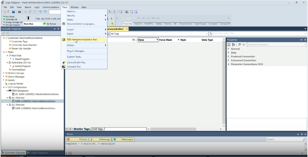
Studio 5000 Tool Menu
This will open Rockwell Automation’s Device Wizard. Click “Next” and choose “Register a device description file(s).”
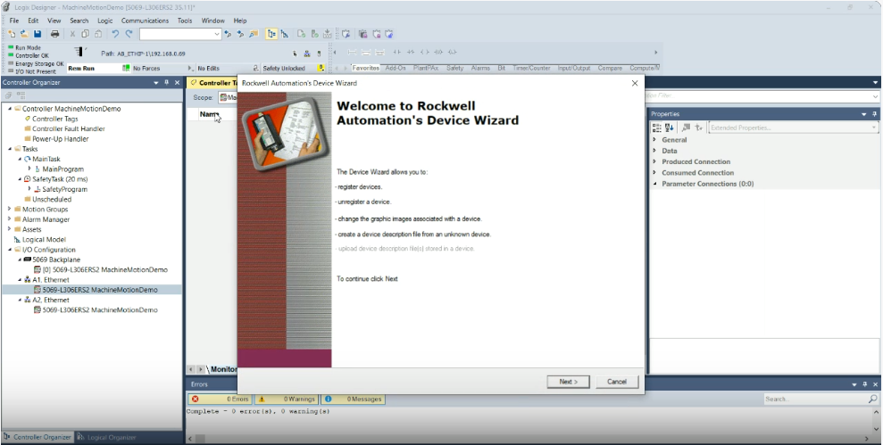
EDS Hardware Installation Tool Welcome
Select the MachineMotion EDS file you have saved to your computer and click “Next” through the subsequent menu screens.
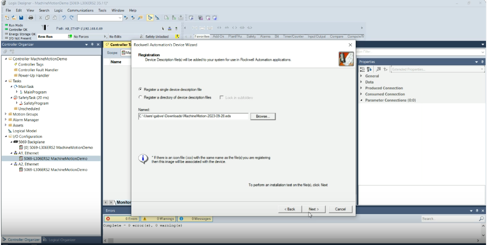
Studio 5000 Register MachineMotion EDS
Once you have reached the end, click “Finish.” The MachineMotion EDS is now installed in your project.
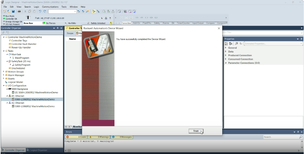
Studio 5000 Hardware Installation Machine Motion Finish
Now it’s time to create a MachineMotion Module. To install the MachineMotion Module and connect to the MachineMotion, use the Controller Organizer menu and expand the I/O Configuration tree. Right-click on the Ethernet interface corresponding to the location of the MachineMotion/PLC network and select “New Module…” in the dropdown.
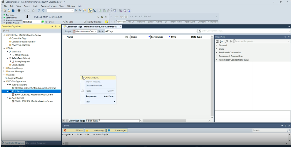
Studio 5000 New Module MachineMotion
Inside the Select Module Type menu, search for MachineMotion, click on the MachineMotion device, and select “Create.”
Studio 5000 Create New MachineMotion Module
This will open the New Module properties menu. Provide a name for this MachineMotion module and enter the MachineMotion IP address that you have configured in MachineMotion ControlCenter.
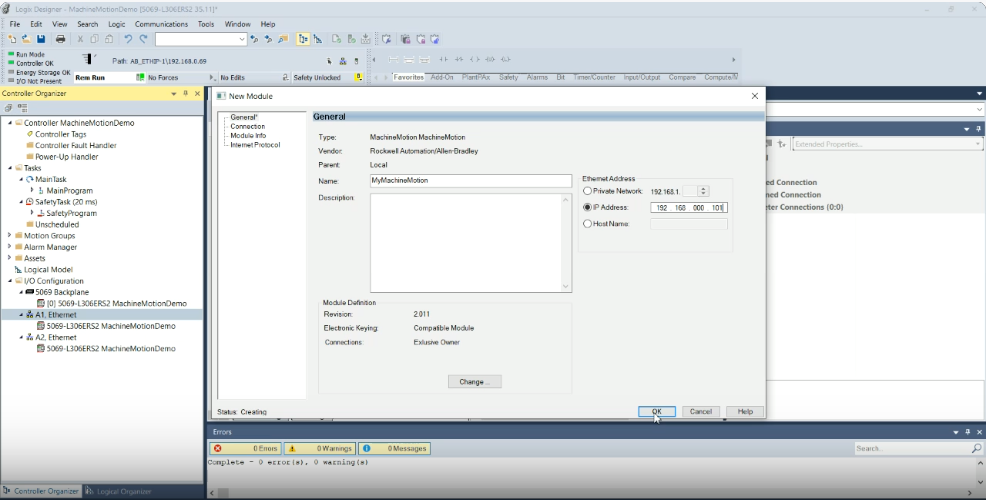
Studio 5000 MachineMotion IP Address
Select “OK.” The MachineMotion module should now appear in your I/O Configuration tree and the labeled MachineMotion tags should be visible inside of the Controller Tags view. To test the connection, take the controller online and validate that the I/O OK indicator in the top-left is solid green.
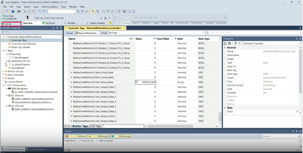
Studio 5000 IO OK MachineMotion
Video Guide to Installing MachineMotion EDS File and Connecting to Logic’s Designer
In this instructional video, we will guide you through the process of installing a MachineMotion EDS file and connecting it to the MachineMotion controller within Logic’s Designer. This tutorial covers everything from initiating the EDS hardware installation tool to testing communication, ensuring a thorough and precise configuration.
You are now ready to commence programming in your Studio5000 environment. For detailed instructions on programming your machine, kindly consult the external documentation supplied by the manufacturers.