Introduction
MachineMotion v2 datasheet contains detailed technical specifications, such as: functional pinout, input & outputs, specifications, input / output capabilities by model, electronics & embedded software specifications and unit dimensions.
Overview
MachineMotion v2 is a plug and play industrial controller that contains the necessary infrastructure to execute motion and control applications through a library of modular components. Equipment powered by MachineMotion v2 can be programmed through MachineLogic – Vention’s code-free visual sequence editor – or through Vention’s Python SDK.
MachineMotion 1 datasheet can be found in the ‘Documentation for Previous Product Versions’ at the bottom of this page
Features
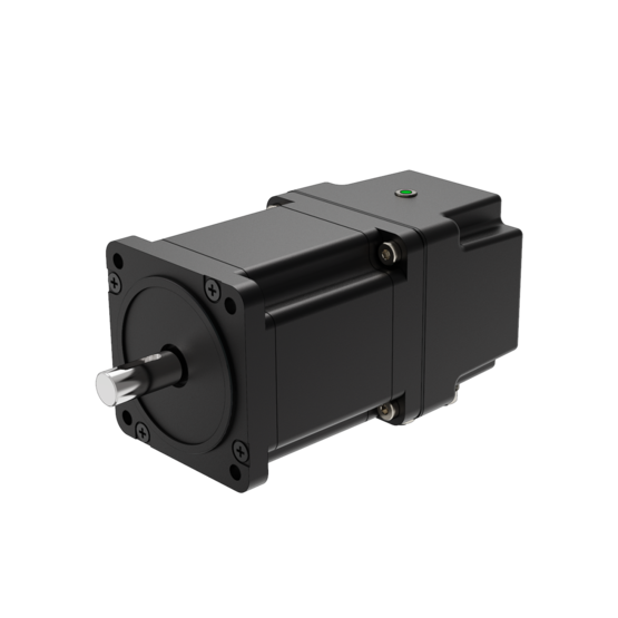
Control up to four 250 W high performance step-servos with accurate and automatic position adjustments. This allows the actuator to always reach the user-specified position, thanks to a built-in encoder that enables the motors to operate in closed control loops.
Step-servo junction box with simple cabling, where the brake, home and end-stop sensors can be directly wired to the motor.
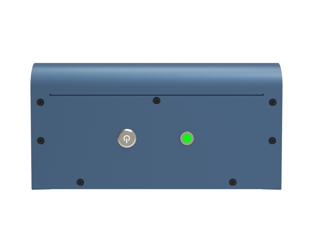
Status light on servo motors and controller for quick diagnostics
Loaded with code-free software including:
Control Center
MachineLogic
Python
Open source development tools including:
Cloud 9 IDE
Javascript
Operator mode
Manual joggers
The MachineMotion v2 controller is certified to Canadian, US & European standards.
IP30 rated enclosure for industrial applications, with active cooling and replaceable filters
Connect digital I/O and analog modules to control I/O devices
Supports multiple external communication protocols including MQTT & EtherNet/IP
Single continuous flex cable to power an actuator, sensors and power-off brake
Plug and play with all Vention actuators
Native support for Universal Robots with URcap
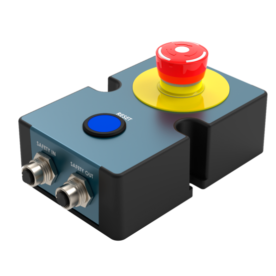
Plug and play safety system with physical and software reset
Directly connect peripherals locally or remotely using the teach pendant, keyboard, mouse, and monitor
Applications
Automated equipment
Cartesian robot
Functional and reliability test benches
Conveyor system
Inspection cells
Supported robot interfaces
Fanuc
Universal robots
ABB
Doosan
Electrical Specifications
Certifications | |
North America |
|
Europe |
|
Power Port | |
Name | POWER |
Rated Voltage | 85 to 264 VAC |
Rated Current | 9A @ 120 VAC |
Typical Current | 4.5A @ 120 VAC |
Typical Power | 1200 W |
Standby Current | 0.7 A (@ power factor 0.55) |
Standby Power | 84 W |
Emergency Mode Current | 0.4 A (@ power factor 0.3) |
Emergency Mode Power | 48 W |
Connector | IEC C14 |
Power Cord | 3.00m, NEMA 5-15P to IEC 320-C13, SJT |
Drive Ports | |
Name(s) | DRIVE 1, DRIVE 2, DRIVE 3, DRIVE 4 |
Motor Type | Servo-Stepper |
Output Peak Voltage | 50 V |
Maximum Output Current | 10 A |
Maximum Output Power | 350 W |
Phase Current Peak | 0 - 10 A |
Phase Current Adjustment (Internal) | Software controlled |
Control Interface (Internal) | CAN/(Step-Dir-Enable) Signals |
Motor Drivers Certification | CE |
Connector | M23 Amphenol Sine |
Pin 1 | 24 V |
Pin 2 | 0 V |
Pin 3 | motor phase A+ |
Pin 4 | motor phase A- |
Pin 5 | motor phase B+ |
Pin 6 | motor phase B- |
Pin 7 | Encoder A+ |
Pin 8 | Encoder A- |
Pin 9 | Encoder B+ |
Pin 10 | Encoder B- |
Pin 11 | Encoder Index+ |
Pin 12 | Encoder Index- |
Pin 13 | NC |
Pin 14 | NC |
Pin 15 | Home/End Limit Switch S1 |
Pin 16 | Home/End Limit Switch S2 |
Pin 17 | 24V Safety Switched |
Control (1,2,3,4) Ports | |
Name(s) | Control 1, Control 2, Control 3, Control 4 |
Connectivity Type | Communication |
Connectivity Physical Layer | CAN/RS485 |
Connector | M12, female, 8-pin, A-Keyed |
Pin 1 | 24 V (70W max) |
Pin 2 | 0 V |
Pin 3 | RS485 A |
Pin 4 | RS485 B |
Pin 5 | CAN H |
Pin 6 | CAN L |
Pin 7 | NC |
Pin 8 | 24V Safety Switched |
To PC Port | |
Name(s) | To PC |
Connectivity Type | Ethernet |
Connectivity Physical Layer | IEEE 802.3, Ethernet |
Connector | RJ45 |
LAN Ports | |
Name(s) | LAN 1, LAN 2 |
Connectivity Type | Ethernet |
Connectivity Physical Layer | IEEE 802.3, Ethernet |
Connector | RJ45 |
USB Ports | |
Name(s) | USB 1, USB 2 |
Connectivity Type | USB |
Connectivity Physical Layer | USB 2.0 |
Connector | USB-A 2.0 |
HDMI Ports | |
Name(s) | HDMI |
Connectivity Type | HDMI |
Connectivity Physical Layer | HDMI |
Connector | HDMI Type A |
Note: drives inside the MachineMotion 2 operate at 48VDC and are designed to power 2-phase stepper motors. They can deliver up to 10A of current per phase. The maximum power consumption for all the drives together is 1000W. | |
Name(s) | SAFETY IN / PENDANT |
Type | Redundant Dry Contacts + Reset |
Connectivity Physical Layer | IEEE 802.3, Ethernet |
Connector | M12, female, 12-pin, A-Keyed |
Pin 1 | 24 V (70W max) |
Pin 2 | 0 V |
Pin 3 | E-Stop IN Channel 1 Contact 1 |
Pin 4 | E-Stop IN Channel 1 Contact 2 |
Pin 5 | E-Stop IN Channel 2 Contact 1 |
Pin 6 | E-Stop IN Channel 2 Contact 2 |
Pin 7 | Reset Contact 1 |
Pin 8 | Reset Contact 2 |
Pin 9 | Ethernet TX+ |
Pin 10 | Ethernet TX- |
Pin 11 | Ethernet RX+ |
Pin 12 | Ethernet RX- |
Safety Out Port | |
Name(s) | SAFETY OUT |
Type | Redundant Dry Contacts + Reset |
Connector | M12, female, 12-pin, A-Keyed |
Pin 1 | NC |
Pin 2 | 0 V |
Pin 3 | E-Stop OUT Channel 1 Contact 1 |
Pin 4 | E-Stop OUT Channel 1 Contact 2 |
Pin 5 | E-Stop OUT Channel 2 Contact 1 |
Pin 6 | E-Stop OUT Channel 2 Contact 2 |
Pin 7 | Reset Contact 1 |
Pin 8 | Reset Contact 2 |
Pin 9 | NC |
Pin 10 | NC |
Pin 11 | NC |
Pin 12 | NC |
Ethernet Port | |
Name(s) | ETHERNET |
Connectivity Type | Standard Ethernet |
Physical Layer | IEEE 802.3, Ethernet |
Connector | RJ45, 8p8c |
Pin 1 | NC |
Pin 2 | TX+ |
Pin 3 | TX- |
Pin 4 | RX+ |
Pin 5 | RX- |
Pin 6 | NC |
Pin 7 | NC |
Pin 8 | NC |
Default Ethernet or 192.168.7.2 Port | |
Name | DEFAULT ETHERNET or 192.168.7.2 |
Status | Unused |
Embedded & Computing Specifications
Single Board Computer | |
Processor | TI AM5729 |
OS | Debian 10 |
Memory | 32GB SD-micro |
Certification | CE |
Motion Controller | |
Processor | Natotec CL4 |
Interface | CAN |
Protocol | G-code |
Fieldbus Compatible Modules | |
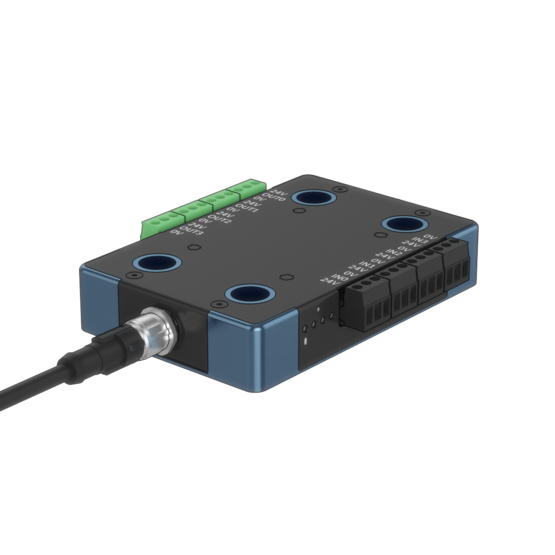
Digital IO Module | CE-MD-001-0001 |
Analog IO Module | CE-MD-003-0000 *available soon |
Push-Button Module | CE-MD-004-0000 |
Safety Specifications
Safety PLC | |
Manufacturer | ReeR |
Model Number | M1 |
Safety Data - Values per EN ISO 13849-1 | |
Category | 3 |
Performance Level | PLe |
MTTFd | 64 years |
DCavg | 97.3 % |
PFHD | 8.84E-08 h<>-1 |
Safety Data - Values per IEC/EN 61508 | |
SIL | 2 (IEC/EN 61508) |
HFT (hardware failure tolerance) | 1 |
DCavg | 97.3% |
SFF | 99.70% |
PFHD | 1.45E-08 h<>-1 |
Operation conditions | |
dop | 365 days/year |
hop | 24 hours/day |
Tcycle | 8640 s/cycle |
Vention ControlCenter Software
MachineMotion comes with pre-loaded control and machine operations software – all of which is accessible through the MachineMotion pendant or via computer with a USB or Ethernet connection.
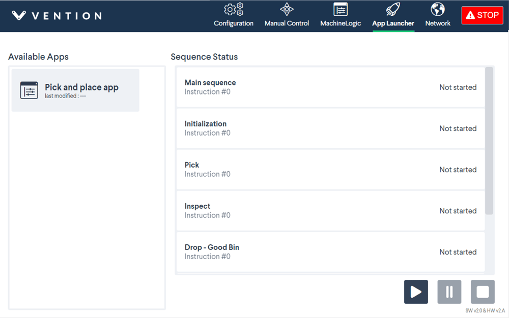
Application Launcher
Launch MachineLogic Applications
Launch Python Applications
Configure programs in auto-launch mode (executes automatically after power-ON)
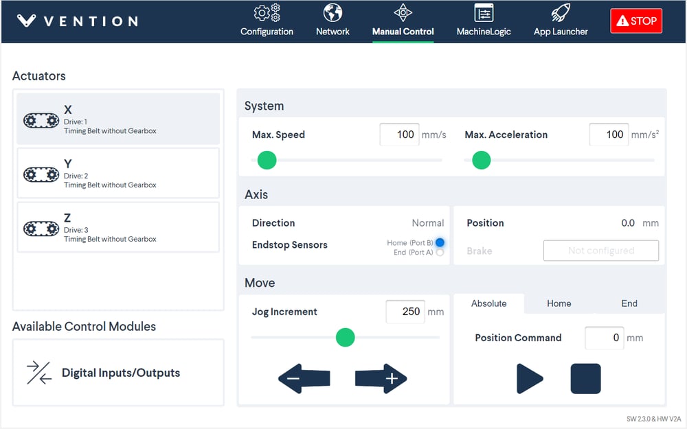
Manual Control
Send motion commands to actuators
Configure speed, acceleration and direction
Monitor the state of end-of-travel sensors and connected control devices
MachineLogic
Create automation programs in a simple graphical interface

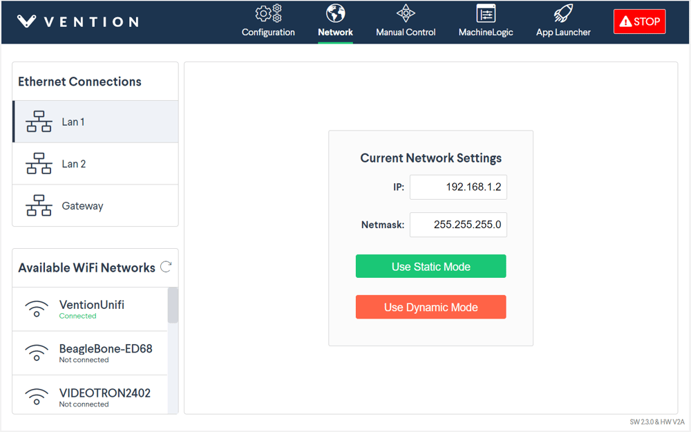
Network Configuration
Configure the Ethernet ports and WiFi settings (only if the MachineMotion controller is connected to a MachineMotion pendant)
Software & Communication Protocol Specifications
Available Control API |
Python |
Communication Protocol for Ethernet Adapter |
web-socket |
Communication Protocol for Fieldbus |
MQTT |
Security |
MachineCloud connection is encrypted (TLS 1.2 & TLS 1.3, A-rated ciphers, RSA 2048-bit keypairs on server and client) |
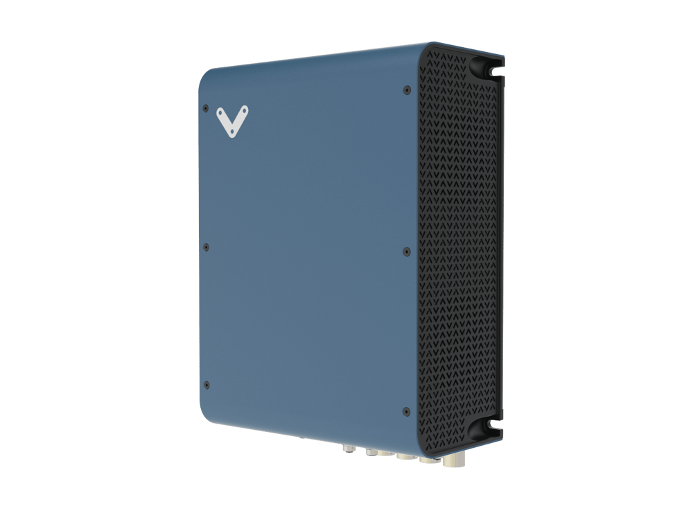
Physical Unit
|
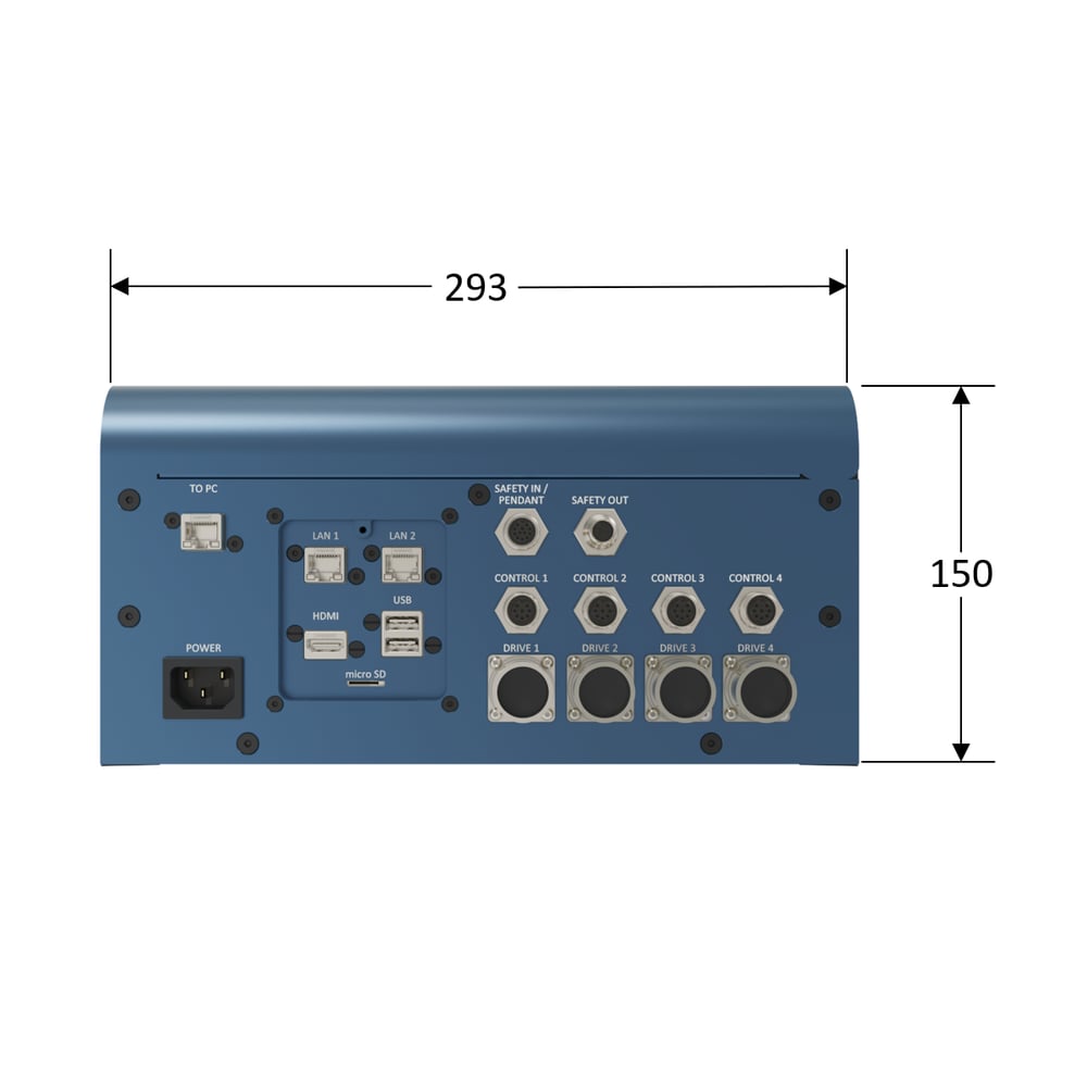
Functional Pinout
|
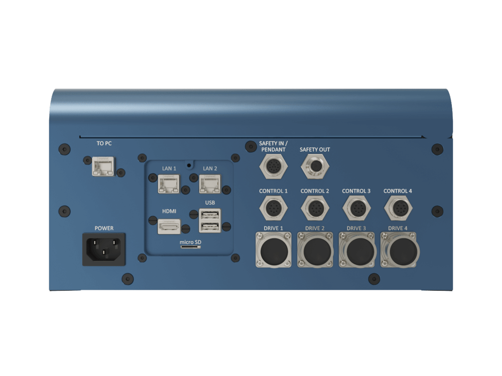
|
Unit Dimensions
|
|
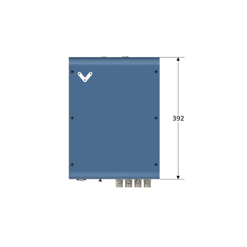
NOTE: In order to provide proper air flow to the MachineMotion controller, a minimum clearance of 150mm is required between the MachineMotion controller and any structure. If 2 or more MachineMotion controllers are used in a design a minumum of 300mm of clearance is required between them.
Compatible Hardware
Plug and Play Automation Components
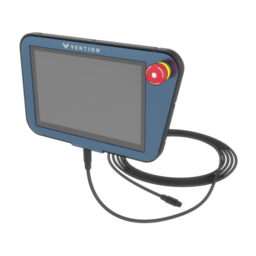
MachineMotionTM Pendant
|
CE-SN-004-0001
|
CE-MD-001-0001
|
MO-PT-002-0001
|
MO-SM-01X-0000
|
CE-SA-007-0000
|
.png)
.png)