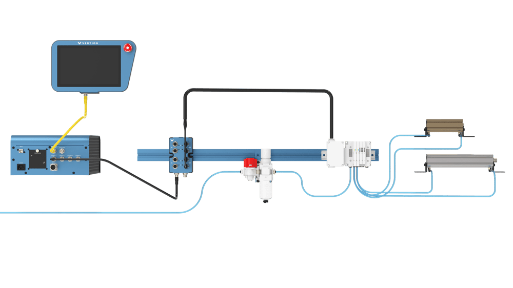
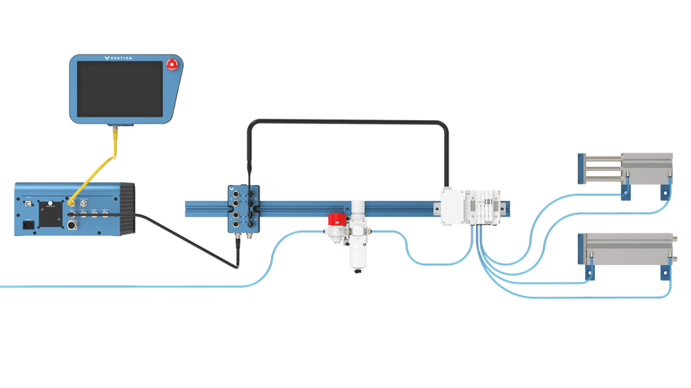
Overview
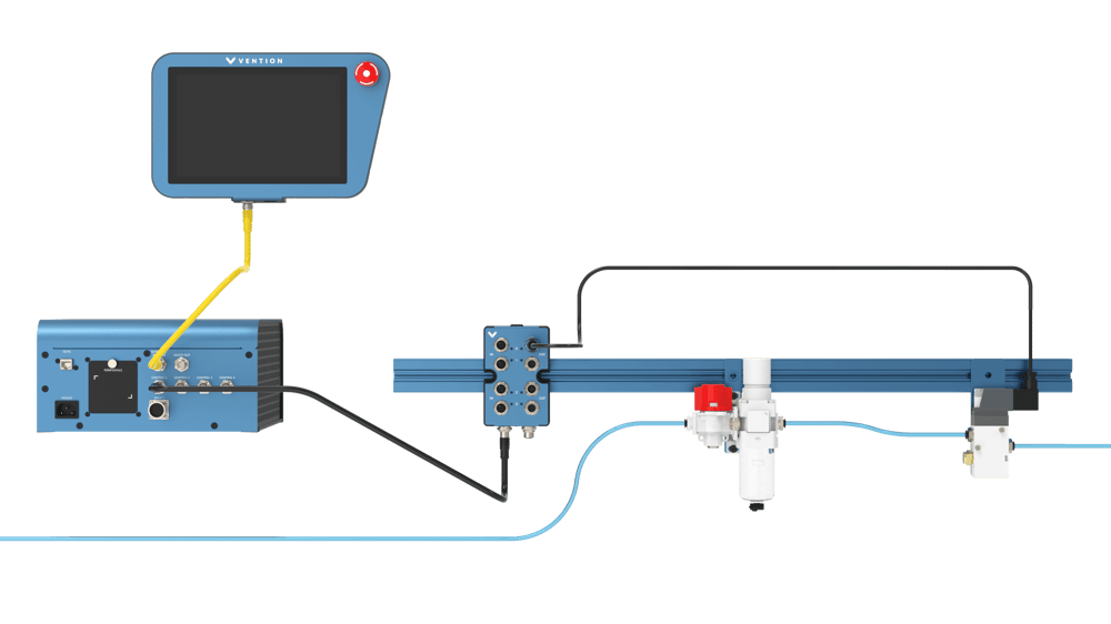
Vention has partnered with SMC, an industry leader in pneumatics, to bring you a series of pneumatic components. These components include an air preparation station complete with a pressure regulator, air filter and manual safety release valve, a manifold that supports up to four independent open-center valves that drive various lengths of double-acting cylinders. The entire system is controlled using Vention’s MachineMotion 2 (CE-CL-010-0004) and Digital I/O Module v2 (CE-MD-001-0000__2).
This user manual provides technical specifications for Vention’s Pneumatic Ecosystem V2. For details on Vention’s Penumatic Ecosystem V1, refer to the ‘Documentation for Previous Product Versions’ section at the end of this document.
Applications
There are several applications for the pneumatic ecosystem, including clamping and guidance systems.
Air Preparation Station (CA-AP-001-0001/0002)
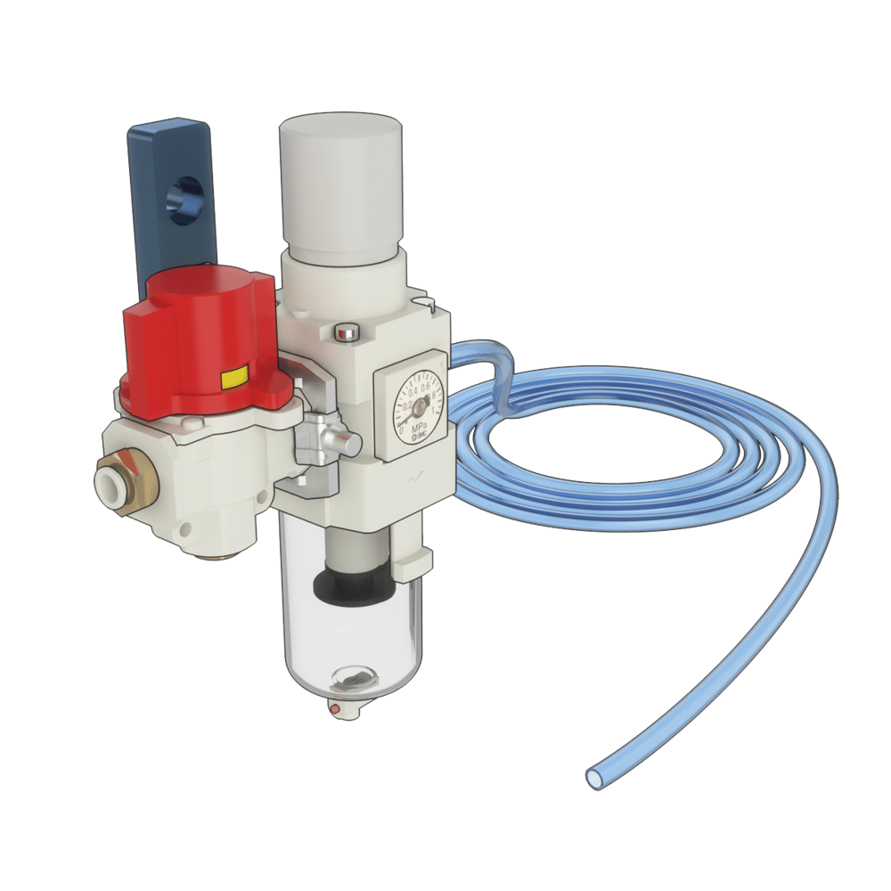 Air Preparation Station |
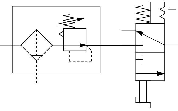 Symbol |
Specifications
Flow Coefficient Cv | 2.3 |
Operating Temperature [°C] | -5 to 60 |
Maximum Operating Pressure [MPa] | 1.0 |
Filter Drain Capacity [ml] | 25 |
Filter Filtration Rating [μm] | 5 |
Included Tubing | 12mm OD Polyurethane Tubing - 5 meters in length |
Pneumatic Pressure Regulator (CA-AP-002-0001/0005)
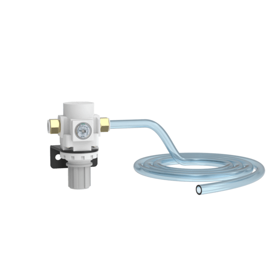 Pressure Regulator | 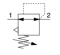 Symbol |
Specifications
Flow Coefficient Cv | 2.3 |
Operating Temperature [°C] | -5 to 60 |
Maximum Operating Pressure [MPa] | 1.0 |
Set Pressure Range [MPa] | 0.05 to 0.85 |
Included Tubing | 12mm OD Polyurethane Tubing - 3 meters in length |
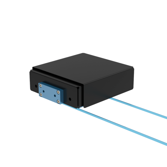
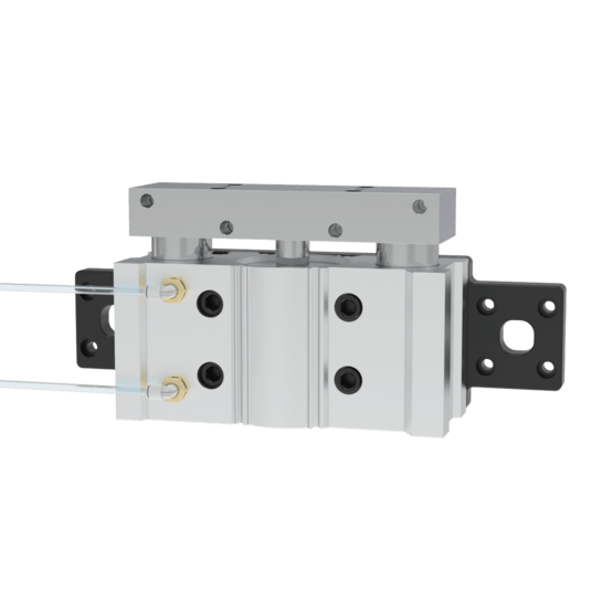
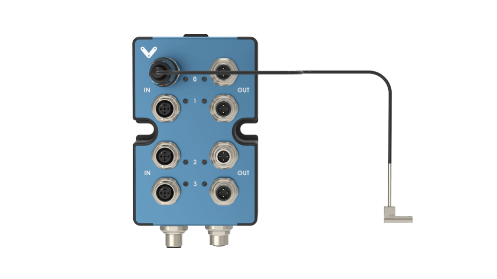
Manifold Station with Valves (CA-CO-001-0002/0004)
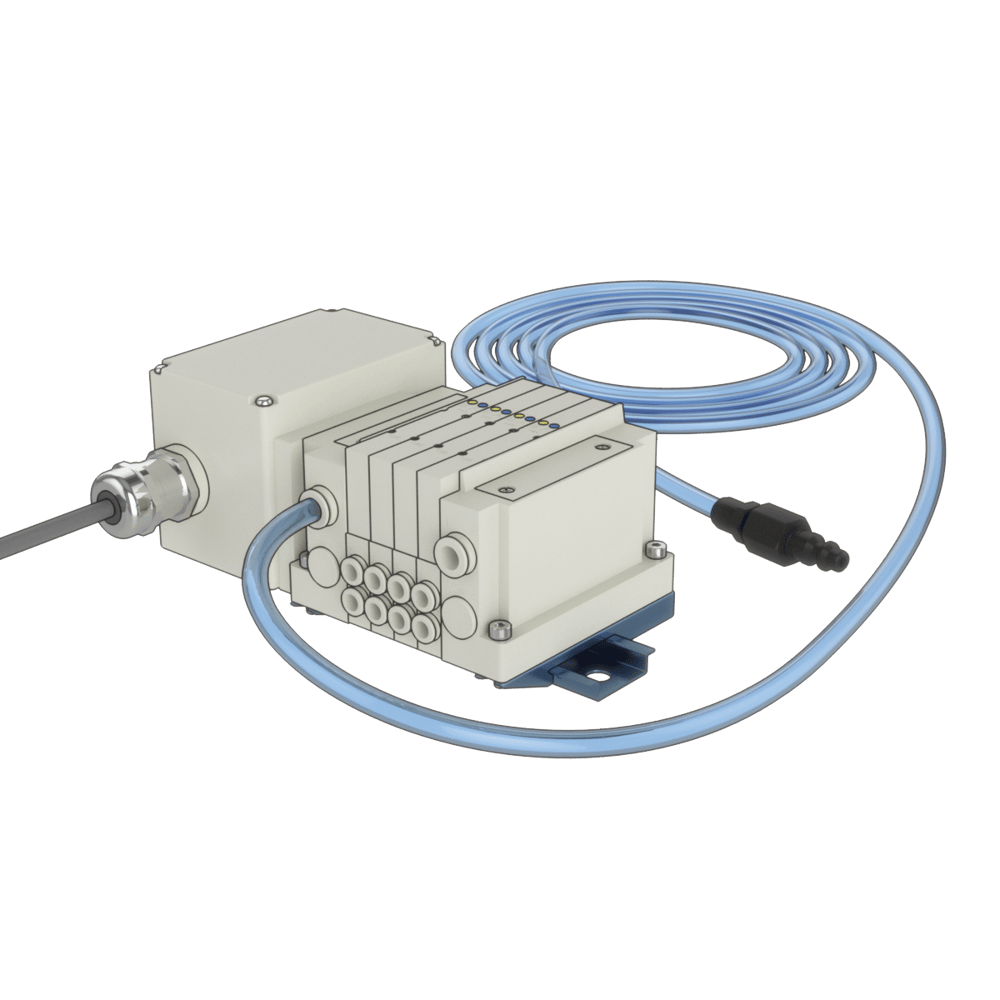 Manifold Station with Valves | 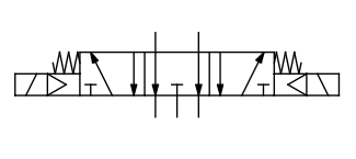 Valve Symbol |
Specifications
Available Valve Stations | 2 and 4 |
Flow Coefficient Cv per valve | 0.3 |
Operating Temperature [°C] | -10 to 50 |
Maximum Operating Pressure [MPa] | 0.7 |
Minimum Operating Pressure [MPa] | 0.2 |
Control Voltage [V] | 24 |
Maximum Power Consumption [W] | 0.35 |
Enclosure Rating | IP67 |
Included Tubing | 12mm OD Polyurethane Tubing - 3 meters in length with industrial |
Wiring
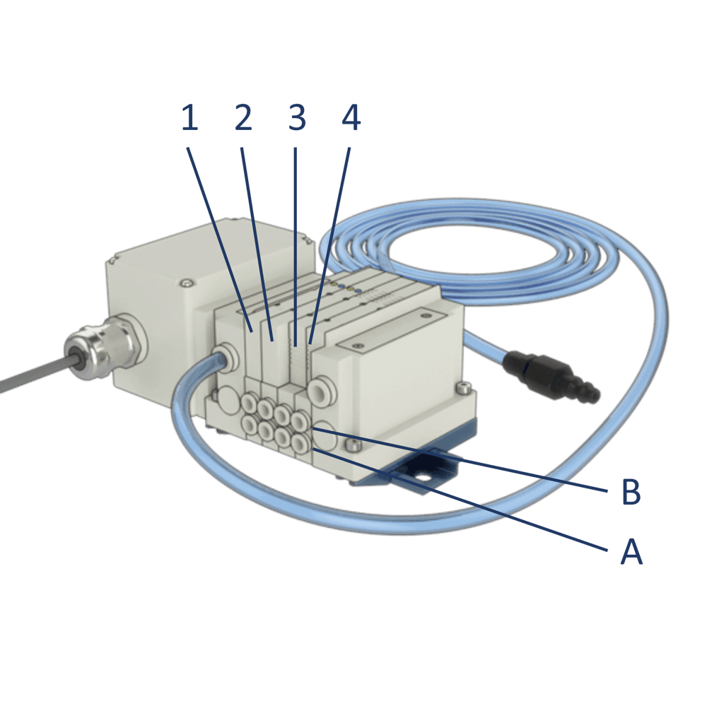
Every Manifold Station comes pre-wired with M12 4-pin female connectors. Each M12 connector allows the control of a single valve output, with each valve having 2 outputs (A and B). Since a Digital I/O Module v2 (CE-MD-001-0000__2) has 4 outputs ports, up to 2 valves can be controlled by a single module. Simply connect every M12 connector to a digital output port (follow the labeling) and start controlling the manifold out-of-the-box.
Valve and output numbering goes as follows on the manifold station:
|
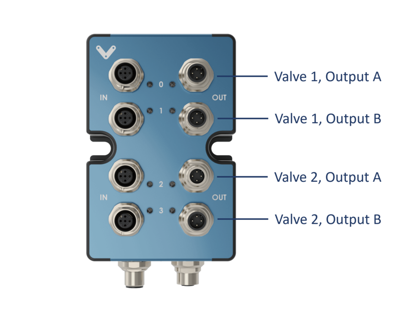
A 2-Valve Manifold Station (CA-CO-001-0002__2) cable has 4 labeled M12 connectors that control valve outputs as follows:
|
A 4-Valve Manifold Station (CA-CO-001-0004__2) cable has 8 labeled M12 connectors that control valve outputs as follows:
|
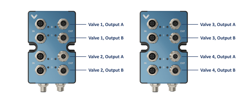
Each valve has a LED indicator reflecting the state of its outputs:
Indicator color | Valve state |
|---|---|
OFF | Both outputs are de-activated. No air flows through A nor B. |
RED | Output A is activated. Air flows from the intake to A. |
GREEN | Output B is activated. Air flows from the intake to B. |
RED AND GREEN | Both outputs A and B are activated. No air flows through A nor B. |
IN Female M12 connector pinout
Pin | Description |
|---|---|
Pin 1 | NC |
Pin 2 | Input 24 VDC |
Pin 3 | Ground |
Pin 4 | NC |
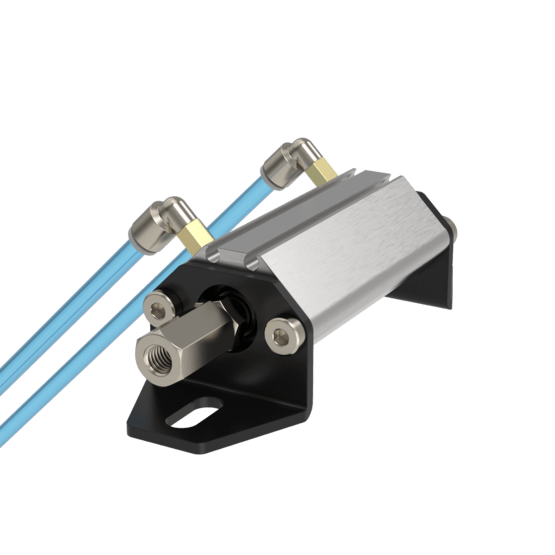
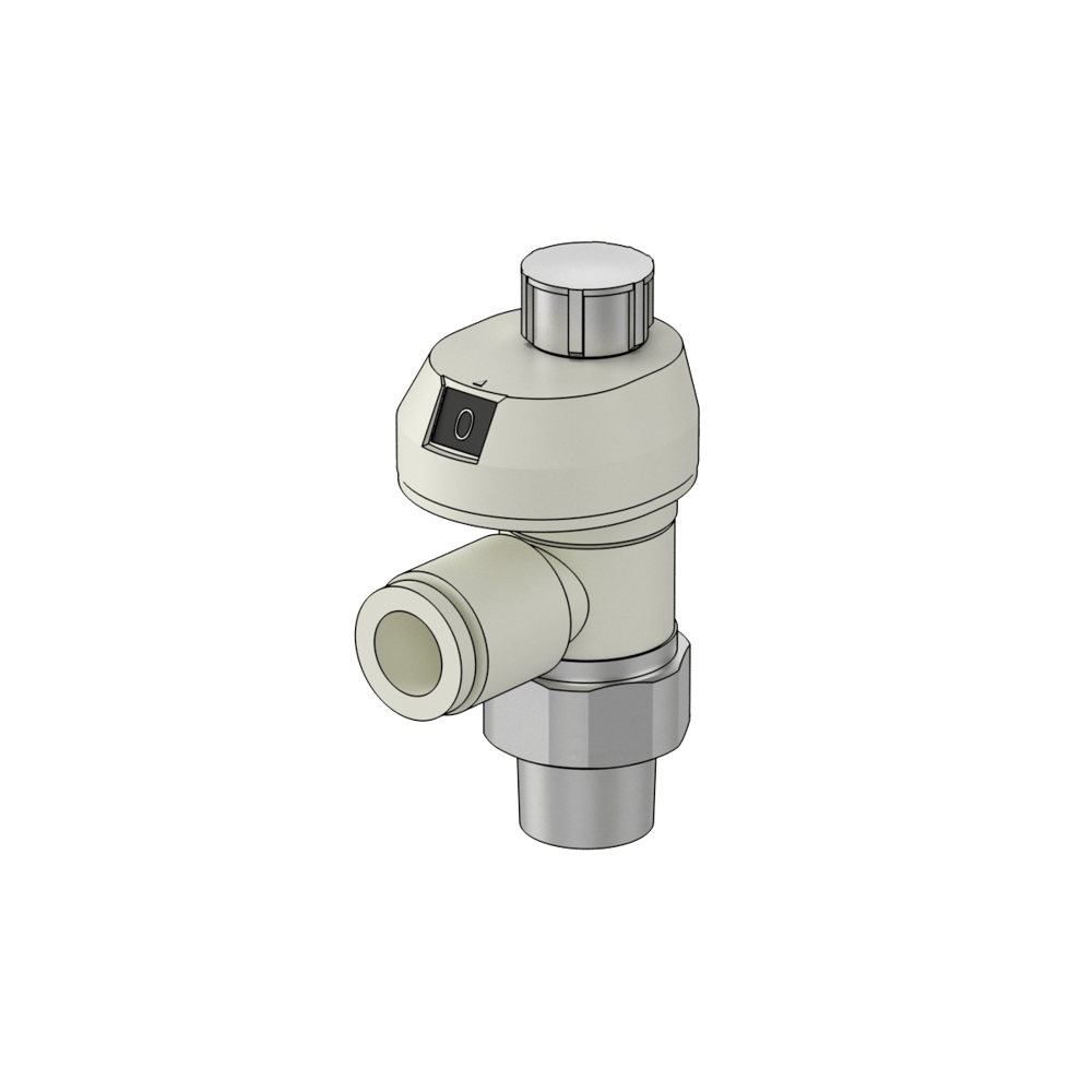
Normally Closed On/Off Valve (CE-AR-002-0000)
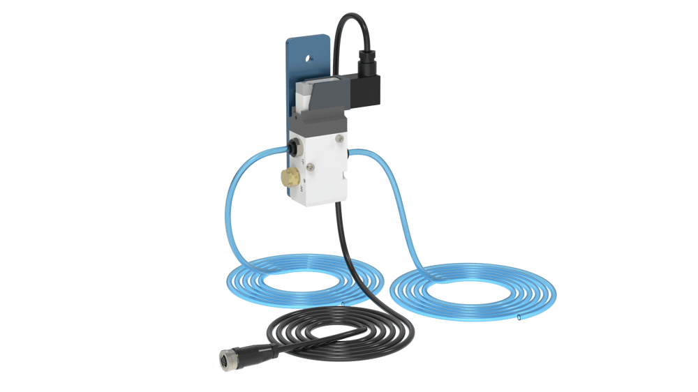 On/Off Valve | 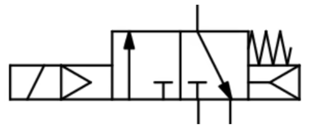 Symbol |
Specifications
Type of Actuation | Normally Closed (N.C.) |
Flow Coefficient Cv (Calculate Flow Rate here) | 2.1 |
Operating Temperature [°C] | -10 to 50 |
Maximum Operating Pressure [MPa] | 0.7 |
Minimum Operating Pressure [MPa] | 0.2 |
Control Voltage [V] | 24 |
Maximum (Peak) Power Consumption [W] | 1.55 |
Nominal Power Consumption [W] | 0.55 |
Enclosure Rating | IP65 |
Included Tubing | 12mm OD Polyurethane Tubing - 3 meters in length |
Wiring
Every On/Off Pneumatic Valve comes pre-wired with a M12 4-pin female connector. Since a Digital I/O Module v2 (CE-MD-001-0000__2) has 4 outputs ports, up to 4 valves can be controlled by a single module. Simply connect the M12 connector to any digital output port and start controlling the valve out-of-the-box.
IN Female M12 connector pinout
Pin | Description |
|---|---|
Pin 1 | NC |
Pin 2 | Input 24 VDC |
Pin 3 | Ground |
Pin 4 | NC |
Normally Open On/Off Valve (CE-AR-002-0006)
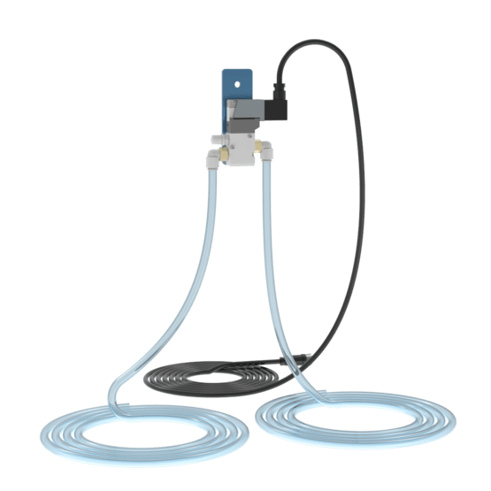 On/Off Valve | 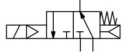 Symbol |
Specifications
Type of Actuation | Normally Open (N.O.) |
Flow Coefficient Cv (Calculate Flow Rate here) | 1.0 |
Operating Temperature [°C] | -10 to 50 |
Maximum Operating Pressure [MPa] | 0.7 |
Minimum Operating Pressure [MPa] | 0.2 |
Control Voltage [V] | 24 |
Maximum (Peak) Power Consumption [W] | 1.55 |
Nominal Power Consumption [W] | 0.55 |
Enclosure Rating | IP65 |
Included Tubing | 12mm OD Polyurethane Tubing - 4 meters in length |
Wiring
Every On/Off Pneumatic Valve comes pre-wired with a M12 4-pin female connector. Since a Digital I/O Module v2 (CE-MD-001-0000__2) has 4 outputs ports, up to 4 valves can be controlled by a single module. Simply connect the M12 connector to any digital output port and start controlling the valve out-of-the-box.
IN Female M12 connector pinout
Pin | Description |
|---|---|
Pin 1 | NC |
Pin 2 | Input 24 VDC |
Pin 3 | Ground |
Pin 4 | NC |
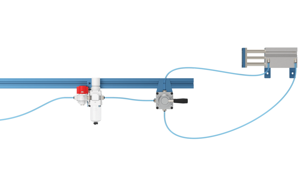
Manual Hand Valve (HW-AR-003-0000)
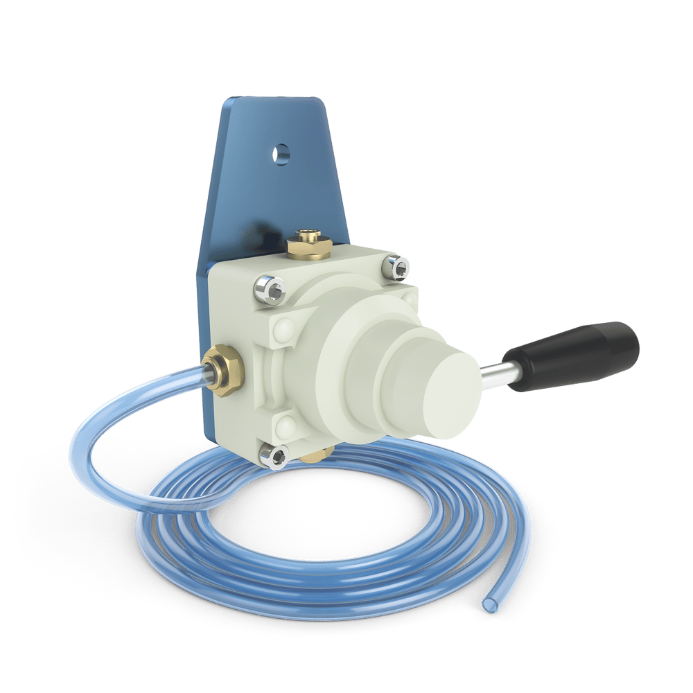 Manual Hand Valve | 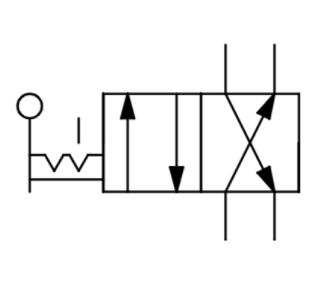 Valve Symbol |
Specifications
Flow Coefficient Cv per valve (Calculate Flow Rate here) | 1.5 |
Operating Temperature [°C] | -5 to 60 |
Maximum Operating Pressure [MPa] | 1.0 |
Positions | 2 |
Outlets | 6mm OD Push-to-Connect fittings to control Dual-Acting Actuators |
Included Tubing | 12mm OD Polyurethane Tubing - 3 meters in length |
20mm Bore, Non-Guided Actuators (MO-AR-001-0050)
 Actuator | 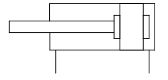 Symbol |
Specifications
Available Stroke Lengths [mm] | 50 |
Bore Size [mm] | 20 |
Operating Temperature [°C] | -5 to 60 |
Maximum Operating Pressure [MPa] | 1.0 |
Minimum Operating Pressure [MPa] | 0.05 |
Maximum Radial Load [N] | 3 |
Piston Speed [mm/s] | 5 to 500 |
Included Tubing | 6mm OD Polyurethane Tubing - 6 meters in length |
The actuator force is a function of its operating pressure. The theoretical output force can be calculated in the Actuator Force Calculation section below.
32 mm, Bore Non-Guided Actuators (MO-AR-001-0100/0200/0300)
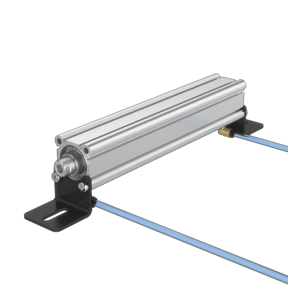 Actuator | Symbol |
Specifications
Available Stroke Lengths [mm] | 100, 200, 300 |
Bore Size [mm] | 32 |
Operating Temperature [°C] | -5 to 60 |
Maximum Operating Pressure [MPa] | 1.0 |
Minimum Operating Pressure [MPa] | 0.05 |
Maximum Radial Load [N] | 4 |
Piston Speed [mm/s] | 5 to 500 |
Included Tubing | 6mm OD Polyurethane Tubing - 6 meters in length |
The actuator force is a function of its operating pressure. The theoretical output force can be calculated in the Actuator Force Calculation section below.
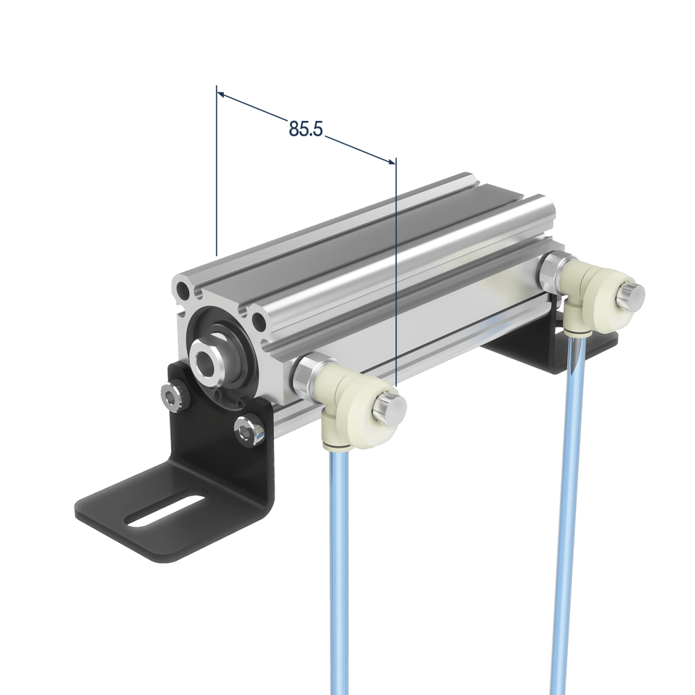
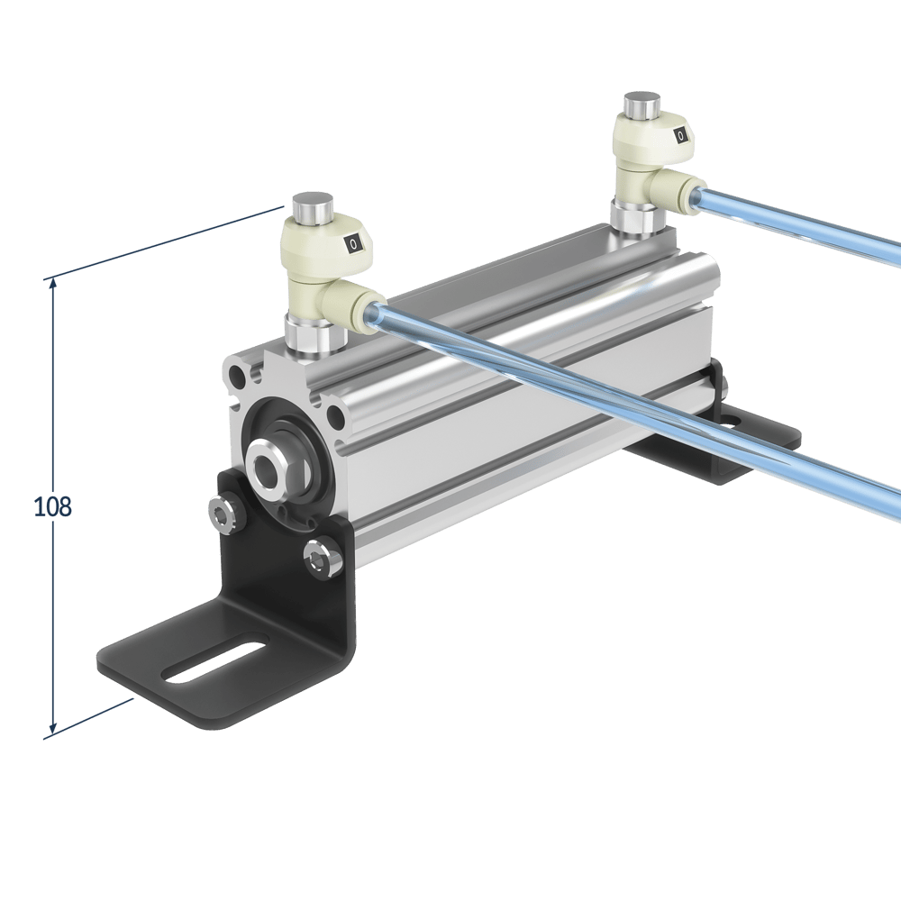
Guided Actuators (MO-AR-002-0100/0200/0300/0400)
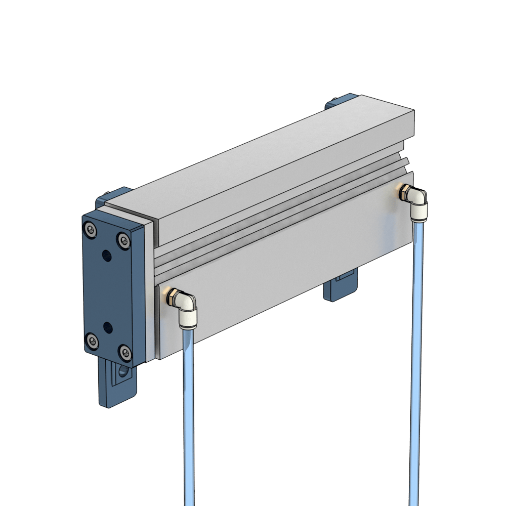 Actuator | 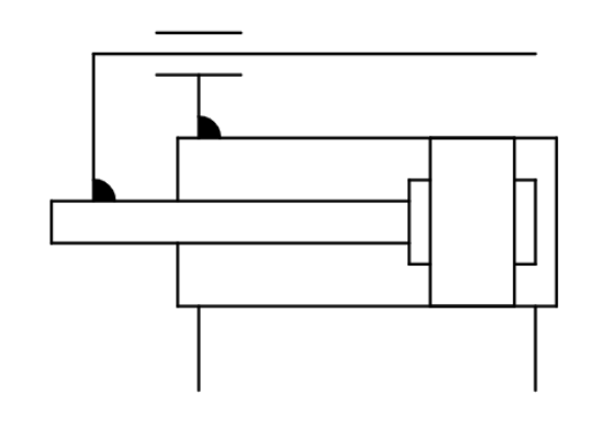 Symbol |
Specifications
Available Stroke Lengths [mm] | 100, 200, 300, 400 |
Bore Size [mm] | 25 |
Operating Temperature [°C] | -5 to 60 |
Maximum Operating Pressure [MPa] | 1.0 |
Minimum Operating Pressure [MPa] | 0.1 |
Maximum Radial Load [N] | 100mm stroke: 65 |
Piston Speed [mm/s] | 5 to 500 |
Included Tubing | 6mm OD Polyurethane Tubing - 6 meters in length |
The actuator force is a function of its operating pressure. The theoretical output force can be calculated in the Actuator Force Calculation section below.
Guided Actuators with Pinch Guarding (HW-AR-102-0100/0200/0300/0400)
 Guided Actuator | Symbol |
Specifications
Available Stroke Lengths [mm] | 100, 200, 300, 400 |
Bore Size [mm] | 25 |
Operating Temperature [°C] | -5 to 60 |
Maximum Operating Pressure [MPa] | 1.0 |
Minimum Operating Pressure [MPa] | 0.1 |
Maximum Radial Load [N] | 100mm stroke: 65 |
Piston Speed [mm/s] | 5 to 500 |
Included Tubing | 6mm OD Polyurethane Tubing - 6 meters in length |
The actuator force is a function of its operating pressure. The theoretical output force can be calculated in the Actuator Force Calculation section below.
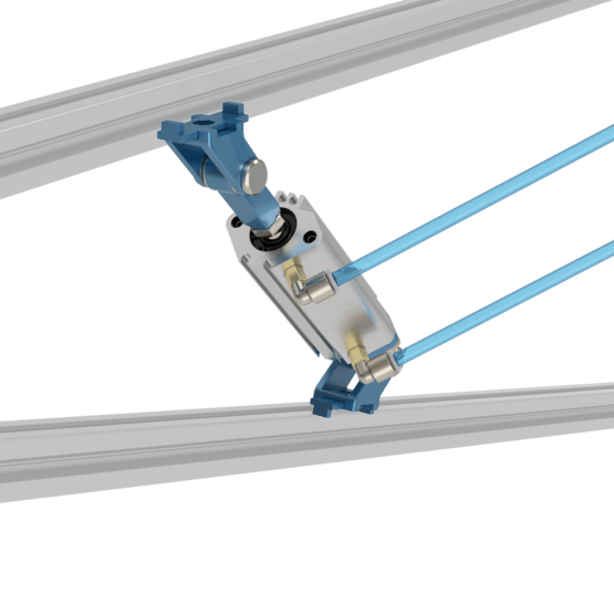
20mm Bore, Pivoting Non-Guided Actuators (MO-AR-003-0050)
 Actuator | Symbol |
Specifications
Available Stroke Lengths [mm] | 50 |
Bore Size [mm] | 20 |
Operating Temperature [°C] | -5 to 60 |
Maximum Operating Pressure [MPa] | 1.0 |
Minimum Operating Pressure [MPa] | 0.05 |
Maximum Radial Load [N] | 6 |
Piston Speed [mm/s] | 5 to 500 |
Included Tubing | 6mm OD Polyurethane Tubing - 6 meters in length |
The actuator force is a function of its operating pressure. The theoretical output force can be calculated in the Actuator Force Calculation section below.
Additionally, the pivoting non-guided cylinders have rotational limitations on both front and back clevis brackets. They both have a pivoting range of 225°.
|
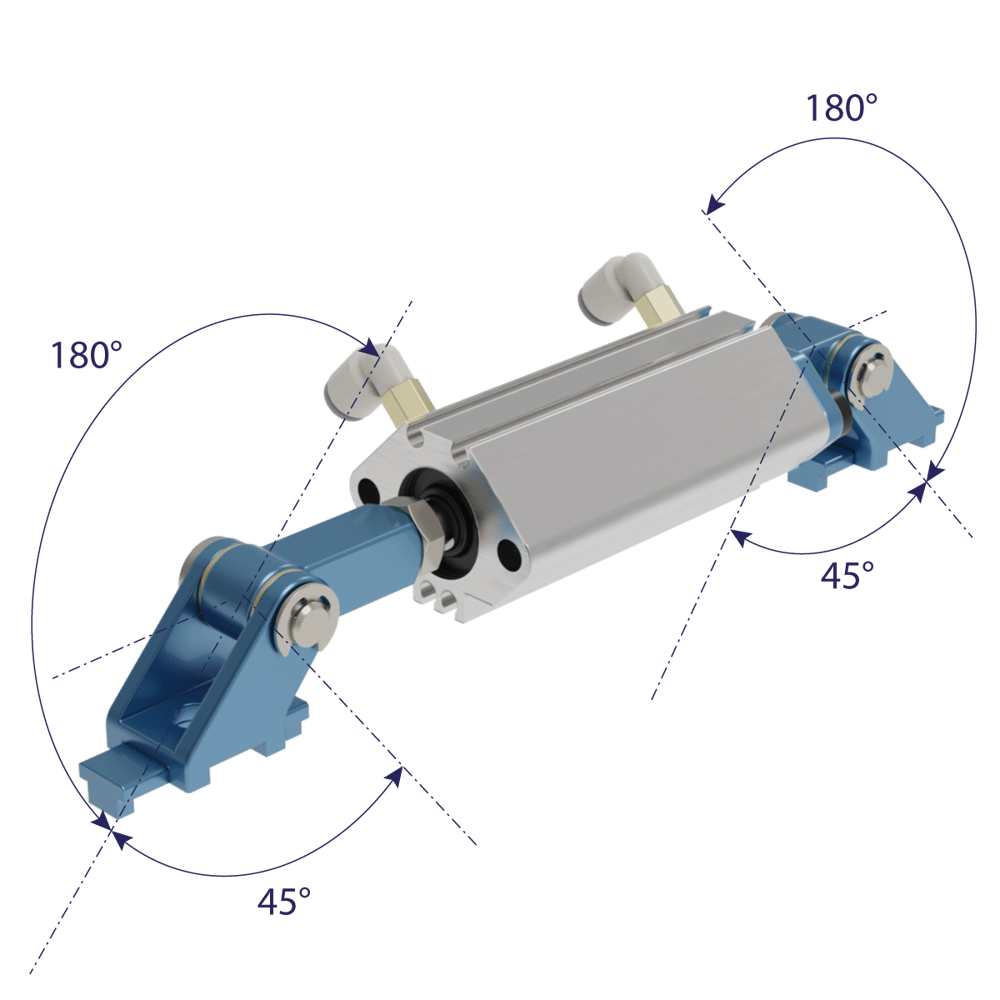
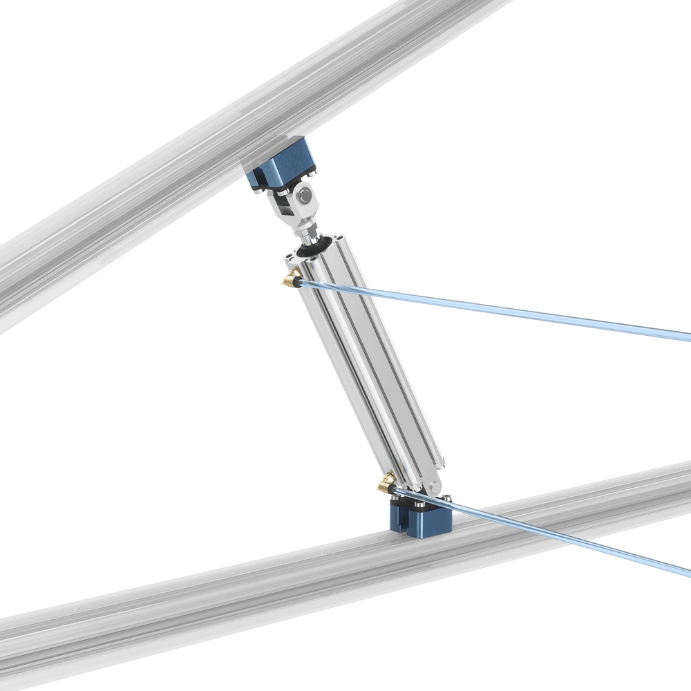
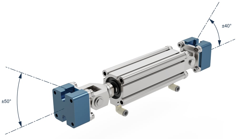
32mm Bore, Pivoting Non-Guided Actuators (MO-AR-003-0100/0200/0300)
 Actuator | Symbol |
Specifications
Available Stroke Lengths [mm] | 100, 200, 300 |
Bore Size [mm] | 32 |
Operating Temperature [°C] | -5 to 60 |
Maximum Operating Pressure [MPa] | 1.0 |
Minimum Operating Pressure [MPa] | 0.05 |
Maximum Radial Load [N] | 15 |
Piston Speed [mm/s] | 5 to 500 |
Included Tubing | 6mm OD Polyurethane Tubing - 6 meters in length |
The actuator force is a function of its operating pressure. The theoretical output force can be calculated in the Actuator Force Calculation section below.
Additionally, the pivoting non-guided cylinders have rotational limitations on both front and back clevis brackets. The front piston clevis mount of the cylinder is limited to a ± 50° range of motion, while the back clevis mount is limited to ± 40°.
|
Guided Actuator for Box Stopping (MO-AR-007-0050)
 Box Stopper | Symbol |
Specifications
Available Stroke Lengths [mm] | 50 |
Bore Size [mm] | 50 |
Operating Temperature [°C] | -5 to 60 |
Maximum Operating Pressure [MPa] | 1.0 |
Minimum Operating Pressure [MPa] | 0.1 |
Maximum Radial Load [N] | 1472 (equivalent to 150kg of accumulated boxes) |
Piston Speed [mm/s] | 5 to 500 |
Included Tubing | 6mm OD Polyurethane Tubing - 6 meters in length |
The actuator force is a function of its operating pressure. The theoretical output force can be calculated in the Actuator Force Calculation section below.
Guided Actuator for Pallet Stopping (MO-AR-008-0050)
 Pallet Stopper | Symbol |
Specifications
Available Stroke Lengths [mm] | 100, 200 |
Bore Size [mm] | 25 |
Operating Temperature [°C] | -5 to 60 |
Maximum Operating Pressure [MPa] | 1.0 |
Minimum Operating Pressure [MPa] | 0.1 |
Maximum Radial Load [N] | 14715 (equivalent to a 1500kg pallet) |
Piston Speed [mm/s] | 50 to 400 |
Included Tubing | 6mm OD Polyurethane Tubing - 6 meters in length |
The actuator force is a function of its operating pressure. The theoretical output force can be calculated in the Actuator Force Calculation section below.
Position Sensor (CE-SN-008-0001__2)
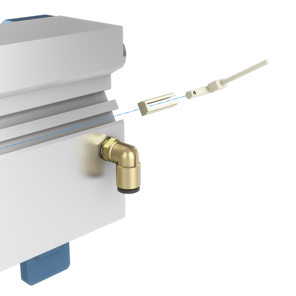
When confirmation of the actuator position is needed, a Normally Closed (N.C.) position sensor (CE-SN-008-0001__2) can be easily slid into any groove on the pneumatic actuator and secured in place using a 1mm precision flat screwdriver. It accurately senses the magnetic field of the piston as it passes beneath the sensor and a built-in red LED illuminates when the sensor output is active.
|
Each position sensor can be directly connected to a Digital I/O Module v2 input port (CE-MD-001-0000__2), up to 4 sensors per module.
|
The guided actuators MO-AR-002-0100/0200 and MO-AR-008-0050 require an adapter to properly secure the position sensor in place. An adapter is included with each sensor.
|
Position sensors (M12, A-coded, male cable end) :
Pin | Description |
|---|---|
1 | 24VDC |
2 | Sensor signal output |
3 | Ground |
4 | NC |
Position sensors (M12, A-coded, no cable) :
Pin | Description |
|---|---|
1 | 24 VDC |
2 | Sensor signal output |
3 | Ground |
4 | NC |
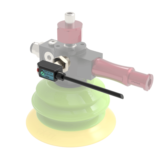
Vacuum Switch (CE-SN-009-0001)
When confirmation of vacuum level on a suction cup is required, a vacuum switch (CE-SN-009-0001) can easily be installed on one of the vacuum ports of a Piab VGS 3010 venturi. It detects if the user-set threshold is met It accurately senses the magnetic field of the piston as it passes beneath the sensor and a built-in red LED illuminates when the sensor output is active.
Each vacuum switch can be directly connected to a Digital I/O Module v2 input port (CE-MD-001-0000__2), up to 4 sensors per module.
|
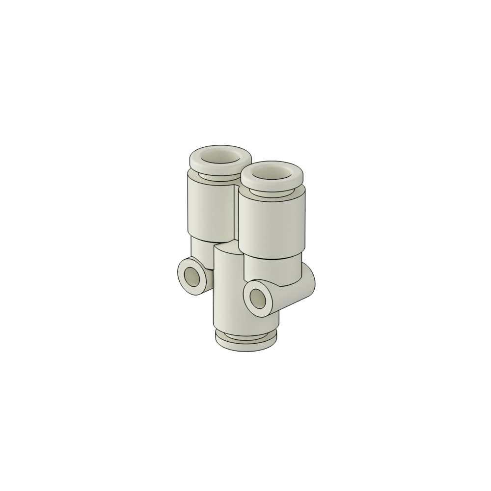
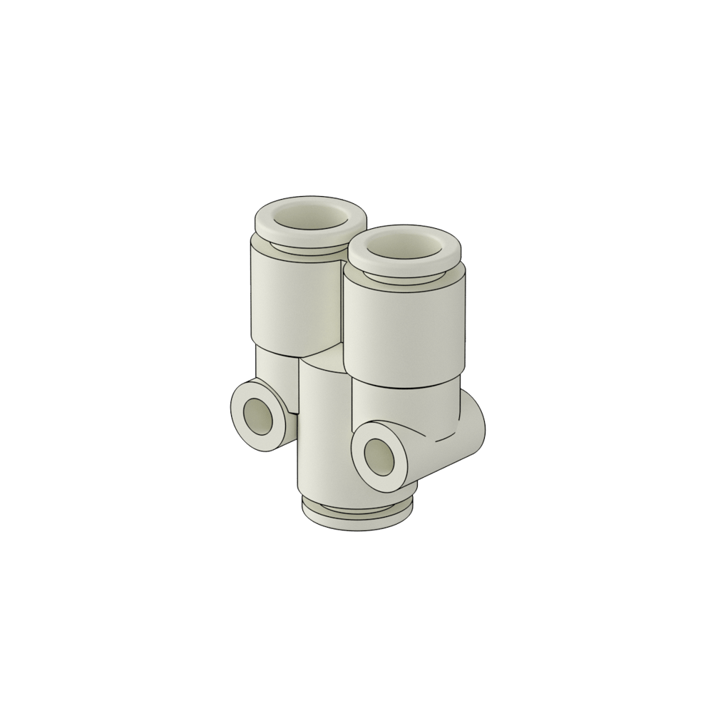
Accessories
Vention’s Pneumatic Ecosystem also includes a variety of accessories for different use cases.
Use of Speed Controllers
The 6mm 90 Degree One-touch Fitting to 1/8in RC with Speed Controller (HW-AR-002-0007) and 6mm Inlet/Outlet One-Touch Fitting with Speed Controller (HW-AR-002-0013) features a numeric indicator representing a specific level of flow control for cylinders. This fitting can be used to slow down and control the speed of the push and pull movement of our dual action cylinders. The indicator can be used to synchronize multiple cylinders to the same speed.
Note: HW-AR-002-0007 replaces the pre-installed 90-degree fittings most of our cylinders. When installing the speed controller fittings, the cylinder must be turned either 90 or 180 degrees with respect to the mounting brackets as the fittings do not fit underneath when mounted. Use an adjustable wrench to properly install the fittings. These fittings are not compatible when used with some of the guided actuators with pinch guarding, specifically MO-AR-007-0050 and HW-AR-102-0300/0400. Additionally MO-AR-001-0050 and MO-AR-003-0050 (20mm bore actuators) as they use M5 fitting threads. For all of these, an inline one-touch speed controller (HW-AR-002-0013) must be used.
|
|
Assembly Instructions
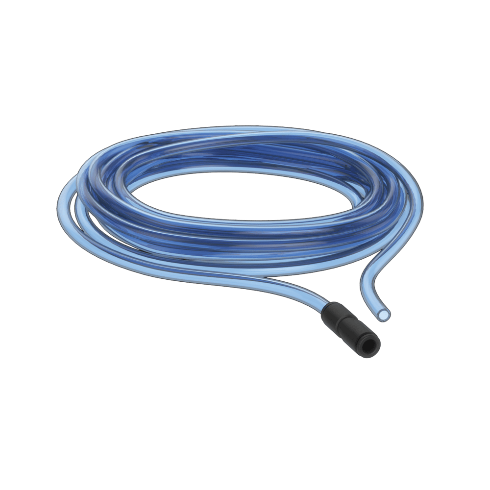
Note: All air supply tubes have an 12 mm outer diameter, whereas all actuator tubes have a 6 mm outer diameter.
When connecting your pneumatic system:
Make sure the emergency shutoff valve is turned to the EXH (exhaust) position
Connect the filter/regulator unit’s outlet to the manifold’s inlet port using the provided 8 mm tubing
Connect the unaltered end of the provided supply line to the shutoff valve’s inlet
Attach the provided quick-connect fitting to the supply line, and connect the end of the fitting to your air supply
If you don’t have an air-preparation station, simply connect the unaltered end of the provided supply line to the manifold’s inlet
Every valve features two ports which correspond respectively to the actuator’s push and pull actions
Connect the valve ports on the manifold to the actuator ports using the provided 6 mm tubing
Test the actuator. If the direction of action is the opposite of what is desired, simply swap the tubes using the one-touch fittings
Non-Guided Cylinder Assembly
|
Guided Cylinder Assembly
|
Manual Valve with Guided Cylinder Assembly
|
On/Off Valve Assembly
|
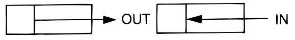
Actuator Force Calculation
The effective pushing and pulling force of all cylinders can be calculated as follows:
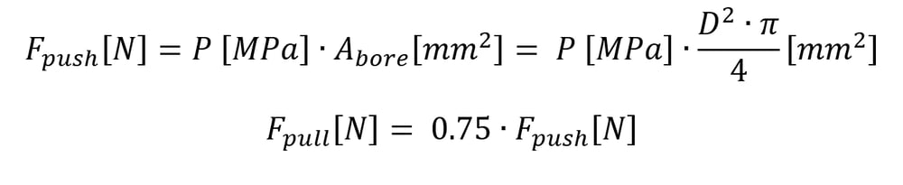
Pressure P [MPa] | 0.3 | 0.5 | 0.7 |
20mm Bore Non-Guided Cylinder Pushing Force (OUT) [N] | 94 | 157 | 220 |
20mm Bore Non-Guided Cylinder Pulling Force (IN) [N] | 71 | 118 | 165 |
32mm Bore Non-Guided Cylinder Pushing Force (OUT) [N] | 241 | 402 | 563 |
32mm Bore Non-Guided Cylinder Pulling Force (IN) [N] | 181 | 302 | 422 |
25mm Bore Guided Cylinder Pushing Force (OUT) [N] | 147 | 246 | 344 |
25mm Bore Guided Cylinder Pulling Force (IN) [N] | 113 | 189 | 265 |
50mm Bore Guided Cylinder Pulling Force (OUT) [N] | 589 | 982 | 1374 |
50mm Bore Guided Cylinder Pulling Force (IN) [N] | 513 | 855 | 1196 |
80mm Bore Guided Cylinder Pulling Force (OUT) [N] | 1508 | 2513 | 3519 |
80mm Bore Guided Cylinder Pulling Force (IN) [N] | 1394 | 2323 | 3252 |
Flow Rate Calculation
Your system’s maximum Flow Rate Qv in standard cubic feet per minute (scfm) can be calculated by deviding the Flow Coefficient Cv by a predertermined conversion factor based on pressure as seen in the table below.
Pressure P [MPa] | 0.276 (40 psi) | 0.345 (50 psi) | 0.412 (60 psi) | 0.483 (70 psi) | 0.552 (80 psi) | 0.621 (90 psi) | 0.690 (100 psi) |
Conversion Factor | 0.0370 | 0.0312 | 0.0270 | 0.0238 | 0.0212 | 0.0192 | 0.0177 |
When calculating the maximum flow rate, it is important that the lowest Cv value is used as it is the limiting factor. For example, to determine the maximum flow rate through a system that utilizes an On/Off Valve (CE-AR-002-0000) and an Air Preparation Station (CA-AP-001-0001), the lowest Cv is 2.1. Assuming the system’s pressure is set to 0.55 MPa (80 psi), the following calculation must be done:
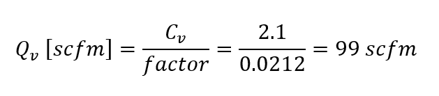
Note: This general rule applies at standard air temperature (20°C) and pressure (101.3 kPA or 14.7 psi). It provides an approximation of air flow rate values, not an exact measurement.