Overview
This datasheet covers the different O-ring roller conveyors available at Vention, as well as their various applications for automation in different industries. It also details the technical specifications of each conveyor as well as their required calculations. The ending of the document focuses on the installation of the conveyors and provides a guide to configuring it with a simple and efficient code-free conveyor application example.
O-ring roller conveyor sections
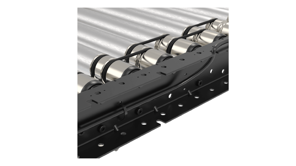
Vention’s pre-assembled conveyor sections were designed in a simple and smart way to ensure an easy initial setup and long-lasting performance. From a simple straight segment to a full conveyor application, it has never been so easy to design a conveyor system. All our sections are compatible with each other, as well as our full Vention’s ecosystem.
All sections are equipped with provisions to add sensors and cable management cut-outs and are compatible with many Vention accessories, including modules, leg adjustment, angle adjustment, pneumatic pushers, and end stops.
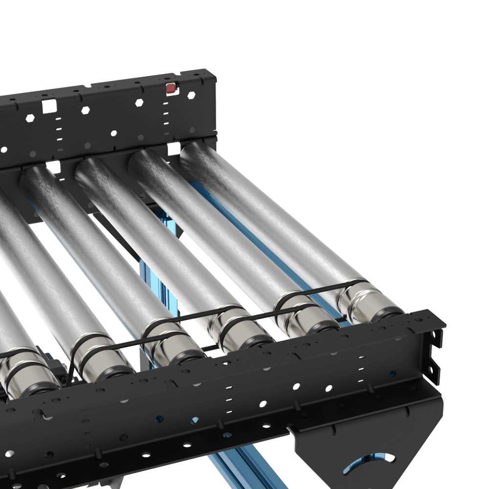
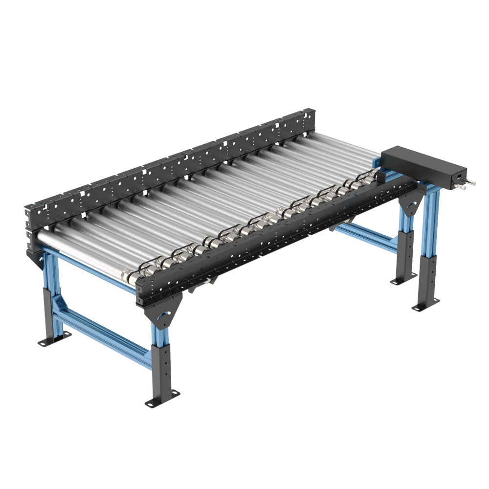
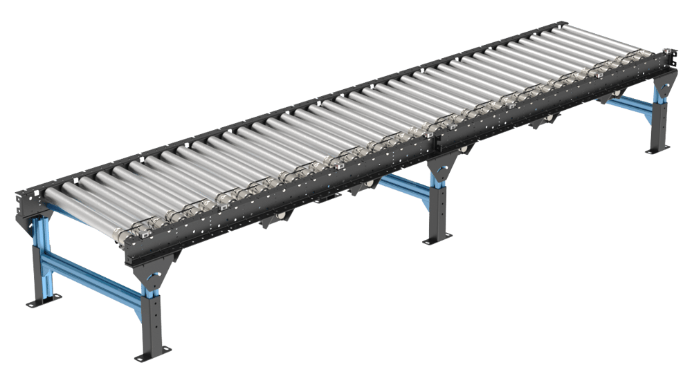
Powered straight sections
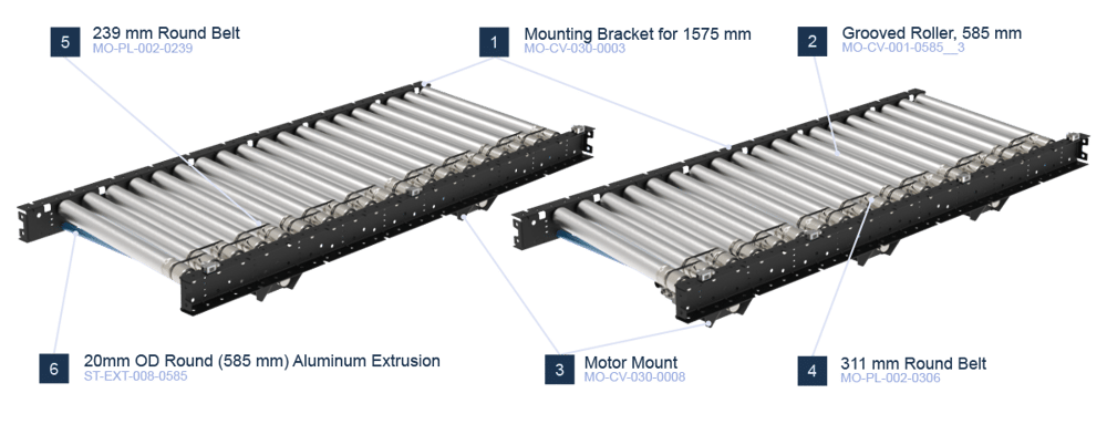
Our straight sections are available in 3 width (405, 585 and 945 mm) and 2 lengths (630 and 1575 mm). It is also possible to choose between having 2 or 3 zones for the 1575 mm sections, depending on the required performance. The table below shows all SKUs of straight sections.
Note: Width is the distance between the c-channels, called between frames width (BF width)
Part Number | Width (mm) | Number of zones | Length (mm) | Number of rollers |
|---|---|---|---|---|
405 | 2 | 1575 | 20 | |
3 | 1575 | 20 | ||
1 | 630 | 8 | ||
585 | 2 | 1575 | 20 | |
3 | 1575 | 20 | ||
1 | 630 | 8 | ||
945 | 2 | 1575 | 20 | |
3 | 1575 | 20 | ||
1 | 630 | 8 |
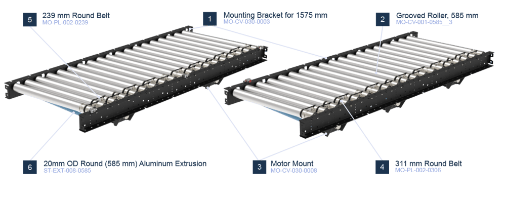
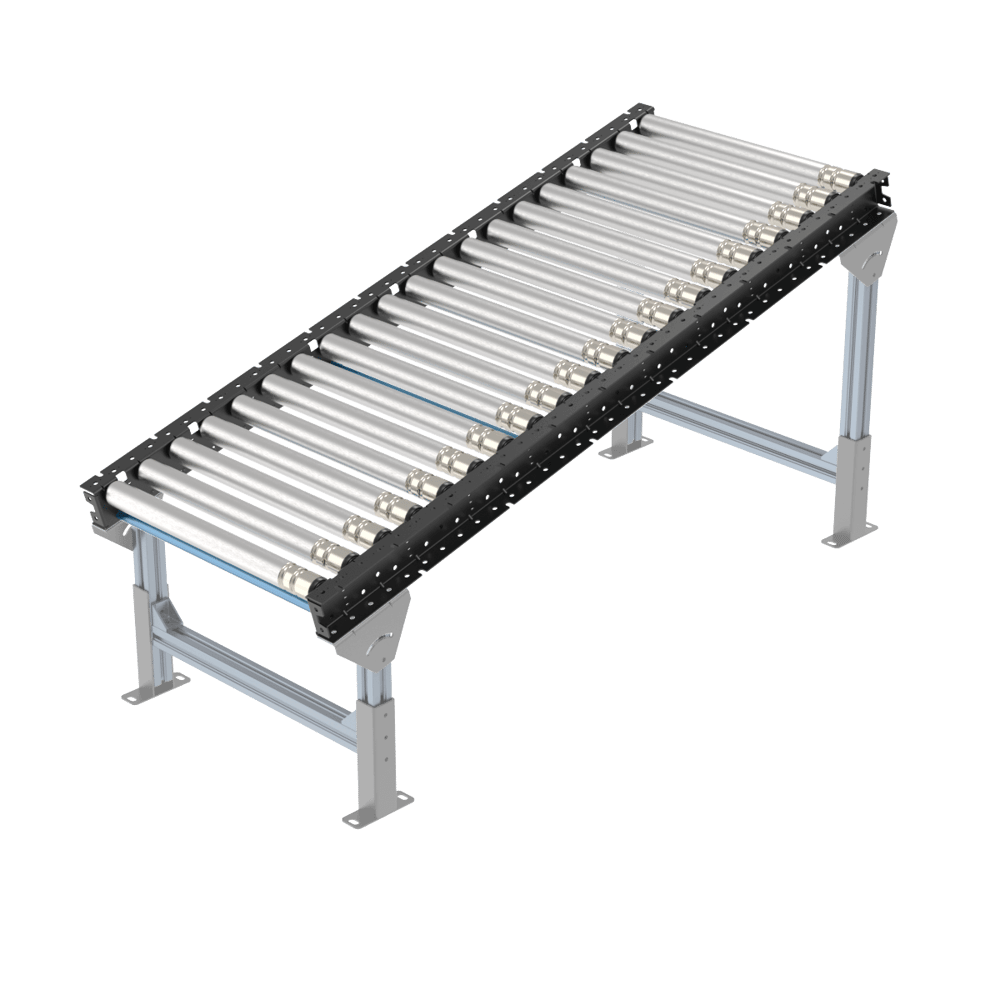
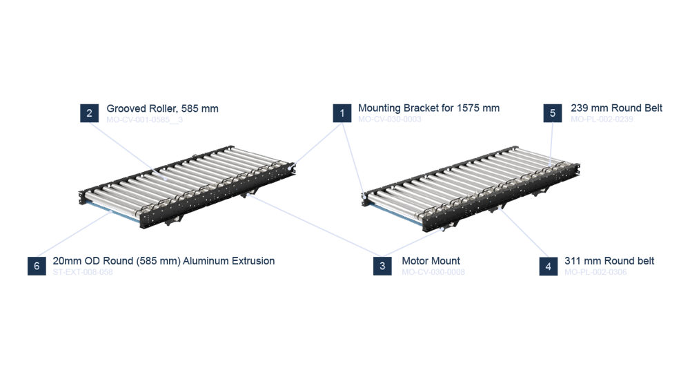 Powered 1575 mm straight sections |
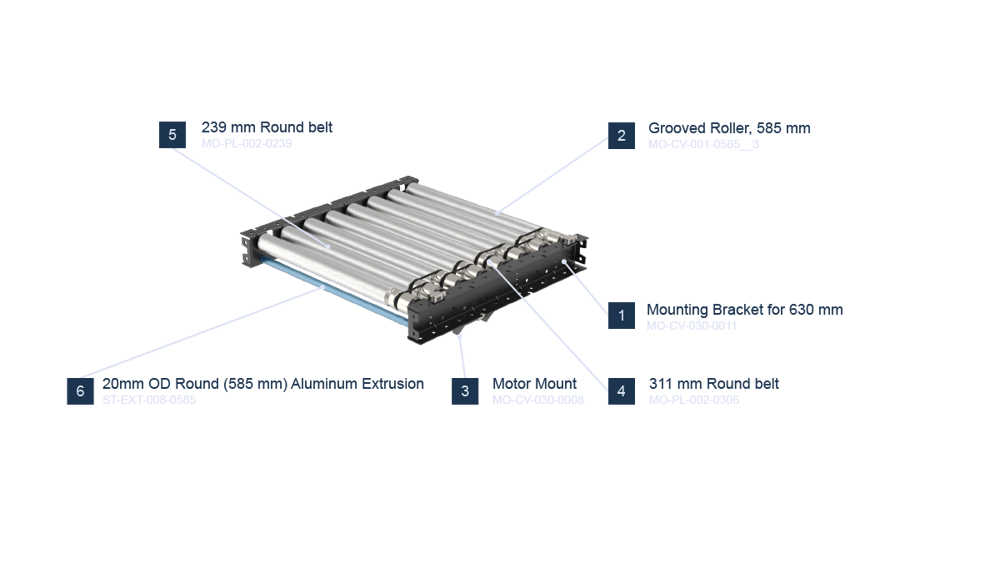 Powered 630 mm section |
Powered curved section
Tapered rollers are used for the curved sections of our o-ring roller conveyor family. These one zone, 45° sections offer a quick and easy conveyor turn solution. Simply have two of these together to complete a 90° turn with 2 zones. Table below shows all SKUs of curved sections.
Part Number | Width (mm) | Angle (°) | Number of zones | Number of rollers |
|---|---|---|---|---|
405 | 45 | 1 | 10 | |
585 | ||||
945 |
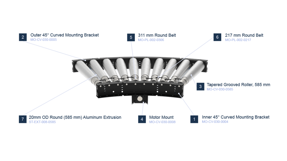 MO-CV-030-0012 Curved Powered Section Example |
Skewed sections
Vention’s new roller conveyor family also offers a set of skewed conveyors, to fulfill any additional box movement needed for palletizing or any other application they might be required. The 12 sections below allow left and right directions with 2 or 3 zones. The lateral movement of these conveyors is calculated based on the skewed angle (α) and the total length (L) of the conveyors using the following formula:
For example for 585 mm skewed conveyor the lateral movement along the length (1575 mm) is:
Table below shows all SKUs of skewed sections.
Part Number | Width (mm) | Direction | Number of Zones | Length (mm) | Number of Rollers | Skewed Angle (°) | Lateral Movement Along Length (mm) |
|---|---|---|---|---|---|---|---|
405 | Right to Left | 2 | 1575 | 19 | 10.8 | 300 | |
3 | |||||||
Left to Right | 2 | ||||||
3 | |||||||
585 | Right to Left | 2 | 7.6 | 210 | |||
3 | |||||||
Left to Right | 2 | ||||||
3 | |||||||
945 | Right to Left | 2 | 4.7 | 130 | |||
3 | |||||||
Left to Right | 2 | ||||||
3 |
 Right to left powered skewed section |
 Left to right powered skewed section |
Unpowered sections
Finally, if no power is required for some applications, an unpowered straight section can be used. These unpowered sections can be used as gravity conveyors. Table below shows the 6 different unpowered sections which come in 3 widths (405, 585 and 945 mm) and 2 lengths (630 and 1575 mm). Table below shows all SKUs of unpowered sections:
Part Number | Width (mm) | Length (mm) | Number of rollers |
|---|---|---|---|
405 | 1575 | 20 | |
630 | 8 | ||
585 | 1575 | 20 | |
630 | 8 | ||
945 | 1575 | 20 | |
630 | 8 |
 1575 mm gravity section | 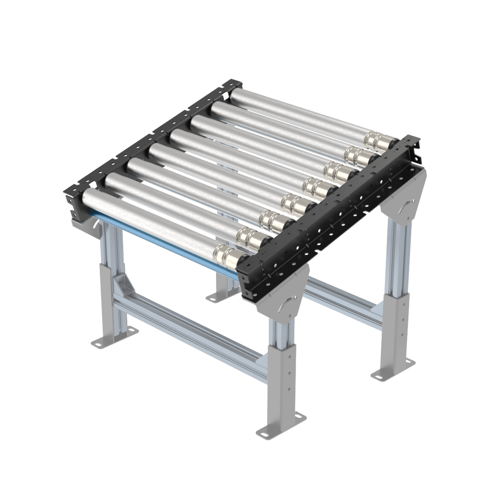 630 mm gravity section |
Applications
Conveyors are used to move loads from one point to another. Our O-ring conveyor family offers possibilities to create applications that vary from simple gravity conveyors to complex systems with indexing and zero pressure accumulation. Visit our design library for sample designs of different applications. Here are a few examples:
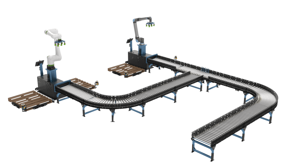 Dual palletizer with sorting/pusher |
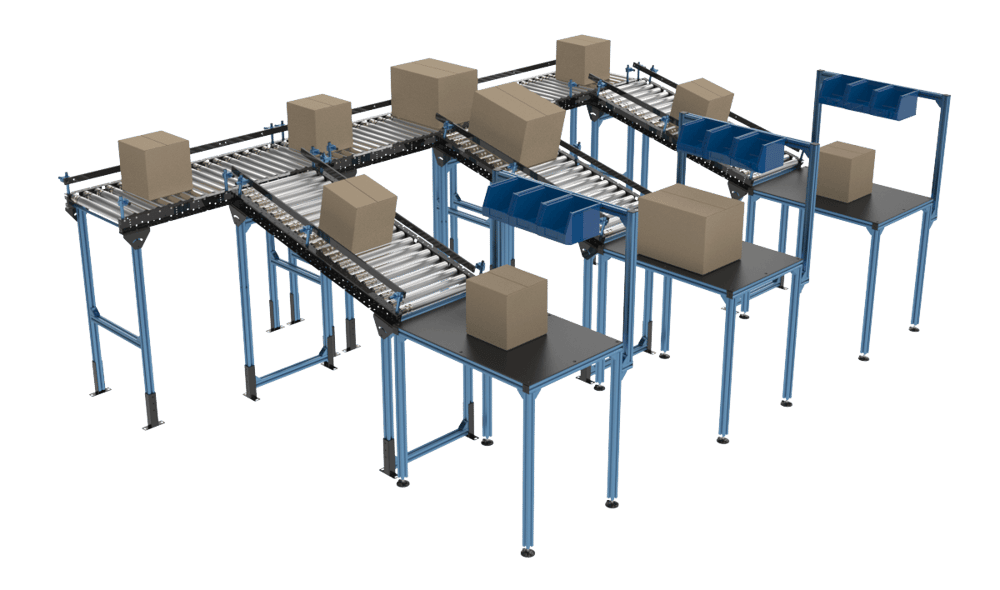 Sorting station |
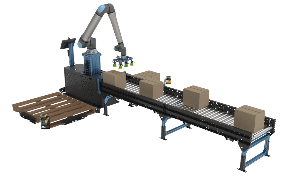 Single palletizer with skewed section |
To build a conveyor using our Machine Logic code-free conveyor application example, consult the following guide and download the Python file to generate the application.
Technical Specifications
Section types | powered straight, powered curved, powered skewed, unpowered straight |
Application Type | zero pressure accumulation, conveying |
Lengths | 630, 1575 mm |
Roller Diameter | 50 mm |
Rollers Pitch | 78.75 mm |
Roller Widths/Between Frame width (mm) | 405, 585, 945 mm |
Max Payload Per Zone for Transit (Non-Accumulation)* | 40 kg |
Max speed | 450 mm/s (90 ft/min) |
Min speed | 150 mm/s (30 ft/min) |
Displacement ratio | 92.82 mm per revolution |
Min box length | 160 mm |
Roller material | zinc plated steel |
Max angle of powered inclined conveyor | 10° (when load going upward) |
Max load of powered inclined conveyor with 10° angle | 15 kg per zone (when load going upward) |
*Note: the rated payload is for a cardboard box. More rigid bins or crates may increase the payload while more compliant containers such as weak boxes or bags will drastically reduce this capacity. Note that the o-ring conveyor is not intended for pressure accumulation. For all accumulation applications refer to the Poly-V conveyor product.
Accessories
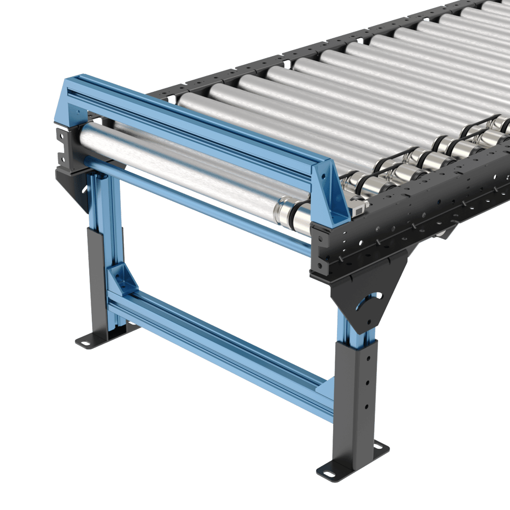
1) Leg adjustments
The two following leg and conveyor adjustments are available and fully compatible with this o-ring conveyor family.
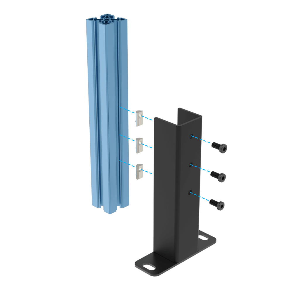
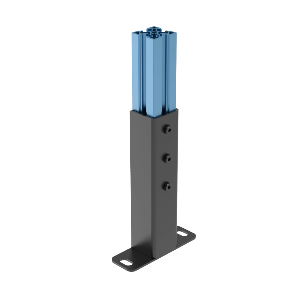
Height Adjustment bracket (MO-CV-030-0007): This bracket allows a quick and simple way to adjust the conveyor to any existing equipment. The max translation is 150 mm
Angle Adjustment bracket (MO-CV-030-0006__2): The angle adjustment bracket is a key part for all gravity conveyors, while also allowing to adjust the conveyor to existing equipment.
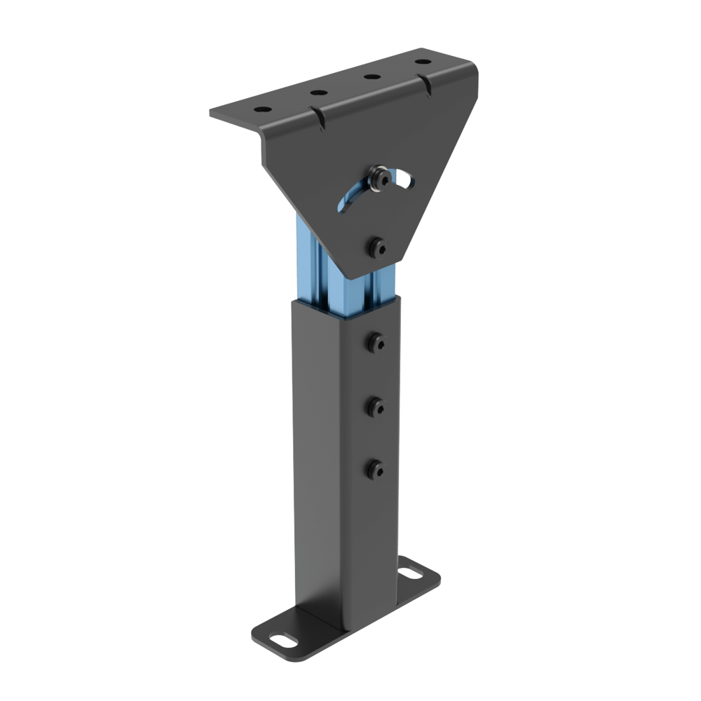
Height and angle adjustments
2) Modules, sensors, and cable management
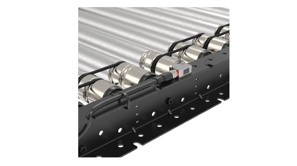
Sensor Mounts
Each C-channel of Vention’s O-ring conveyor family is equipped with specific placement for sensors, making it easy to install without additional hardware. It is also possible to use any existing hole, with the addition of the sensor bracket CE-HW-001-0003 or the fully enclosed bracket MO-CV-030-0023. Along with optional reflector mounts MO-CV-030-0024 for mounting on top of the conveyor or MO-CV-030-0054 for mounting a reflector in a c-channel
I/O and E-Stop Module
There are several options for installing the I/O and E-Stop modules, either using the vertical extrusions for the legs or using a simple extrusion structure attached beneath the conveyor c-channel, as shown below.
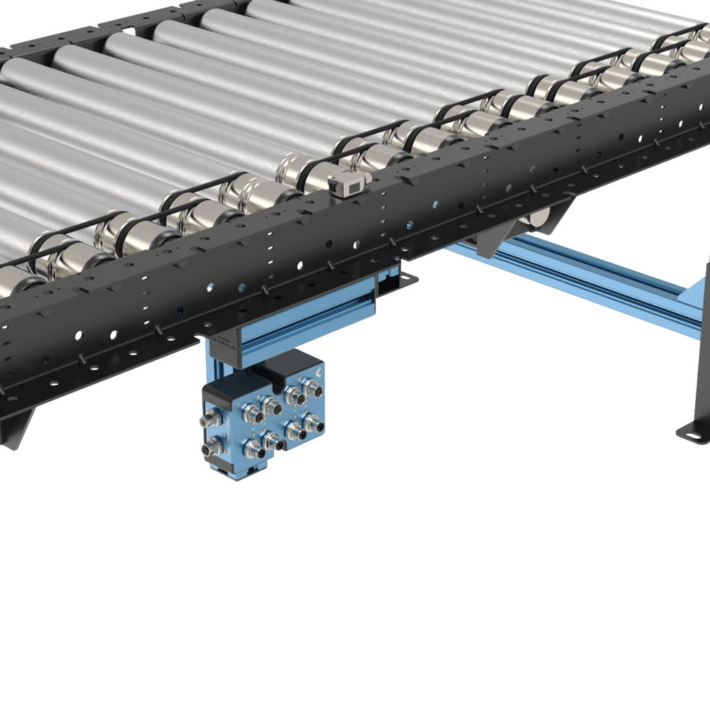 Module and sensor installation |
Cable Management
The C-Channel brackets is equipped with cutouts to allow easy cable management coming from sensors, modules, and motor cables to prevent chaffing and offer a clean integration setup. It is also possible to use zip ties to secure cables using the designated holes along the C-Channel.
|
|
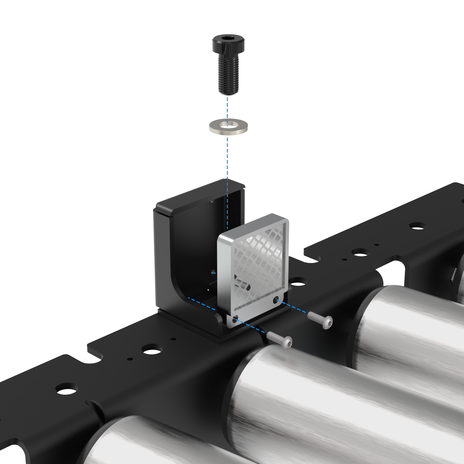
3) Side guard
a) Mounting bracket as side guard
The C-channels mounting the rollers are versatile and can also be used as a guiding system on all sections. The c-channel can simply be superposed over the actual conveyor section. Associated fasteners are included in each C-Channel to ensure a safe installation.
.png) Straight mounting bracket as side guide | 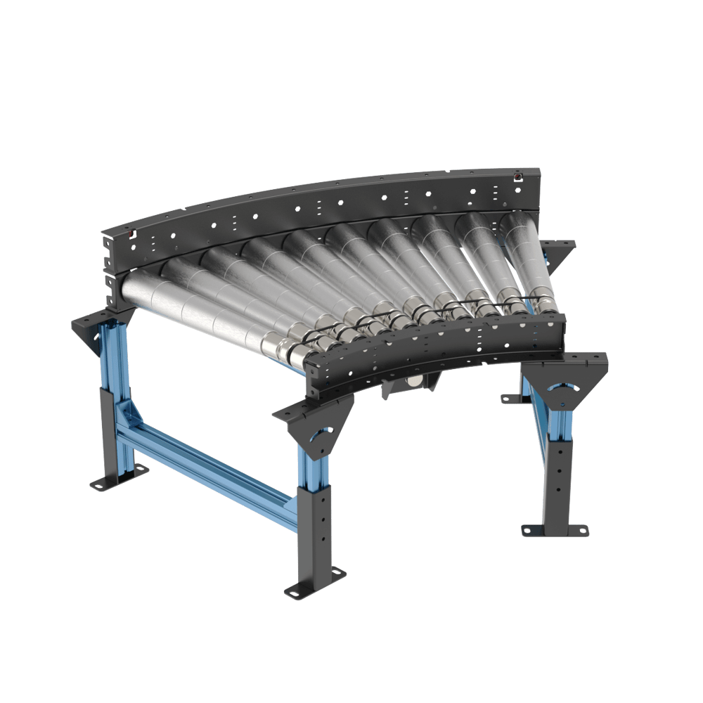 Curve mounting bracket as side guard |
Another great perk of having a channel as a side guide is being able to install sensors underneath the top bracket in its designated cutouts. This will allow maximum protection of the sensor.
 Sensor behind guard | 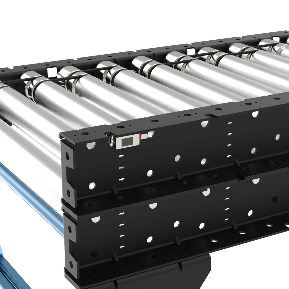 Sensor behind guard (other side) |
b) Flexible guides (straight sections only)
Flexible guards (ST-PN-020-2295) can be cut to the required length to be able to direct, index or funnel boxes along a conveyor during material handling operations. Using our well-known round extrusion, the flexible guide provides an adjustable solution for flexible guide. For more details, refer to the Flexible Conveyor Guide section of the Material Handling Datasheet.
4) Pneumatic pushers
In palletizing applications, to have the box on a certain location on the conveyor at the end of the line and close to the robot to pick up, a pneumatic pusher is used to push the box to the side of the conveyor. It is possible to install the pneumatic pusher in a simple way on Vention’s new o-ring conveyors. Follow these steps for a quick and easy design:
Install a short 45x45 extrusion on top of the conveyor c-channel using associated fasteners from the conveyor
M8 serrated nuts (HW-FN-031-0002)
M8x18 mm screws (HW-FN-003-0018) and
M8 split washers (HW-WS-001-1003)
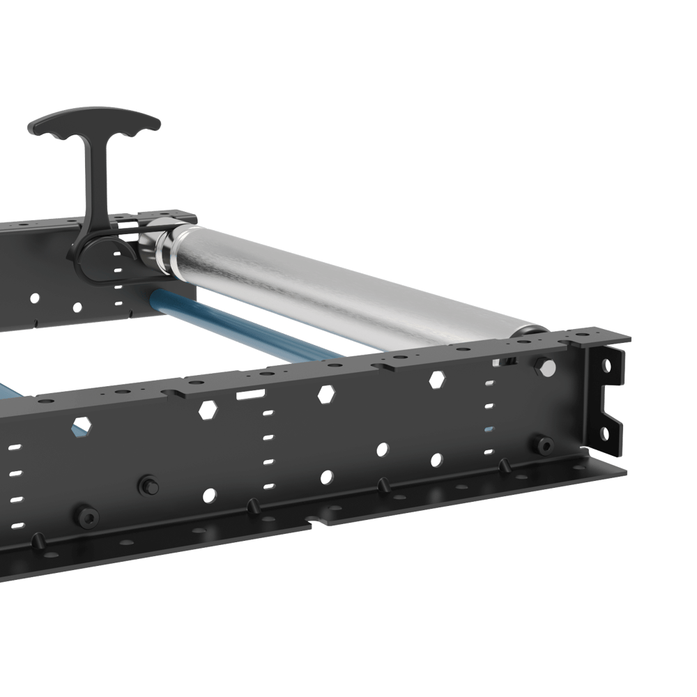
Design and install an additional leg made of extrusion, with the same height as the conveyor. The below image shows a T-shaped leg to hold the pusher.
Install the pusher on top of the conveyor and the additional leg.
Pneumatic pusher installation
5) End Stop
An end stop can be easily made out of two GP gussets (ST-GP-003-0005 or ST-GP-003-0001) and a 45x45 mm extrusion between them. It can be installed on top of the conveyor c-channels using the following fasteners:
M8x18 mm screws (HW-FN-003-0018) provided with the gussets
M8 Serrated Flange Locknut (HW-FN-031-0002) provided with the conveyor.
End Stop example
6) Motor Shaft Cover
This cover (MO-CV-030-0022) can be installed beneath the conveyor c-channel and in front of each motor as a safety guard In order to protect people from touching the motor shaft. It has a slot on top which makes it compatible with all straight, skewed and curved sections.
O-Ring Conveyor Pinch Points
The Smart O-Ring Conveyor system is engineered for intrinsic safety. Unlike high-torque power transmission systems (such as Poly-V or Chain drives), the O-ring drive mechanism leverages the physical limits of friction based transmission and highly elastic belts to mitigate mechanical hazards.
Frictional Slip-to-Stall Mechanism
The primary safety feature of the O-ring drive is its torque-limited interface. The round urethane belts rely on the friction generated between the belt and the roller due to the tension in the belts. This leads to a relatively low torque transmission and therefore a low stall point which is considered intrinsically safe. In other words, the o-ring belts will slip on the rollers before any part of the human body can be damaged. The O-ring immediately slips within the groove. This decoupling prevents the motor's full torque from being transferred to the obstruction, preventing injury.
Elastic Deformation & Displacement
O-rings are high-elasticity components with a high "stretch-to-break" ratio. In a pinch event, the O-ring stretches and deforms to accommodate the foreign object. The user may experience discomfort from the pressure but the forces of the stretched o-ring are low enough to prevent injury.
Low Force-per-Unit-Area
The geometry of the O-ring contributes to its lower risk profile:
Smooth Profile: Unlike the sharp ribs of a Poly-V belt, the smooth, circular cross-section of an O-ring distributes pressure evenly across a surface.
Force Thresholds: Because the belt cannot transmit high tension, the "crushing force" available at the roller interface is typically maintained below the thresholds that cause bone-crushing or skin-piercing injuries, which are common risks in positive-drive systems.
Guarding in High Risk Areas
In order to mitigate any higher risk areas some specific guarding has been developed.
Motor Shaft Cover:
The motor shaft cover, MO-CV-030-0022, is installed to prevent access to the motor shaft and drive belts that transfer torque to the o-ring rollers.
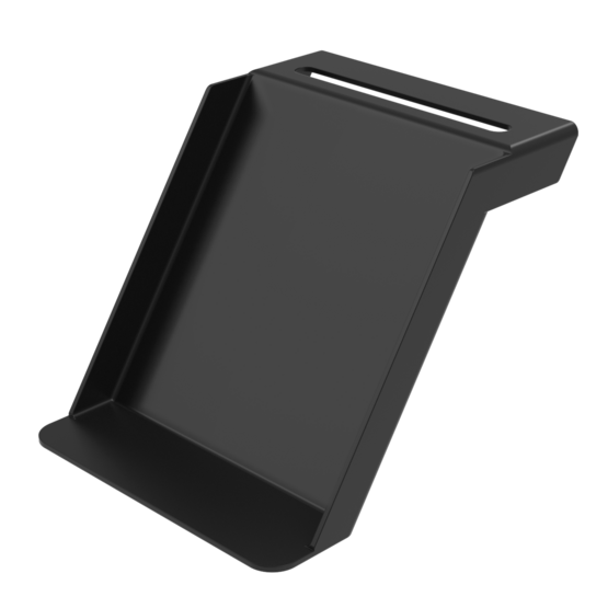
Top Shaft Guards:
These guards are for restricting access to the motor shaft from above the conveyor. They are available in 3 variants:
|
|
|
.png)
.png)
.png)
Due to these intrinsic safety characteristics, O-ring conveyors are categorized as Low-Risk under common industrial safety assessments. The low risk assessment allows for reduced guarding requirements in human-collaborative zones compared to Poly-V systems, which require rigid mechanical shielding.
Assembly Instruction and Installation Procedure
In order to complete a full conveyor section, including legs, follow the instructions below. In order to ease the procedure, a powered 1575mm section of 2 zones will be used as an example.
1) Assemble the legs
Install the Height Adjustment Bracket (MO-CV-030-0007) on all four 45x45mm extrusions (ST-EXT-001-XXXX) using three M8 T-nuts (HW-FN-002-0001) and three M8x16mm (HW-FN-003-0016). Torque them to 15 N.m.
It is suggested to maintain a gap between the bottom of the extrusion and the bottom of the Height adjustment Bracket of approximately 22.5mm. This is done to ensure that the brackets can be adjusted in either direction in the case of a very uneven floor.
Install leg adjustment bracket on extrusions
Assembled leg adjustment bracket
Install the angle adjustment bracket (MO-CV-030-0006__2) on the upper side of the 45x45mm extrusion above using the M8 T-nuts (HW-FN-002-0001 or HW-FN-002-0008), M8x16mm bolts (HW-FN-003-0016) and one M8 washers (HW-WS-001-0001).
Note: Do not fully tighten the M8 screw on the curved slots at this stage.Maintain a gap of approx. 20mm between the top of the extrusion and the inside face of the Angle Adjustment Bracket. This will allow the rotation of the bracket to its desired location. Tighten the M8 screws to 13-15 N.m.
Repeat steps 1 to 3 for all legs of the conveyors. (4 legs per segment)
Install the assembled legs at each extremity of the conveyor c-channel mounting brackets using four M8x16mm screws (HW-FN-003-0016) and nuts (HW-FN-031-0002). Torque them to 13-15 N.m.
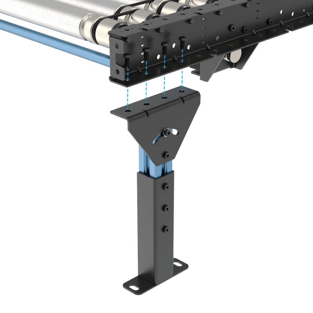
Use a level on the c-channel mounting bracket and on a roller. Adjust the height of each leg on the height adjustment bracket and re-tighten the screws once the level is acceptable. It is normal to have the height of each leg uneven due to the floor having imperfections.
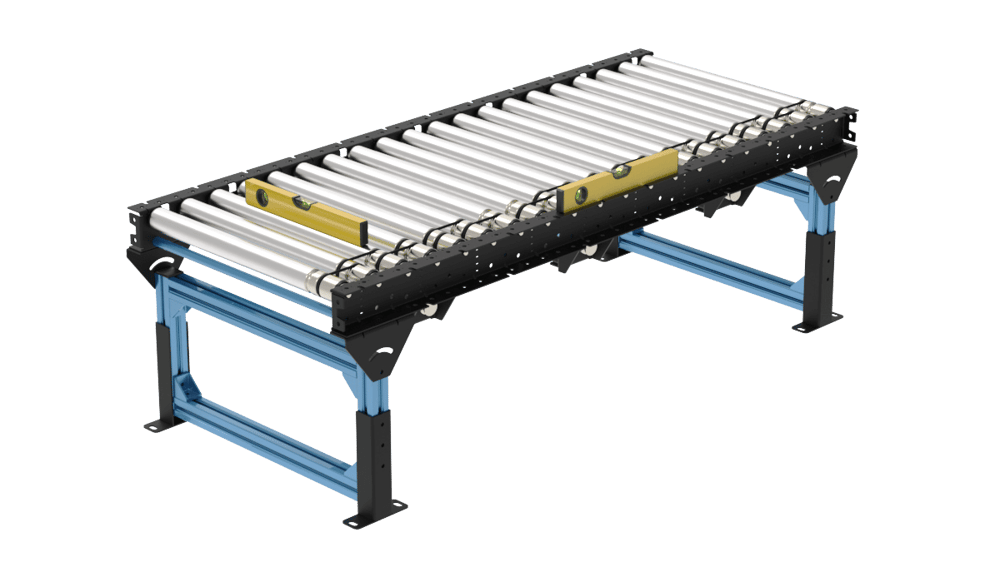
Conveyor leveling
Install one 45x45mm extrusion (ST-EXT-001-0585) with the length of 585mm between each leg using two 45x45 gussets (ST-HP-003-0001 or ST-GP-003-0001).
2) Motor adaptor installation
Place the motor adaptor at the highest position and use four M6x18mm (HW-FN-005-1018) and four M6 washers (HW-WS-005-0001) to attach it to the motor mount of the conveyor.
Note 1: Do not fully tighten them at this stage.
Note 2: When installing the motor adaptor on the motor mount of the conveyor, the two M6 threaded holes on the side of the motor adaptor must be facing down (towards the ground) for tensioning in the next step.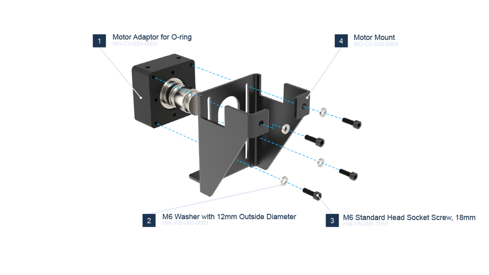
Motor Adaption installation on Motor Mount
Use two M6x70mm (HW-FN-005-1070) and two M6 washers (HW-WS-005-0001) at the location shown below on the Motor Mount (MO-CV-030-0008) and connect the screws to the threaded holes on the bottom of Motor Adaptor (MO-CV-029-0001).
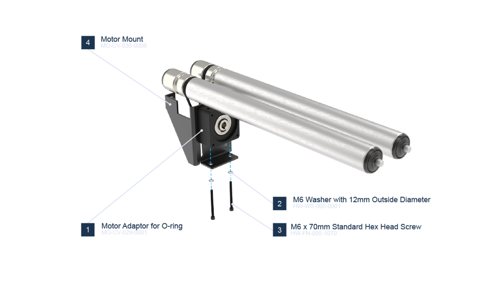
Motor Adaptor installation on rollers
Lower the 2 hanging o-rings (MO-PL-002-0306) onto the grooved shaft of the motor adaptor.
While having the four screws on the Motor Mount (MO-CV-030-0008) slots still loose, use the two M6x70mm (HW-FN-005-1070) screws to bring down the motor adaptor. The motor adaptor will slide down and create tension in the o-rings on the shaft.
When the motor mount is in its final position on the vertical slots, just slightly tighten the two M6x70 mm (HW-FN-005-1070) screws (do not fully tighten). There will be a gap between the bottom of the motor adaptor and the motor mount. Now tighten the four M6x18mm screws (HW-FN-005-1018) to 9 -11 N.m.
3) Floor anchoring
The conveyor must be anchored to the floor. Use four 3/8 x 3” Concrete Screw Anchor (HW-FN-051-2076) for each Height Adjustment Bracket (MO-CV-030-0007).
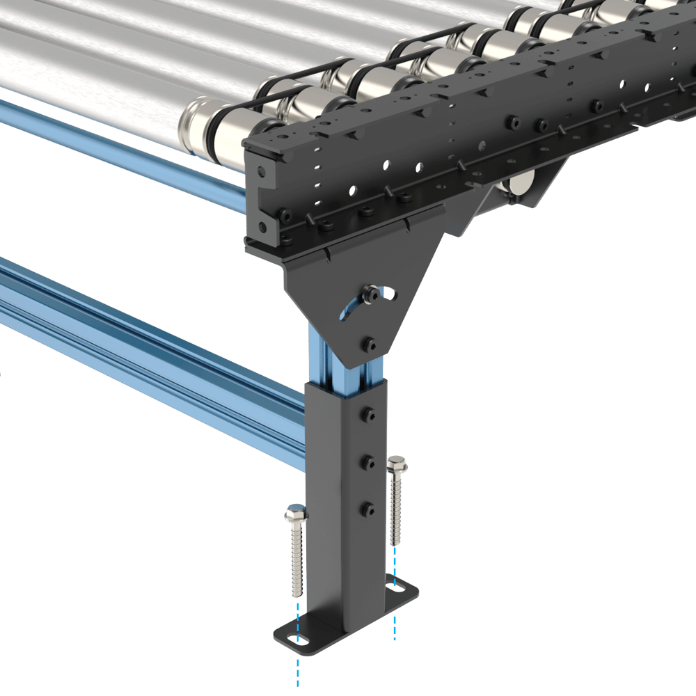
Floor anchoring
4) Sensor installation
If required by the application, install diffuse sensors per design using two M3x18mm (HW-FN-009-0018) which come with the sensor. Torque the M3 screws to 1.2-1.4 N.m.
Note: The location of the sensors is dictated by the application type. In the case of zero accumulation applications, one sensor is needed at the beginning of the conveyor and one sensor at the end of each zone. For installation refer to the Machine Builder design of the application to ensure that the locations of the sensors are correct.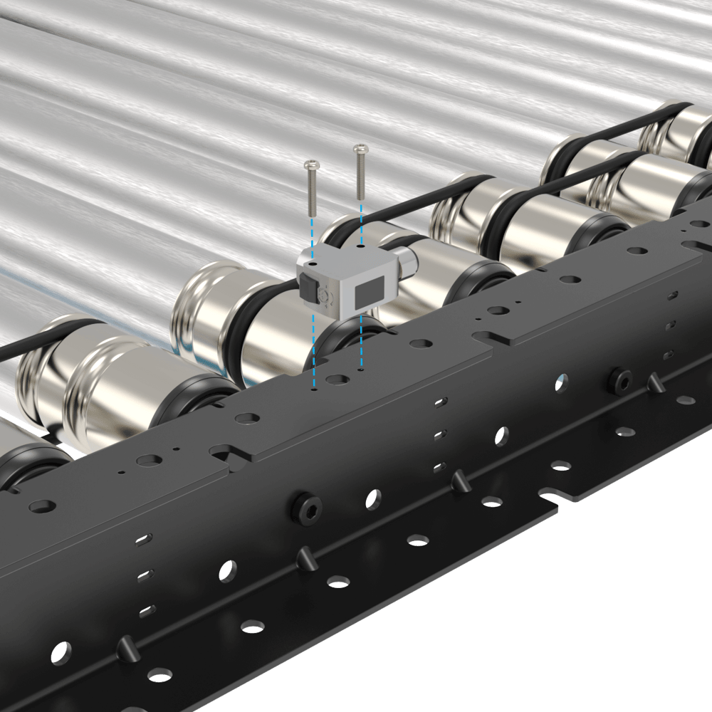
sensor installation
It is possible to installed retro-reflective sensors and all sensors can also be installed using covers to protect them from impacts or bumps. The following images show the installation of a retro reflective sensor kit (CE-SN-007-0011) using the sensor mount (MO-CV-030-0023) and the reflector mount (MO-CV-030-0024).
Retro reflective sensor installed with protective bracket Reflector installed with protective bracket |
|---|
.png)
If you would like to install the sensors in a c-channel used as a guide then a diffuse sensor can be mounted directly in the c-channel like shown in point 1. For retro reflective sensors a special reflector mount is needed for mounting in the c-channel (MO-CV-030-054).
5) Skewed sections cover Brackets
For covering the end gaps of skewed conveyors, a cover bracket and a smaller grooved roller can be installed at both ends of the conveyor. Table below shows the compatible cover bracket part number with each of the skewed conveyors.
Skewed Conveyor Part Number | Width (mm) | Direction | Compatible Cover Bracket Part Number | Associated Small Roller |
|---|---|---|---|---|
405 | Right to Left | MO-CV-001-0135 | ||
Left to Right | ||||
585 | Right to Left | MO-CV-001-0180 | ||
Left to Right | ||||
945 | Right to Left | MO-CV-001-0315 | ||
Left to Right | ||||
Cover Bracket Installation
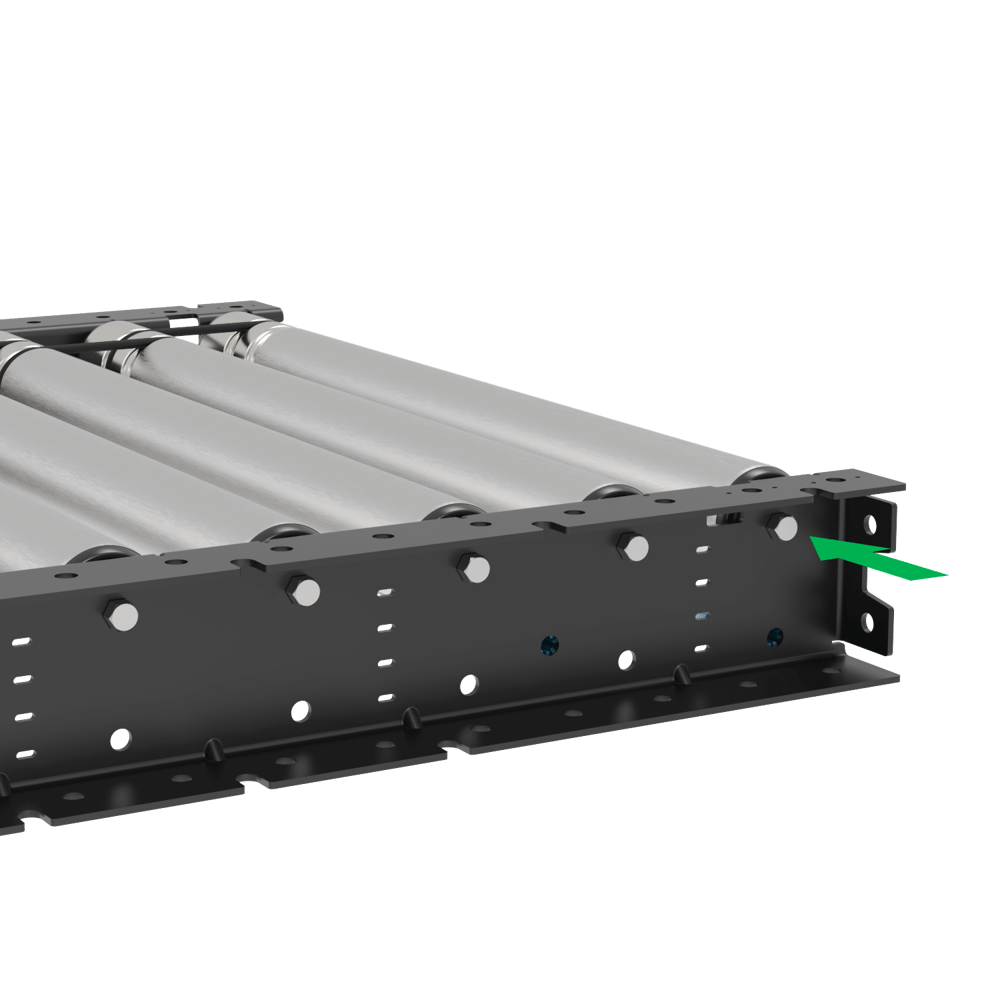
Place the cover bracket between the c-channels of the conveyor, parallel to the rollers, and connect it to the conveyor using the following associated fasteners. Torque the M8 screws to 15-18 N.m.
2x M8x18 mm screws (HW-FN-003-0018)
2x M8 split washers (HW-WS-001-1003)
2x M8 serrated nuts (HW-FN-031-0002)
Skewed bracket installation
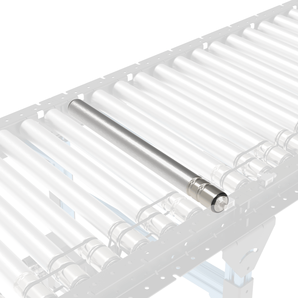
Place the small roller (MO-CV-001-0135/0180/0315) inside the cover into the shown location by inserting in the hex shaft of the small roller into the hex hole of the conveyor and then pressing the other side of the spring-loaded shaft into the hex hole of the cover bracket.
Short roller installation
Note: The installation process is similar to all skewed configurations.
To join two skewed sections, simply add another roller and o-ring set to the BOM. This will allow you to fill the gap with only an additional roller.
 Join two skewed section |
 Additional roller between two skewed sections |
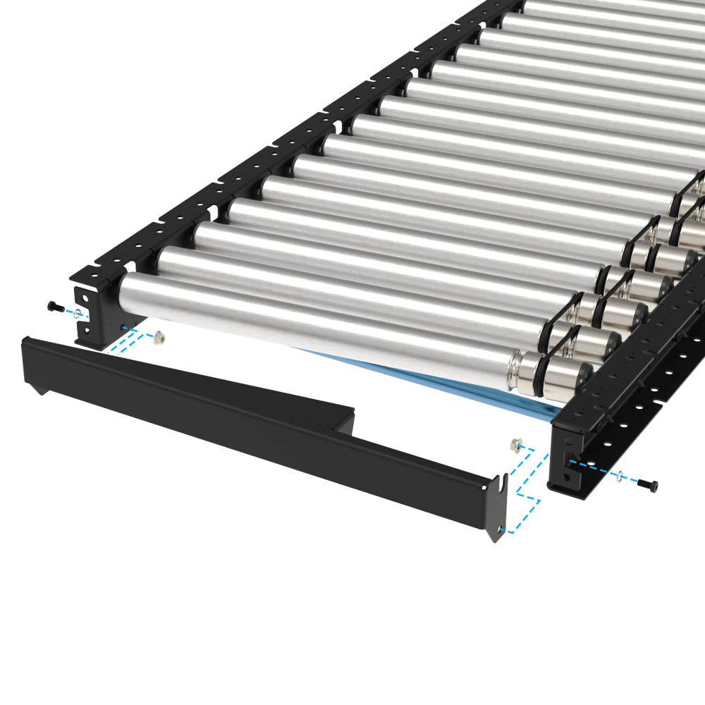
6) Butt-Joining of conveyors
For butt-joining 2 conveyors, only one Angle Adjustment Bracket is required at the joint. Also, the conveyors can be connected to each other using 2 holes at the end of the c-channels. Use the extra associated fasteners coming with the conveyor including M8 serrated nuts (HW-FN-031-0002), M8x18 mm screws (HW-FN-003-0018) and M8 split washers (HW-WS-001-1003) to connect the sections together like the picture below. Torque the M8 screws to 15-18 N.m.
.png) Butt joining of tow conveyors |
7) Motor shaft cover installation
Place the motor shaft cover underneath the conveyor c-channel in front of each motor and use the following associated fasteners for connection. Torque the M8 screws to 15-18 N.m.
2x M8x18 mm screws (HW-FN-003-0018)
2x M8 split washers (HW-WS-001-1003)
2x M8 serrated nuts (HW-FN-031-0002)
|
|
.png)
.png)
Maintenance and Support
1- Maintenance
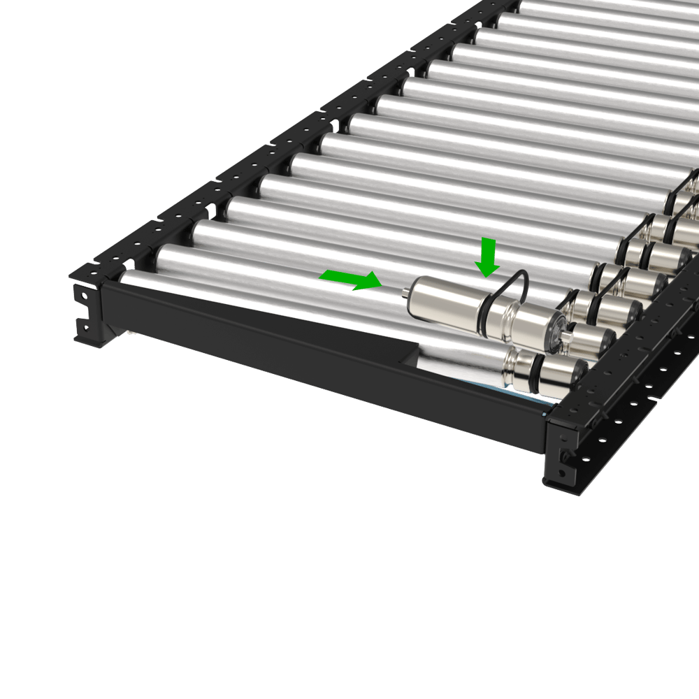
All rollers bearings are sealed and greased for life. In case of failed o-rings, follow these steps:
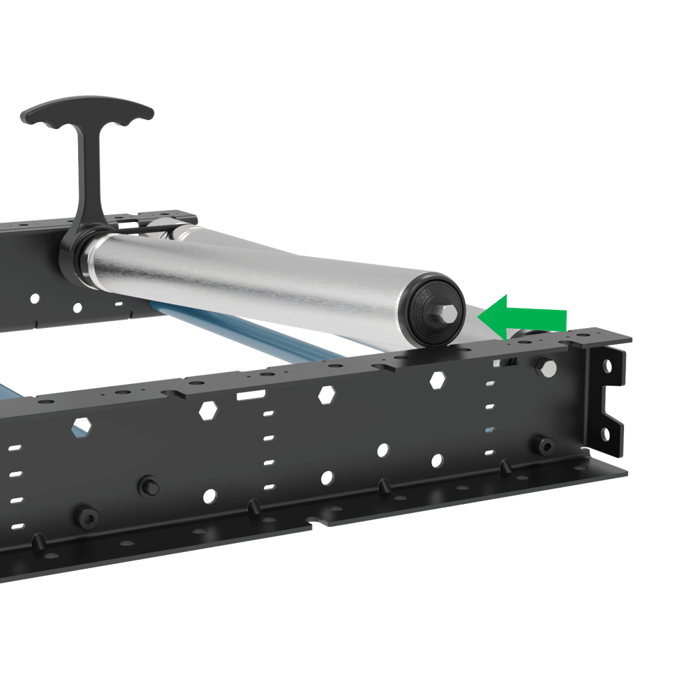
Cut the failed o-ring.
Push in the spring-loaded hex shaft of the non-o-ring side of the 2 rollers.
Removing roller for o-ring replacement
Install the new o-ring on one of the rollers and then use Vention’s O-ring installer tool (HW-TL-004-0003) to stretch the new o-ring to allow enough clearance for the next roller to pass through.
o-ring installation tool usage
Stretching o-ring and reinstall roller
Conveyor Type | O-ring Part Number |
|---|---|
Straight section | |
Curve section | |
Roller to Motor Adaptor (all powered sections) |
2- Support
Should a different configuration than the ones mentioned above be required, reach out to our application specialist team.
Troubleshooting
1- Troubleshooting
The table below lists common issues/errors that may occur during operation of the Smart O-Ring Conveyor system, their possible causes, and recommended corrective actions.
Issue / Error | Possible Causes | Actions |
|---|---|---|
Conveyor does not start / motor does not run |
|
|
Conveyor speed is incorrect or inconsistent |
|
|
Unusual noise during operation (squealing, grinding, or rattling) |
|
|
Sensor not detecting product / false triggers |
|
|
O-ring belts slipping or not driving rollers |
|
|
Boxes not turning correctly on curved sections (45° curve) |
|
|