1. Introduction to State Machines in MachineLogic
The State Machine command in MachineLogic introduces a powerful way to structure and manage complex program flow. Instead of relying solely on sequential commands or intricate conditional logic, you can now design your application as a set of distinct states. Your machine or process transitions between these states based on defined events and conditions, executing specific actions upon entering a new state.
Finite State Machines (FSMs) are a well-established model in computer science and engineering for describing the behavior of systems. They excel at:
Managing Complexity: Breaking down complex processes into understandable and manageable states.
Creating Event-Driven Logic: Naturally handling asynchronous events from sensors, user interfaces, or other systems.
Improving Clarity: Making the program's operational logic more explicit and easier to visualize and understand.
Enhancing Maintainability: Simplifying modifications and debugging by isolating logic within specific states and transitions.
MachineLogic implements state machines visually, allowing you to define states, transitions, and actions through its code-free interface, making this powerful programming paradigm accessible. Figure 1 illustrates a conceptual simple state machine, while Figure 2 shows its equivalent representation within MachineLogic.
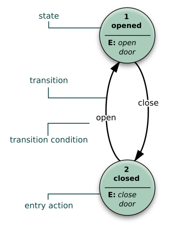
Figure 1: A state diagram for a door that can only be opened and closed
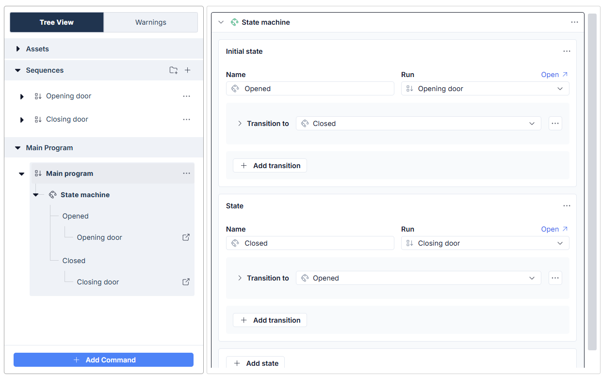
Figure 2: Representation in MachineLogic Code-Free
This guide will delve into the core concepts of FSMs and then provide a detailed exploration of MachineLogic's State Machine command and its functionalities.
2. Core Concepts of Finite State Machines (FSMs)
Before diving into MachineLogic's specific implementation, let's understand some fundamental FSM concepts:
State: A state represents a specific situation, status, or operational mode of your system at a particular point in time. For example, a conveyor might be in an
Idle,RunningForward, orObstructedstate. An FSM has a finite number of such states, and the system can only be in one state at any given moment.Initial State: Every FSM begins in a designated initial state when it starts.
Transition: A transition is the movement from one state to another. Transitions define the allowed pathways through the state machine.
Event (Input): An event is an occurrence that can trigger a transition. This could be a sensor changing state, a message being received, a timer expiring, or a user pressing a button.
Action (Output): An action is an activity or operation performed by the FSM. Actions can be associated with entering a state (Moore machine behavior) or with a transition itself (Mealy machine behavior). MachineLogic primarily associates actions with state entry.
3. MachineLogic State Machine Implementation
Now, let's explore how these concepts are realized within the MachineLogic State Machine command.
3.1. The State Machine Instruction
You add a State Machine to your MachineLogic program like any other instruction. This instruction block then serves as a container for all the states and transition logic that define that particular state machine's behavior. You can have multiple State Machine instructions in your program if needed, for example, to manage different sub-systems independently.
3.2. State (in MachineLogic)
A State in MachineLogic is a fundamental building block representing a distinct status or phase of your machine's operation. As shown in Figure 3, each state you define will have specific properties:
State Name: A unique, user-defined name that identifies the state (e.g., "WaitingForPart", "ProcessingPart", "CycleComplete"). This name is crucial for referencing the state in transitions.
Action (Optional): You can associate an Action with each state, which is executed when the state machine enters this state. MachineLogic uses Sequences to represent Actions
A MachineLogic application can only be in exactly one State within a particular State Machine instance at any given time. Upon entering a state, it executes its defined Action (if any) and then actively monitors its defined "Next State" transitions to determine when and how to move to a subsequent state.
3.3. Action (in MachineLogic)
An Action is a Sequence that the State Machine executes upon entering a given state. This aligns with Moore machine behavior, where outputs (actions) are determined by the current state.
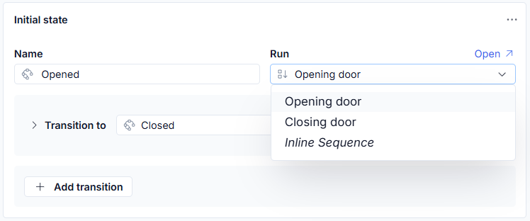
Figure 3 - MachineLogic State and Action (Sequence)
As seen in Figure 3, you can select any of your predefined Sequences from the "Action" dropdown to be associated with a state.
⚠️Important Note:
The State Machine does not block for Actions. If a transition event occurs, the state changes immediately, regardless of whether the current Action Sequence has finished.
Consequently, Actions may continue running in the background after a state change. Ensure you manage or terminate long-running processes (particularly Loops) to avoid logic conflicts in subsequent states.
A state can optionally have no Action defined. In this case, upon entering the state, no specific Sequence is executed, and the State Machine simply waits for a valid transition event.
3.4. Next State (Defining Transitions in MachineLogic)
The Next State list, configured for each state, defines all allowable transitions from the current state to other states. Each entry in this list represents a potential pathway out of the current state.
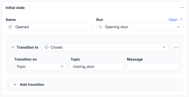
Figure 4: Configuring a state transition on receival of an MQTT Topic
As shown in Figure 4, for each potential "Next State" transition, you must define:
The target "State Name" to transition to.
The Transition Event Type that will trigger the evaluation of this transition.
An optional Condition (guard) that must also be true for the transition to occur.
A single state can have multiple "Next State" entries, allowing it to transition to different states based on different events or conditions. The State Machine evaluates these potential transitions (typically in the order they are listed in the UI) when it is in the current state.
3.5. Transition Event Type (in MachineLogic)
The event that initiates a transition to a Next State can currently take one of two forms:
a) Topic: This type waits for an event to be generated with an exact match to the event topic string defined in the "Topic" field (see Figure 6a). Events can be generated by various means within MachineLogic, such as:
The
Generate Eventcommand.A button widget in the HMI Builder.
Any generic MQTT Topic received on the MachineMotion Controller
b) Digital Input: This type waits for a specific configured Digital Input to reach a defined level (e.g., High/True or Low/False) to trigger the transition (see Figure 5). You select the configured Digital Input and the required state (Level) for the transition.
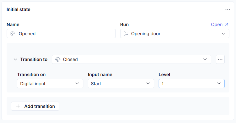
Figure 5: Configuring a transition using a Digital Input signal
3.6. Condition (Guard Condition in MachineLogic)
A Condition, also known as a guard, is an optional Boolean expression that adds another layer of control to a transition. If a transition has a Condition defined, this expression must evaluate to true after the specified Transition Event has occurred for the transition to be allowed. Guard transition can be inserted to a transition using the (…) menu:
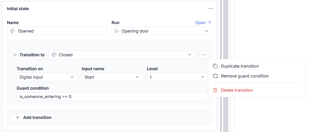
Figure 6: Configuring a state transition on a Digital Input signal with a Guard Condition
As seen in Figure 6, the Condition field can accept a general expression using:
Variables defined in the MachineLogic program.
Arithmetic operators.
Lambda functions (allowing for more complex JavaScript-like expressions).
If a Transition Event occurs but its associated Condition evaluates to false (or is not met), the transition will not occur, and the State Machine will remain in its current state, continuing to monitor for other events or changes that might satisfy this or other defined transitions. If a transition has no Condition defined, it is considered implicitly true once its event occurs.
4. Benefits of Using State Machines in MachineLogic
Leveraging the State Machine command can offer significant advantages:
Structured Logic: Provides a clear and organized way to manage complex sequences of operations and decision points.
Event-Driven Behavior: Ideal for applications that need to react to various asynchronous inputs from sensors, user interfaces, or other systems.
Readability & Maintainability: The visual nature of states and transitions makes the program flow easier to understand, debug, and modify compared to deeply nested conditional statements or complex flag-based logic.
Modularity: Encapsulates specific behaviors and associated actions within individual states, making the overall program more modular.
Reduced Complexity: Simplifies the design of systems with multiple operational modes or intricate error handling and recovery procedures.
5. Examples and Use Cases
5.1 Waiting for multiple possible events
While Figure 1 and 2 show a very simple state machine, the true power of FSMs becomes apparent in more complex scenarios, such as:
Multi-Stage Assembly Processes: Each assembly step (e.g., "LoadPartA", "ClampPartA", "InsertPartB", "StartAssembly") can be a state, with transitions triggered by sensor feedback or completion signals.
Machine Operating Modes: Managing different modes like
Manual_Mode,Automatic_Mode,Setup_Mode,Maintenance_Mode, with specific actions and allowed transitions for each.Complex Pick-and-Place Operations: States for moving to pick, gripping, moving to place, releasing, and returning, with transitions based on sensor inputs and motion completion.
Error Handling and Recovery: Defining
Errorstates that are transitioned to upon fault detection, with actions to log errors, notify operators, or attempt automated recovery sequences.User Interaction Flows: Guiding an operator through a series of steps using an HMI, where each step is a state and HMI button presses trigger transitions.
Initial State Monitoring Multiple Triggers (Wait for Multiple Scenario): Consider an initial state named
WaitingForOperatorInput. This state might have no specific "Action" upon entry but defines multiple "Next State" transitions to handle different operator choices or system events. The following diagram illustrates this concept..png)
Figure 7: State Diagram Representation of example "Wait for Multiple Scenario"
In thisWaitingForOperatorInputstate, the State Machine effectively "waits" for any of these distinct event/condition combinations to occur. The first one to be satisfied will cause the FSM to transition to the corresponding next state and execute its associated action, demonstrating how a single state can act as a branching point based on multiple potential triggers. (Note: The transitions back toWaitingForOperatorInputare illustrative of how a cycle might complete and return to a waiting state. The actual events for these return transitions would be specific to the application.)Looping an Action using Self-Transitions: Imagine you need to repeatedly execute a specific action sequence (e.g., "DispenseMaterial") a certain number of times, or until another condition is met, without using a Loop command within the "DispenseMaterial" sequence itself. You can achieve this using a self-transition. The following diagram illustrates this.
State:
DispensingCycleAction in
DispensingCycle: Execute the "DispenseMaterial" Sequence. This sequence might also increment a variable, saydispenseCount.
Transition 1 (Self-Transition to Loop):
Next State:
DispensingCycle(transitions back to itself)Event Type: Topic
Topic:
CONTINUE_DISPENSING(This event could be generated by the "DispenseMaterial" sequence itself upon its completion, or by a short timer if a pause is needed between dispenses).Condition:
dispenseCount < desiredDispenses(e.g.,dispenseCount < 5)
Transition 2 (Exit Loop):
Next State:
DispensingComplete(or any other next logical state)Event Type: Topic
Topic:
CONTINUE_DISPENSING(same event as above, or a different one likeDISPENSE_COUNT_REACHED)Condition:
dispenseCount >= desiredDispenses
.png)
Figure 8: State Diagram Representation of example "Looping an Action using Self-Transitions"
When the State Machine enters
DispensingCycle, it executes "DispenseMaterial." If theCONTINUE_DISPENSINGevent occurs anddispenseCountis less thandesiredDispenses, it transitions back toDispensingCycle, effectively re-entering the state and re-executing the "DispenseMaterial" action. This continues untildispenseCountmeets the exit condition, at which point Transition 2 is taken. This FSM-level looping can be useful for managing more complex loop conditions or when the action sequence needs to be re-initialized cleanly on each iteration by re-entering the state.
By thoughtfully defining your states, actions, and transitions, you can build robust, responsive, and maintainable automation programs with MachineLogic.