General Frame Maintenance
Vention extrusion frames can be assembled using anti-vibration products such as thread locker, lock washers or wedge locking washers. Regardless of which anti-vibration product is used or if none are used, it is still important to periodically check the tightness of all fasteners in an assembly. Machines that experience large vibrations or have significant safety risks should be checked more frequently. At minimum, we recommend checking fastener tightness in the following intervals:
Upon receipt of your pre-assembled Vention assembly (or upon final assembly).
Both 24 and 48 hours after first commissioning.
Every 3 months for machines exposed to vibrations.
Fasteners should be checked by attempting to tighten a sample set of bolts to 13-15Nm. If the bolts do not maintain the specified torque, it is likely that the effects of vibration are causing them to loosen and a anti-vibration solution should be implemented such as High Strength Threadlocker.
General Lubrication Notes
Proper lubrication minimizes friction, dissipates heat, reduces seal wear, keeps contaminants out, and ensures everything runs smoothly.
For all motion system that requires lubrication, we recommend using a suitable grease with a viscosity grade of NLGI 2. Vention offers a synthetic lubricant in a 14oz tube container (IN-CS-002-0001) and a grease gun kit that comes with all necessary tips and accessories (HW-TL-005-0000) as well as a high pressure grease (HW-CS-002-0003) of the most demanding applications such as the telescopic lift column (MO-LM-050-0830__2).
Prior to doing any maintenance work:
Never perform work on equipment that is energized.
Always follow proper lockout procedures as well as all local safety rules and regulations.
Make sure to use the proper safety equipment at all times.
Linear Bearing Systems
This section covers all of the products offered in the Vention Library under the category of Linear Bearings.
Linear Ball Bearings and Shaft
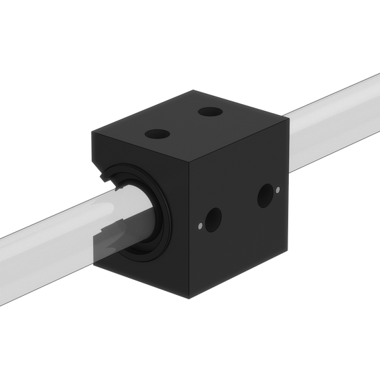 Figure 1: MO-LM-010-0001, Linear Ball Bearing mounted on Linear Guide Shaft MO-LM-014-XXXX |
When to lubricate:
Prior to the initial installation.
Linear bearings and shafts are coated with rust preventive oil for shipping and storage and must be properly lubricated upon unpacking.
Once a year, or after every 100 km of travel—whichever comes first.
The lubrication interval is application-dependent. You may need to lubricate more frequently depending on the duty cycle, usage, and environment. If the lubricant appears to be dispersed before this point or has become dry or crusted, the maintenance interval should be reduced.
Before lubrication:
Visually inspect the shafts and bearing seals for any accumulation of foreign matter.
Using a cloth with solvent, remove any contaminants and old lubricant that may still be in place on the shaft and linear bearing seals.
Cycle the linear bearing along the shaft several times. Wipe with a dry, lint-less cloth and perform the lubrication immediately after.
Lubrication Procedure:
All linear bearings come with standard straight grease fitting on one side (as shown below). We recommend injecting the grease through the grease fitting using a grease gun equipped with a standard grease fitting dispensing tip.
In order to distribute the grease throughout the linear bearing elements, it is recommended that the bearing be run two to five times over its complete operating stroke.
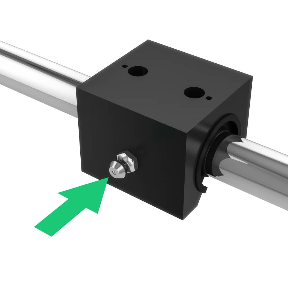
Figure 2: Green arrow indicates the Zerk fitting used for lubricating the bearings.
For light-duty applications in clean environments only: If the grease fitting is not accessible or not present (older design), you can apply the lubricant directly on the shaft using a clean cloth. Ensure that 100% of the shaft surface is covered with a thin layer of lubricant, then cycle the bearing along the shaft several times to ensure proper application and distribution. Do not leave a heavy film of lubricant on the shaft. Keep the shaft barely damp with lubricant.
Plain Bearings and and Shaft
 Figure 3: MO-LM-010-0010, Linear Plain Bearing mounted on Linear Guide Shaft MO-LM-014-XXXX. |
When to lubricate:
Plain bearings are characterized as maintenance-free. The bearing provides its own lubrication throughout the system’s lifetime without any need for maintenance. Self-lubrication happens during the ongoing process in which the bearing liner transfers to the shaft, during which a thin film is deposited on the shaft surface that fills in any valleys in the surface finish.
Lubrication is optional with plain bearings. If desired, apply one of the recommended lubricants (listed below) directly on the shaft using a clean cloth. Cover all the visible shaft surface with a thin layer of lubricant, then cycle the bearing along the shaft several times to ensure proper application and distribution.
Lubricating plain bearings enhance performances by:
Reducing friction.
Minimizing wear.
Allowing for greater speed.
Recommended lubricants:
Waylube oil.
Petroleum-based grease.
3-in-1 oils.
Not recommended (avoid):
WD-40.
PTFE sprays.
Fluorocarbons.
Silicone-based lubricants.
Break-in period:
To create the initial self-lubrication conditions, plain bearings require a break-in period of around 50 to 100 full strokes of continuous operation. To maximize the operating life cycle on plain bearings, clean the shaft with 3-in-1 oil before installing the plain bearing. This ensures the shaft surface will receive a full transfer of bearing material.
After the break-in period, shaft cleaning increases the wear of the bearing. This is due to the transfer process being performed over and over again. If the shaft needs to be cleaned, do not use alcohol or alcohol-based cleaners, which will remove all the previously transferred material.
Enclosed Linear Profile Guide
 Figure 8: MO-LM-028-XXXX, Enclosed Linear Profile Guide. |
When to lubricate (Bearing):
The guide comes completely pre-lubricated. The maintenance must be performed at the first maintenance interval.
Once a year, or after every 100 km of travel—whichever comes first.
The lubrication interval is application-dependent. You may need to lubricate more frequently depending on the duty cycle, usage, and environment. If the lubricant appears to be dispersed before this point or has become dry or crusted, the maintenance interval should be reduced.
Before lubrication:
Remove the grease port cover.
Manually move the gantry to the end of travel so that the grease fitting is visible through the grease port.
Lubrication Procedure:
Connect the grease gun to the grease fitting using the 90 degree push on grease fitting.
Pump the grease gun until 7ml of the grease has been injected (approximately 20 pumps of our grease gun).
Manually jog the machine to the other end of travel and repeat the previous steps on the opposite bearing grease fitting.
The total amount of grease injected should be 14ml of NLGI 2 grease.
If lubricating MO-LM-041-XXXX, this process must be done for both bearings on either end of the gantry system.
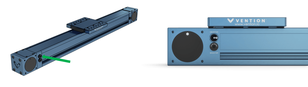 Figure 9: Green arrow points to one of the possible grease ports. Remove the port and bring the gantry to end-of-travel to expose the Zerk fitting. |
When to lubricate (Cover Strip):
The actuator comes completely pre-lubricated. The maintenance must be performed at the first maintenance interval or if any dryness is present on the strip.
Once every other month, or after every 50 km of travel—whichever comes first.
The lubrication interval is application-dependent. You may need to lubricate more frequently depending on the duty cycle, usage, and environment. If the lubricant appears to be dispersed before this point or has become dry or crusted, the maintenance interval should be reduced.
Before lubrication:
Clean the cover strip using isopropyl alcohol.
Inspect the strip for any damage. If damage is present contact us for the appropriate replacement parts and procedure.
Lubrication Procedure:
After cleaning and inspecting the cover strip lubricate it by adding grease to the cover strip surface.
Manually move the gantry back and forth, ensuring that a light layer of grease is distributed across the cover strip.
Wipe off excess grease.
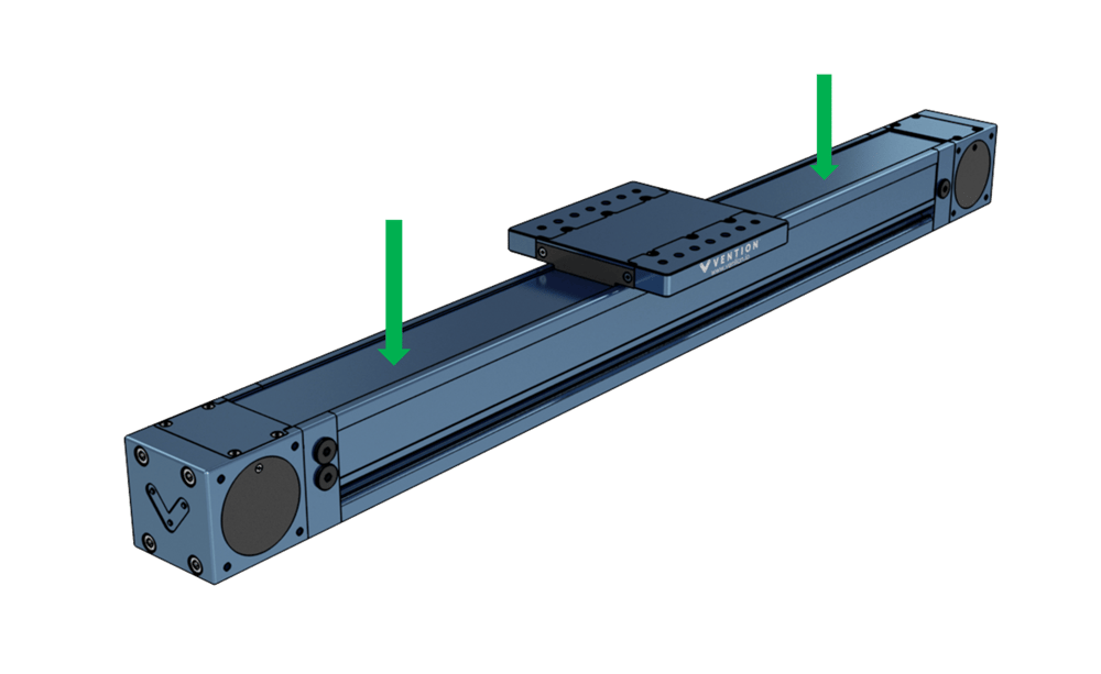
Figure 10: Green arrows point to suggested locations for application of grease to the cover strip.
20mm Series Profile Guide Bearings
.png) Figure 1: MO-LM-010-0001, Linear Ball Bearing mounted on Linear Guide Shaft MO-LM-014-XXXX |
When to lubricate:
Upon initial installation.
Linear bearings and shafts are vacuum sealed with rust preventive oil from the manufacturer and must be properly lubricated with grease before use.
Once a year, or after every 100 km of travel—whichever comes first.
The lubrication interval is application-dependent. You may need to lubricate more frequently depending on the duty cycle, usage, and environment. If the lubricant appears to be dispersed before this point or has become dry or crusted, the maintenance interval should be reduced.
Before lubrication:
Visually inspect the shafts and bearing seals for any accumulation of foreign matter.
Using a cloth with solvent, remove any contaminants and old lubricant that may still be in place on the shaft and linear bearing seals.
Cycle the linear bearing along the shaft several times. Wipe with a dry, lint-less cloth and perform the lubrication immediately after.
Lubrication Procedure:
All linear bearings come with optional grease fitting. The grease port is plugged with a M3 set screw which can be removed with a 1.5mm allen key. Grease can be injected using a needle nozzle directly into the port or the included zerk fittings can be installed. Note that the zerks included are not standard size but will work with push style grease gun like the standard Vention grease gun.
In order to distribute the grease throughout the linear bearing elements, it is recommended that the bearing be run two to five times over its complete operating stroke.
.png)
Figure 2: Green arrow indicates the grease port used for lubricating the bearings.
Linear Motion
This section covers all of the products offered in the Vention Library under the category of Linear Motion with the exception of the Linear Bearings covered in the section above.
Ball Screw Assembly
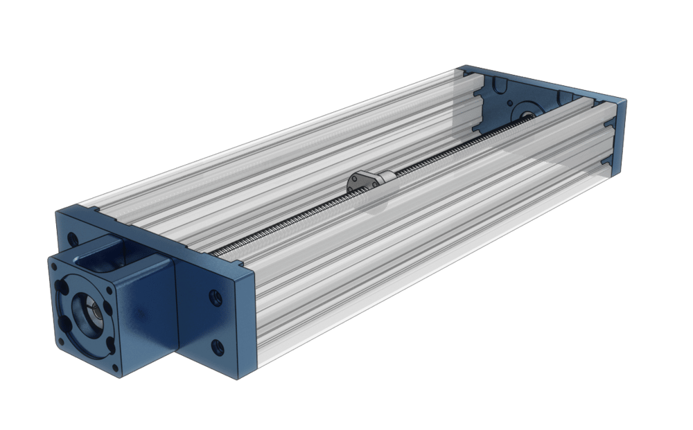 Figure 4: MO-LM-003-XXXX, Ball Screw Actuator. |
When to lubricate:
Prior to the initial installation.
The screw shaft and ball nut are coated with rust preventive oil for shipping and storage and must be properly lubricated upon assembly.
Once every 6 months, or after every 500,000 revolutions —whichever comes first.
The lubrication interval is application-dependent. You may need to lubricate more frequently depending on the duty cycle, usage, and environment. If the lubricant appears to be dispersed before this point or has become dry or crusted, the maintenance interval should be reduced.
Before lubrication:
Visually inspect the screw shaft and ball nut for any accumulation of foreign matter.
Using a cloth with solvent, remove any contaminants and old lubricant that may still be in place on the screw shaft and ball nut.
Cycle the ball nut along the screw shaft several times. Wipe with a dry, lint-less cloth and perform the lubrication immediately after.
Lubrication Procedure:
The ball nut comes with standard straight grease fitting (as shown below). We recommend injecting the grease through the grease fitting using a grease gun equipped with a standard grease fitting dispensing tip. The ball nut can be filled completely with grease.
In order to distribute the grease throughout the ball screw elements, it is recommended that the ball nut be run two to five times over its complete operating stroke.
Never, under no circumstance, remove the ball but from the screw shaft.
Never, under any circumstance, remove the ball but from the screw shaft.
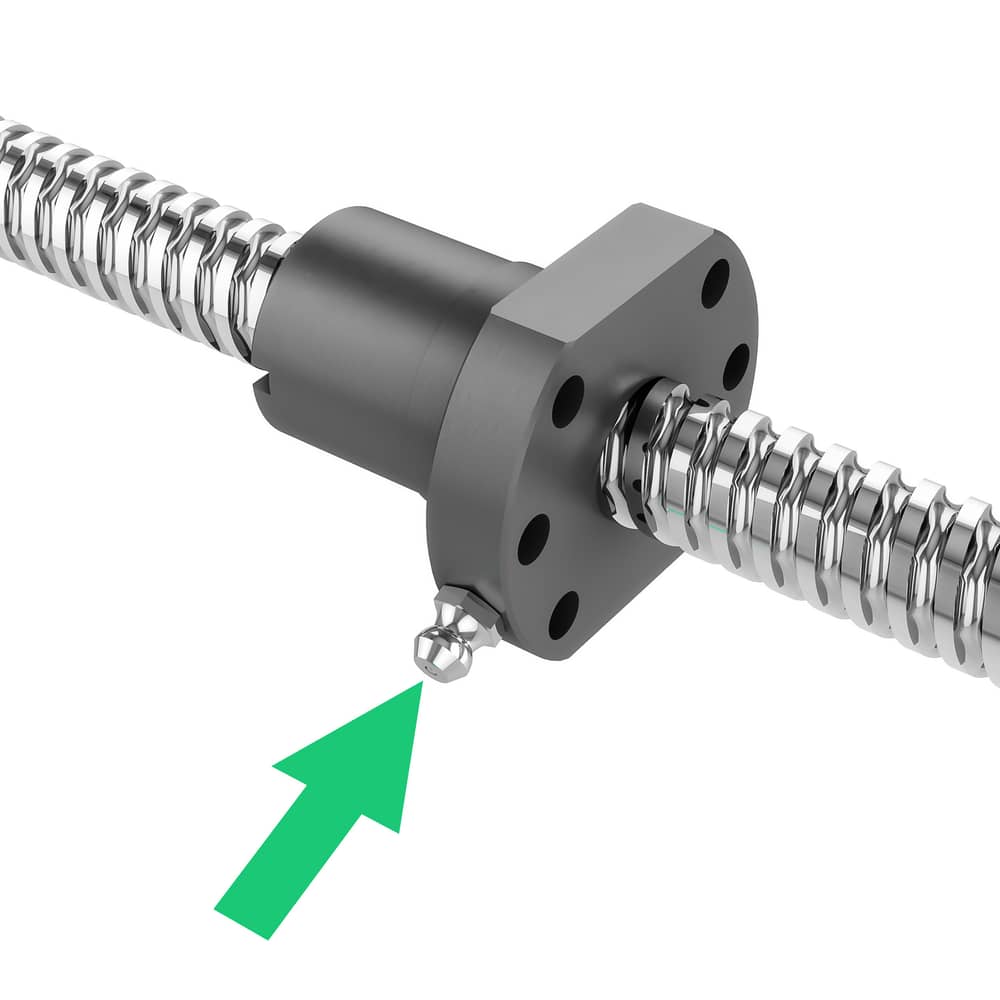 Figure 5: Green arrow indicates the Zerk fitting used for lubricating the ball nut. |
Rack and Pinion Assembly and Gear Rack Segment
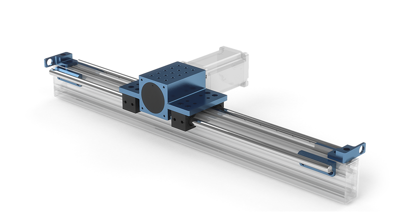 Figure 6: MO-LM-019-0001 and MO-LM-020-XXXX, Rack and Pinion Actuator. |
When to lubricate:
Prior to the initial installation.
The pinion and gear segments are coated with rust preventive oil for shipping and storage and must be properly lubricated upon assembly.
Once every 6 months, or after every 20 km of travel —whichever comes first.
The lubrication interval is application-dependent. You may need to lubricate more frequently depending on the duty cycle, usage, and environment. If the lubricant appears to be dispersed before this point or has become dry or crusted, the maintenance interval should be reduced.
Before lubrication:
Visually inspect the gear rack segments for any accumulation of foreign matter.
Using a cloth with solvent, remove any contaminants and old lubricant that may still be in place on the gear rack segments.
Cycle the pinion housing along the gear rack segments several times. Wipe with a dry, lint-less cloth and perform the lubrication immediately after.
Lubrication Procedure:
We recommend applying the grease directly on the gear rack segments (as shown below) so that each tooth flank is barely damp with lubricant.
In order to distribute the grease throughout the gear rack segments and on the pinion, it is recommended to run the pinion housing two to five times over its complete operating stroke.
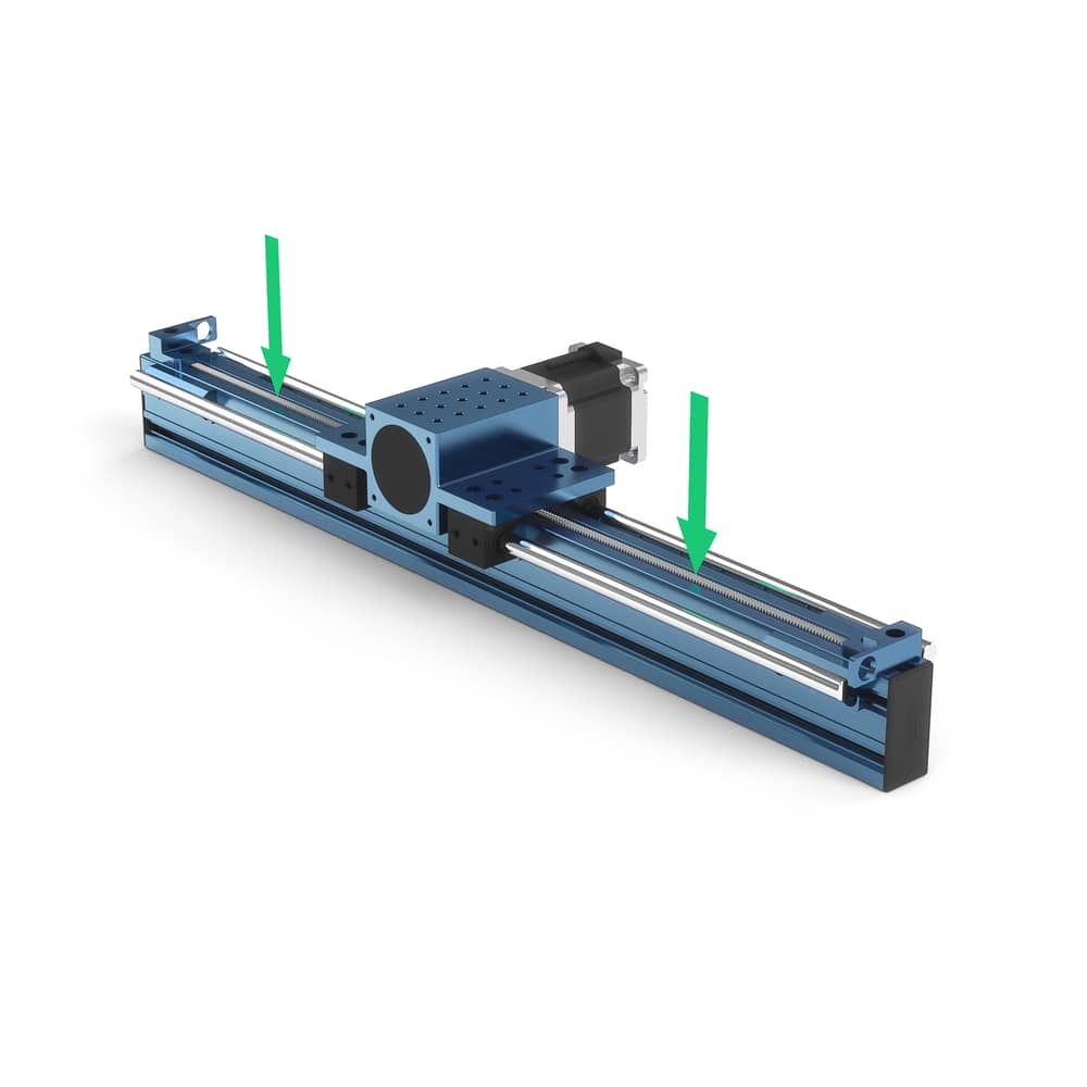
Figure 7: Green arrows indicate suggested locations for applying grease to the gear rack, MO-LM-020-XXXX.
Enclosed Timing Belt Actuator
.png) Figure 8: MO-LM-026-XXXX, Enclosed Timing Belt Actuator. |
When to lubricate (Bearing):
The actuator comes completely pre-lubricated. The maintenance must be performed at the first maintenance interval.
Once a year, or after every 100 km of travel—whichever comes first.
The lubrication interval is application-dependent. You may need to lubricate more frequently depending on the duty cycle, usage, and environment. If the lubricant appears to be dispersed before this point or has become dry or crusted, the maintenance interval should be reduced.
Before lubrication:
Remove the grease port cover.
Manually move the gantry to the end of travel so that the grease fitting is visible through the grease port.
Lubrication Procedure:
Connect the grease gun to the grease fitting using the 90 degree push on grease fitting.
Pump the grease gun until 7ml of the grease has been injected (approximately 20 pumps of our grease gun).
Manually jog the machine to the other end of travel and repeat the previous steps on the opposite bearing grease fitting.
The total amount of grease injected should be 14ml of NLGI 2 grease.
If lubricating MO-LM-027-XXXX, MO-LM-040-XXXX, or MO-LM-041-XXXX, this process must be done for both bearings on either end of the gantry system.
Figure 9: Green arrow points to one of the possible grease ports. Remove the port and bring the gantry to end-of-travel to expose the Zerk fitting. |
When to lubricate (Cover Strip):
The actuator comes completely pre-lubricated. The maintenance must be performed at the first maintenance interval or if any dryness is present on the strip.
Once every other month, or after every 50 km of travel—whichever comes first.
The lubrication interval is application-dependent. You may need to lubricate more frequently depending on the duty cycle, usage, and environment. If the lubricant appears to be dispersed before this point or has become dry or crusted, the maintenance interval should be reduced.
Before lubrication:
Clean the cover strip using isopropyl alcohol.
Inspect the strip for any damage. If damage is present contact us for the appropriate replacement parts and procedure.
Lubrication Procedure:
After cleaning and inspecting the cover strip lubricate it by adding grease to the cover strip surface.
Manually move the gantry back and forth, ensuring that a light layer of grease is distributed across the cover strip.
Wipe off excess grease.
Figure 10: Green arrows point to suggested locations for application of grease to the cover strip.
Enclosed Ball Screw Actuator & Enclosed Lead Screw Actuator
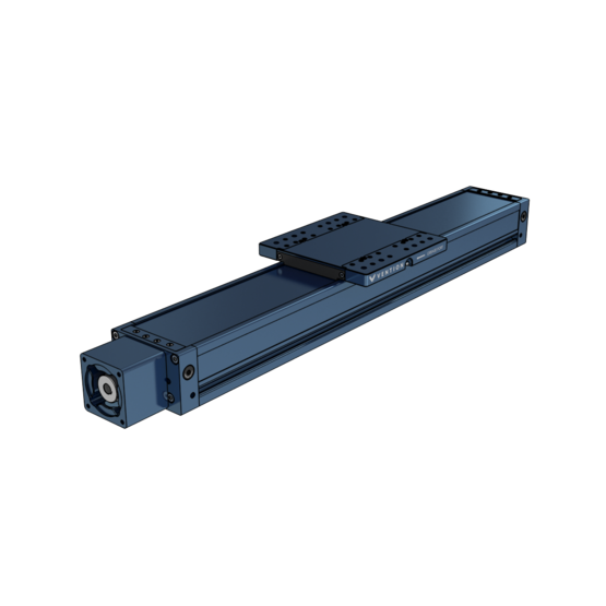 Figure 11: MO-LM-039-XXXX, Enclosed Ball Screw Actuator. |
When to lubricate (Bearing):
The actuator comes completely pre-lubricated. The maintenance must be performed at the first maintenance interval.
Once a year, or after every 100 km of travel for the ball screw or 50 km for the lead screw—whichever comes first.
The lubrication interval is application-dependent. You may need to lubricate more frequently depending on the duty cycle, usage, and environment. If the lubricant appears to be dispersed before this point or has become dry or crusted, the maintenance interval should be reduced.
Before lubrication:
Clean the cover strip using isopropyl alcohol.
Inspect the strip for any damage. If damage is present contact us for the appropriate replacement parts and procedure.
Lubrication Procedure:
After cleaning and inspecting the actuator, connect a standard grease gun to one of the zerk fittings on the gantry plate. Either fitting can be used.
The total amount of grease injected should be 18ml of NLGI 2 to completely flush the system.
Jog the actuator from home to end of travel a few times to verify operation is smooth and free of any unexpected noise.
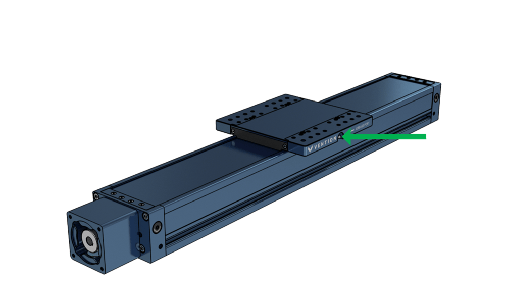
Figure 12: Green arrow points to Zerk fitting located on the gantry. There are fittings on both sides of the gantry.
Note: if you are experiences issues with noise, consider to switching to the extreme pressure grease offered in the consumables section of the part library. This grease is better for high temp and high pressure applications and will keep the lead screw operating smoothly and quietly at higher duty cycles.
Telescopic Lift Column
Note : We recommend using the extreme pressure grease offered in the consumables section of the part library for this actuator. This grease is better for high temp and high pressure applications and will keep the lift column operating smoothly and quietly for longer.
The internal greasing system to service both screws is accessible through a grease port when the actuator is at its home position.
|
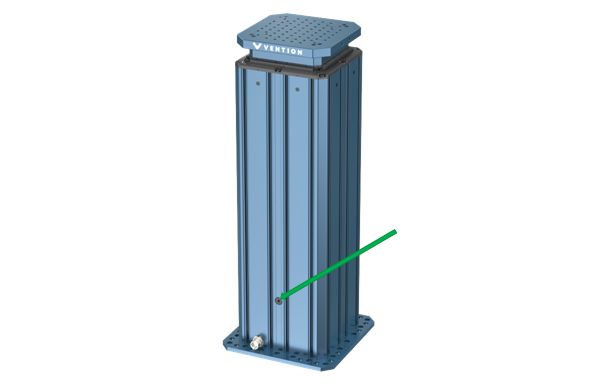
To access the zerk fitting, ensure the actuator is at the home position then unscrew to cover with a 5mm hex key. Once removed the zerk fitting will be accessible:
|
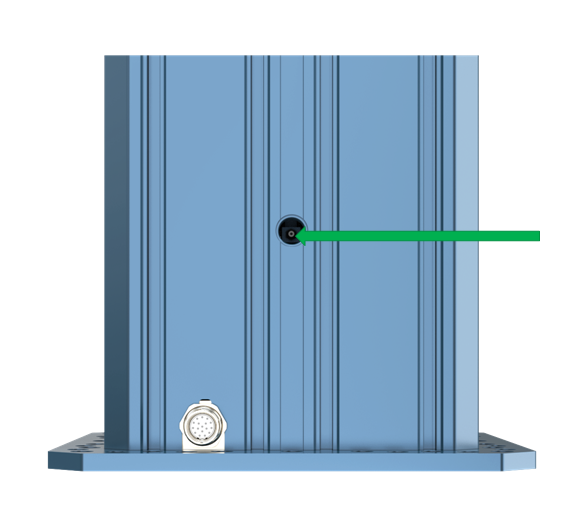
During break in period, the system may require more frequent greasing, after every few thousand cycles. After the break in period is complete, the greasing interval can be increased. If your Telescopic Lift is making any vibration noises or is operating slower than usual it must be greased to bring performance back into specifications.
Rotary Motion
This section covers all of the products offered in the Vention Library under the category of Rotary Motion.
Rotary Actuator Assembly
 Figure 13: MO-RM-002-0001, Rotary Actuator. |
When to lubricate:
Prior to the initial installation.
The rotary actuator driving elements are coated with rust preventive oil for shipping and storage. The pinion gear teeth and the slewing bearing rolling elements and gear teeth must be properly lubricated upon assembly.
Once every 6 months, or after every 10,000 revolutions —whichever comes first.
The lubrication interval is application-dependent. You may need to lubricate more frequently depending on the duty cycle, usage, and environment. If the lubricant appears to be dispersed before this point or has become dry or crusted, the maintenance interval should be reduced.
Before lubrication - Gear elements only:
Remove the motor or the top plate to have clear access to the gear elements.
Visually inspect the slewing bearing and pinion gear teeth for any accumulation of foreign matter.
Using a cloth with solvent, remove any contaminants and old lubricant that may still be on the pinion and slewing bearing gear teeth.
Wipe with a dry, lint-less cloth and perform the lubrication immediately after.
Lubrication Procedure - Rolling elements:
The slewing bearing rolling elements must be greased using the standard elbow grease fitting (as shown below). We recommend injecting the grease through the grease fitting using a grease gun equipped with a standard grease fitting dispensing tip.
In order to distribute the grease throughout the rolling elements, it is recommended to manually turn the slewing bearing two to five full rotations in both directions.
Figure 14: Green arrow points to the Zerk fitting used to lubricate the Rotary Actuator bearing.
Lubrication Procedure - Gear elements:
We recommend applying the grease directly on the pinion and slewing ring gear teeth (as shown below) so that each tooth flank is barely damp with lubricant.
In order to distribute the grease throughout the pinion and slewing ring gear, it is recommended to install the motor and run the rotary actuator two to five full rotations in both directions.
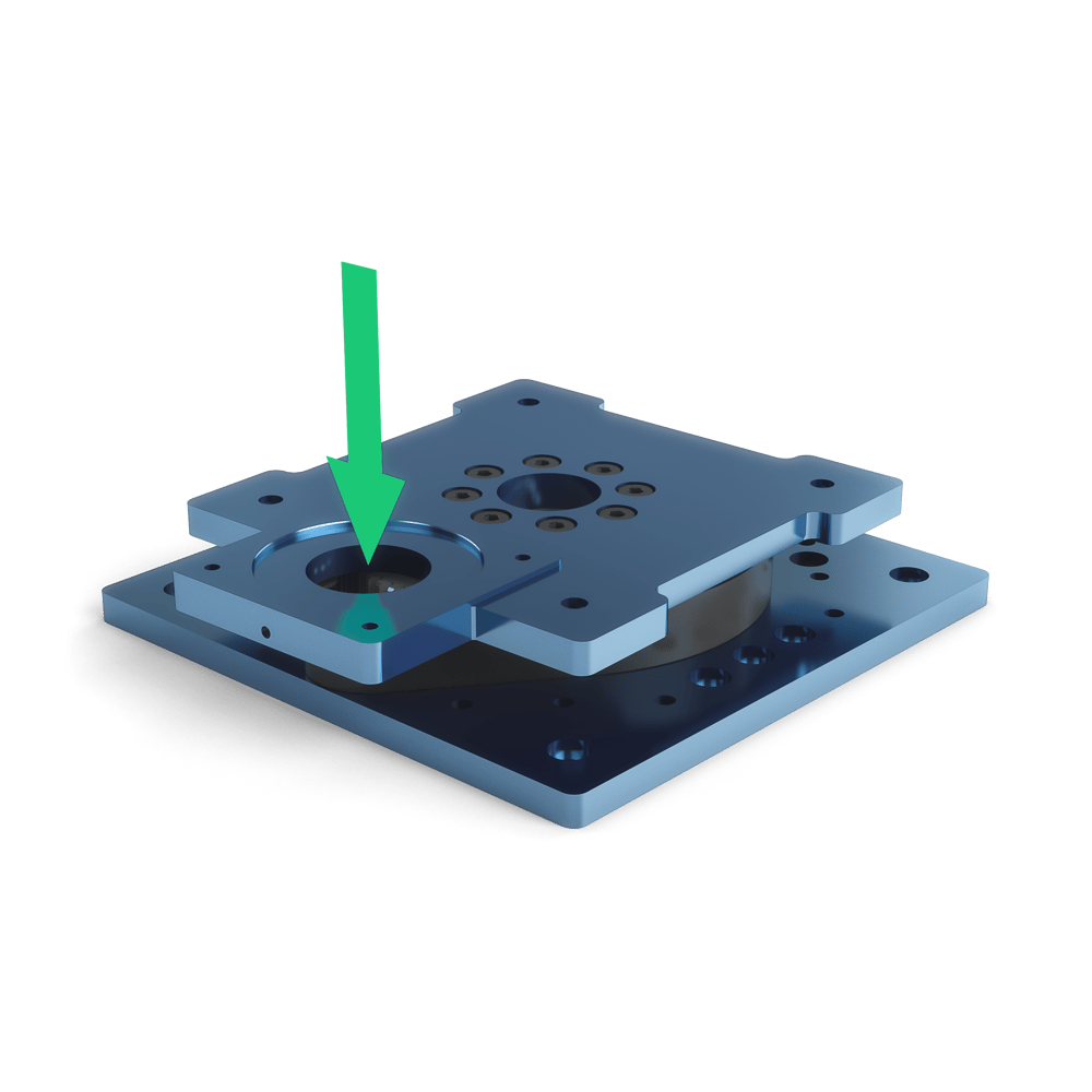
Figure 15: Green arrow shows where grease can be added to lubricate the gear teeth.
Rotary Actuator Version 2
 Figure 16: MO-RM-002-0001__2, Rotary Actuator version 2. |
Note: The second revision of the rotary actuator has an enclosed planetary gearbox. It arrives pre-lubricated and does not require any additional lubrication.
Turn Table
 Figure 17: MO-RM-003-0001, Turn Table. |
When to lubricate:
Once every 6 months, or after every 10,000 revolutions —whichever comes first.
The lubrication interval is application-dependent. You may need to lubricate more frequently depending on the duty cycle, usage, and environment. If the lubricant appears to be dispersed before this point or has become dry or crusted, the maintenance interval should be reduced.
Before lubrication - Gear elements only:
Visually inspect the slewing bearing for any accumulation of foreign matter.
Using a cloth with solvent, remove any contaminants and old lubricant that may still be on the slewing bearing.
Wipe with a dry, lint-less cloth and perform the lubrication immediately after.
Lubrication Procedure - Rolling elements:
The slewing bearing rolling elements must be greased using the standard grease fitting (as shown below). We recommend injecting the grease through the grease fitting using a grease gun equipped with a standard grease fitting dispensing tip.
In order to distribute the grease throughout the rolling elements, it is recommended to manually turn the slewing bearing two to five full rotations in both directions.
This slewing bearing has two grease fittings, grease only needs to be applied to one of them to fully grease the system. Use whichever is convenient.
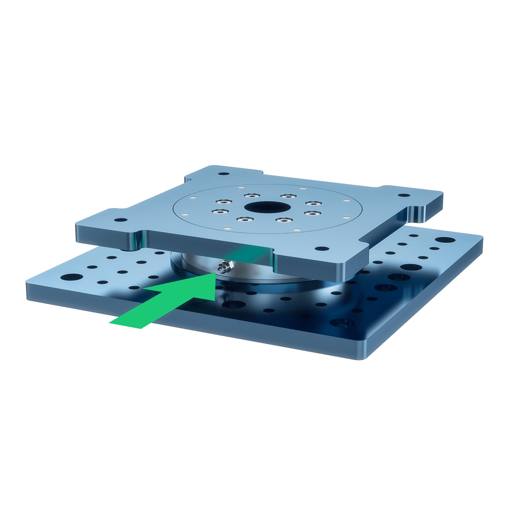
Figure 18: Green arrow points to the Zerk fitting that lubricates the Turn Table's bearings.