Overview
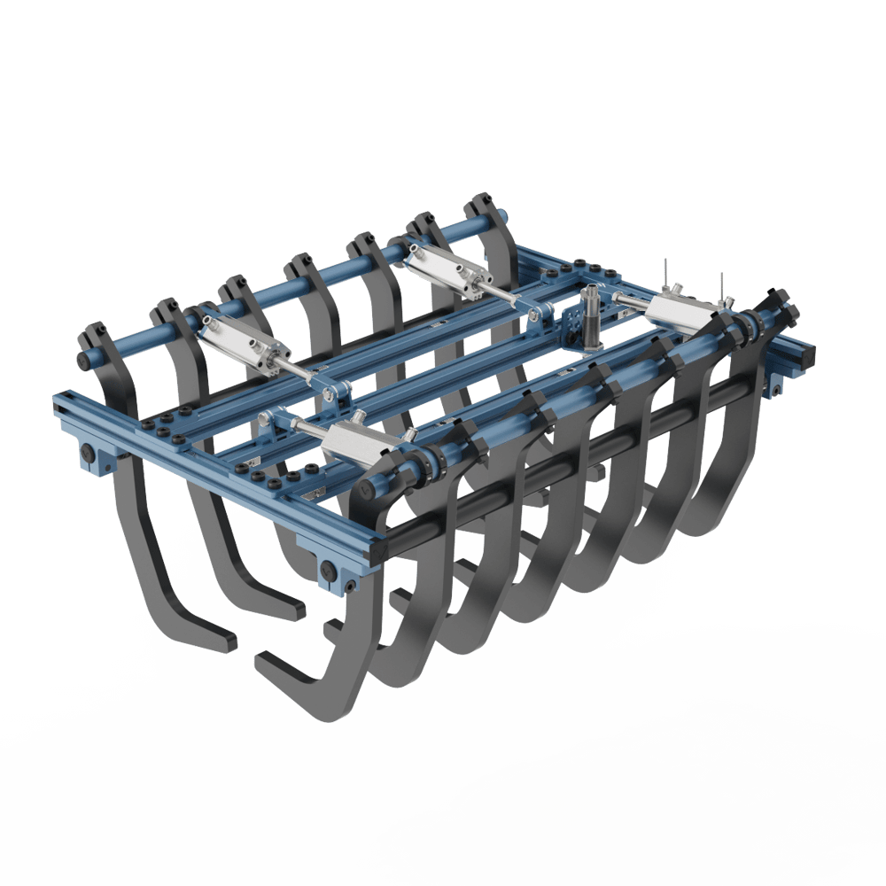
The bag gripper is a versatile, pneumatically actuated mechanical gripper. Designed for applications involving bags, like palletizing, this gripper can handle materials that are unreliable or impossible to grasp using suction. Its strength-to-weight ratio offers an excellent alternative to conventional vacuum and suction-cup grippers.
|
Applications
The bag gripper is ideal for cartesian palletizing applications. Add it to the end of a cartesian palletizer’s z-axis to pick and palletize bags from roller conveyors, for an automated production line.
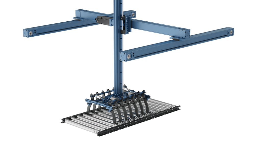 3-Axis Cartesian System with Bag Gripper (on z-axis) |
Explore public designs to get an idea and see examples of palletizers with roller conveyor infeeds.
Tech specs
Gripper weight | 7.6 kg |
Max bag weight | 35 kg |
Recommended operating pressure | 0.55 MPa |
Bag length | 250 – 550 mm |
Bag width* | 80 – 225 mm |
Bag height | 40 – 130 mm |
Finger pitch | 90 mm |
Compatible picking surfaces | |
Included sensors |
*Refers to bag width after settling, if there is vibration.
Note: Bag dimension ranges are valid for stiff plastic bags (3–4 mm thick) with dense/tightly packed contents. If you have questions about the feasibility of a particular bag, please contact our Application Engineering department.
Compatible mounting hardware
This gripper has two mounting options:
Rotary Actuator V2 with Sensor Provision (MO-RM-002-0001__3). Best for when gripper rotation is required.
Actuator Mounting Plate (ST-GP-005-0010). Best for when gripper rotation is not required.
To mount either option to the gripper, use the four included fasteners (HW-FN-003-0012) at each corner of the gripper.
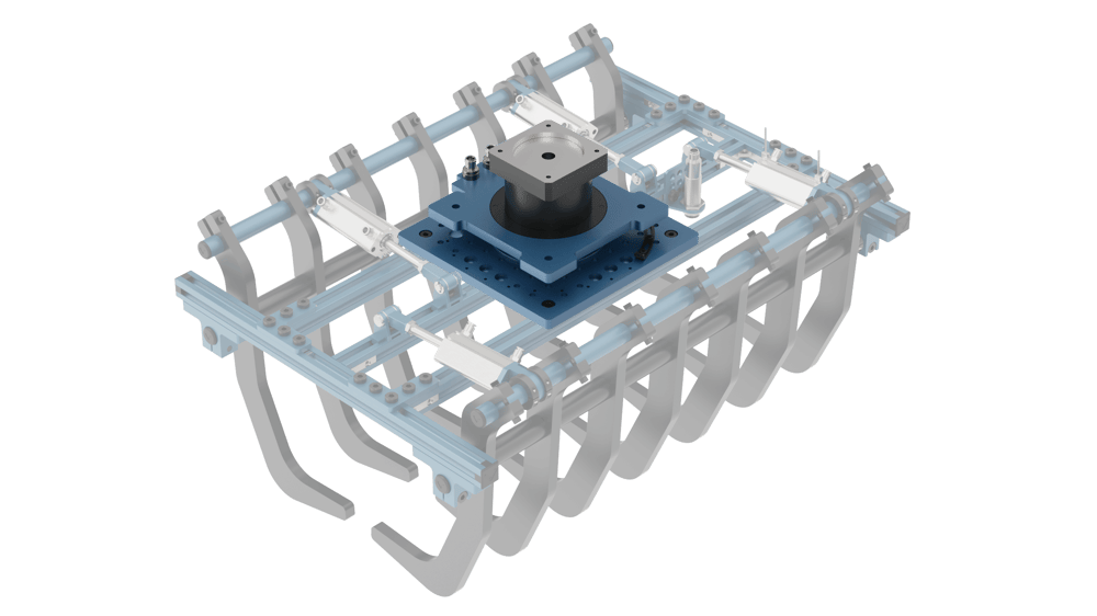 Bag Gripper with Rotary Actuator | 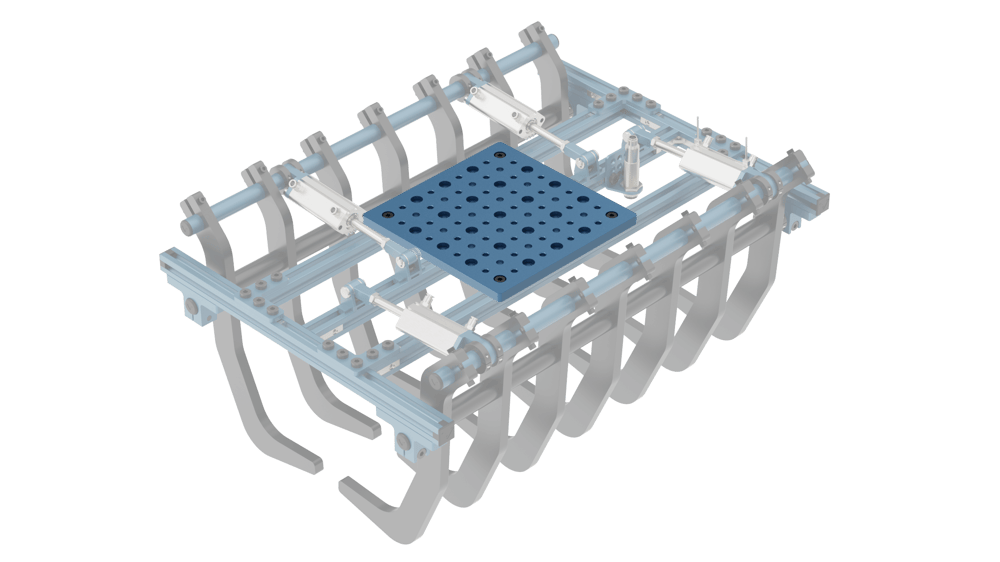 Bag Gripper with Actuator Mounting Plate |
Getting started
Gripper setup
Unfold the two rows of fingers.
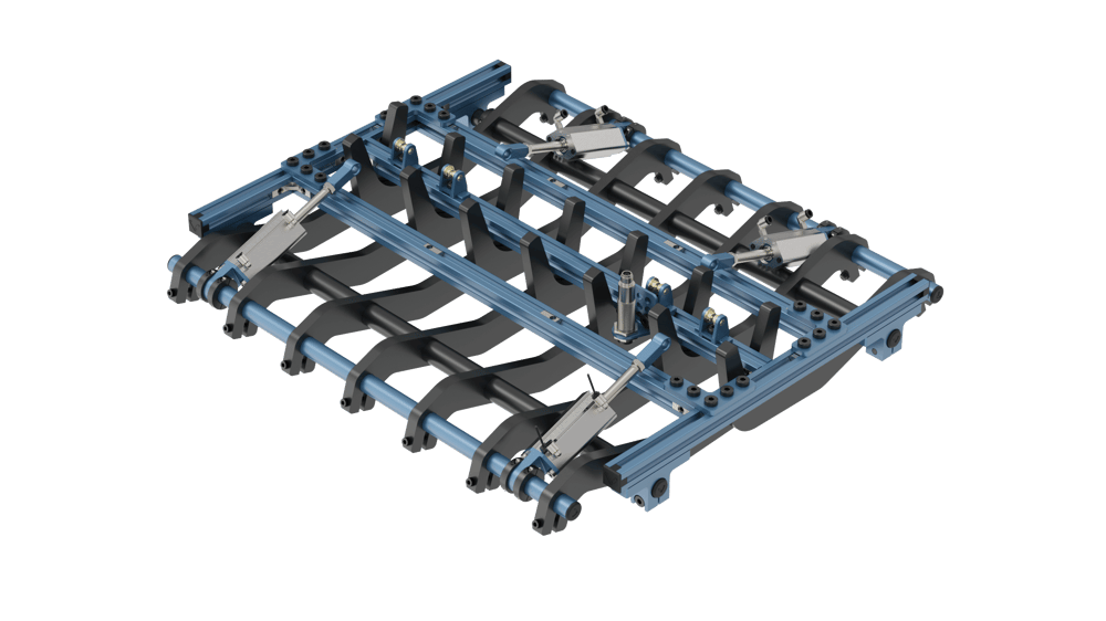
Bag Gripper Folded
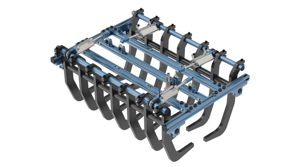
Bag Gripper Unfolded
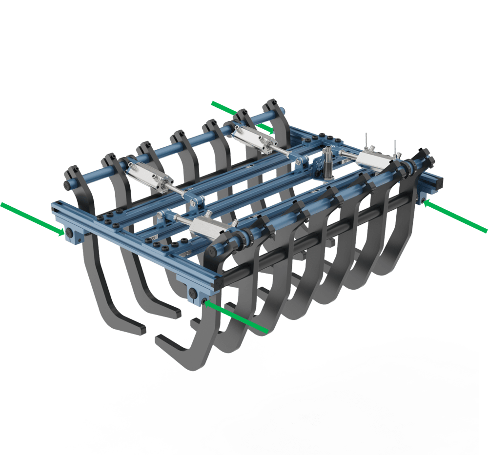
Slide the round extrusions (the ones with the finger spacers) to center the rod ends with their respective clevis joints. For each piston, insert the provided pins and external snap rings to connect the rod end to its corresponding clevis joint. The snap rings take some force to install. When done correctly, every opposing finger of the gripper should be in-line.
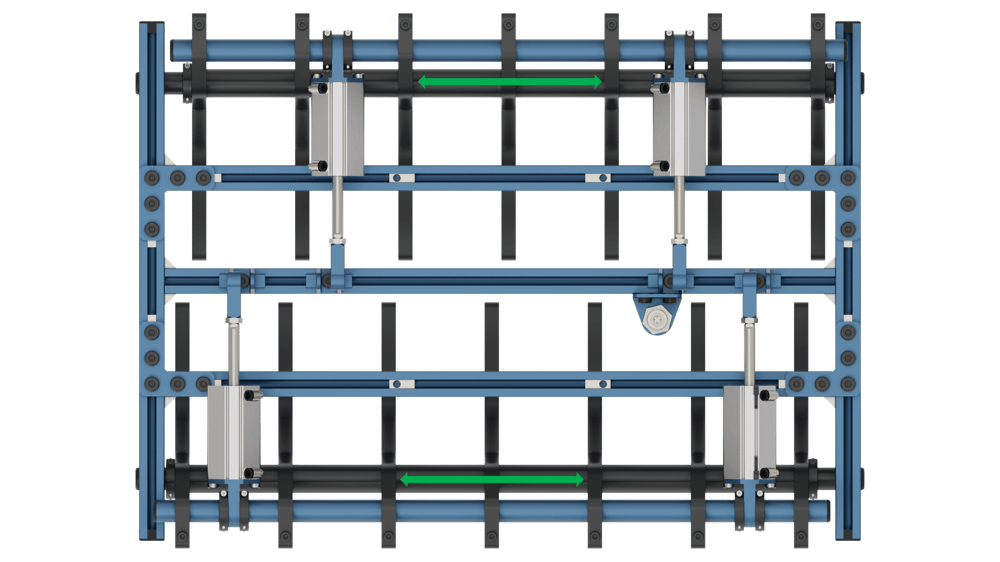
Round Extrusion Sliding Direction
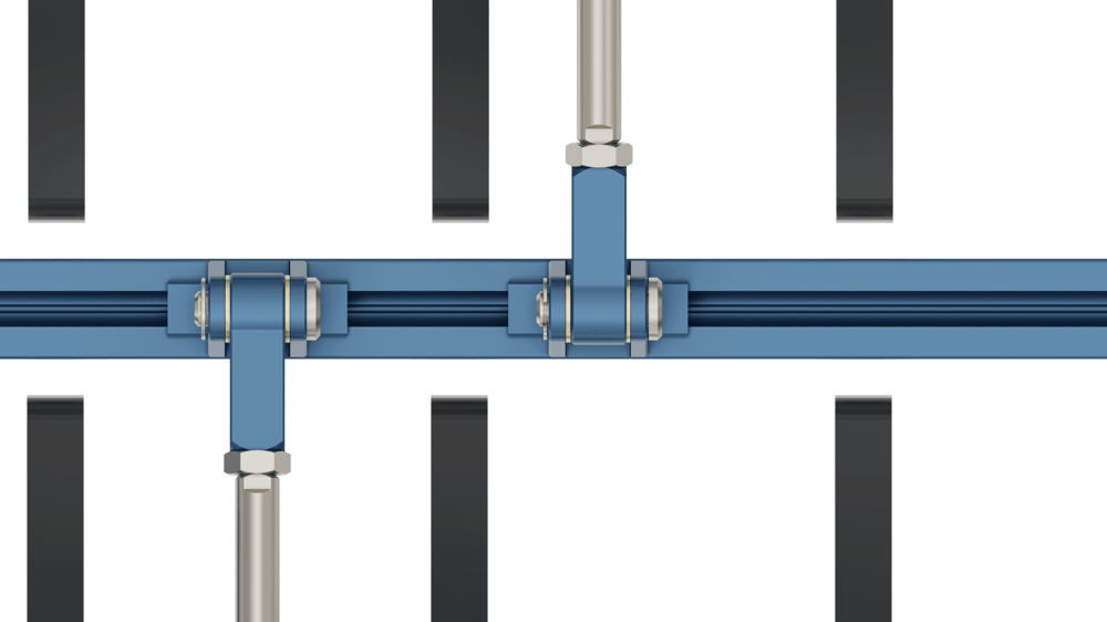
Detail View of Clevis Joint and Finger Alignment
Manually pivot the fingers open and closed, and check that binding does not occur. If it does, the most likely cause is piston misalignment. To resolve it:
Loosen the shaft collars around the piston’s back flange.Reposition the piston so that it remains in-line while the gripper moves between open and closed states.
Re-tighten the shaft collars around the piston’s back flange.
Tighten the clamping screw on each round extrusion holder.
Gripper connections
Connect the two pre-wired tube assemblies to the flow control valves outlets.
Note: The direction of the flow control valve is important in order to have proper flow. See the Pneumatic Tube Wiring Diagram for proper flow control valve orientation.Connect each flow control valve’s inlet to valve A and B on the manifold. See the Pneumatic Ecosystem datasheet for the manifold diagrams. Connect the valves according to the Pneumatic Tube Wiring Diagram. Valve A is used for opening the bag gripper, and Valve B is used for closing it.
Remove the one-touch fitting from the 8mm tube (included with the two-valve pneumatic manifold). Connect the tube to the manifold inlet and the air prep station outlet.
Connect the 8mm tube (included with the air prep station) to the air prep station inlet and your compressor outlet.
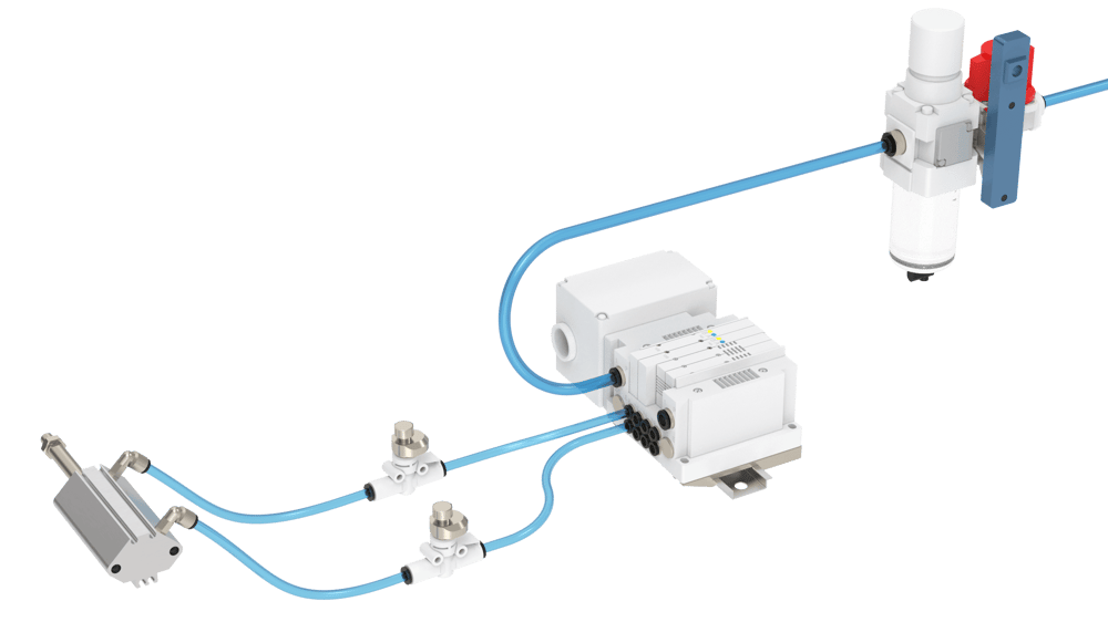
Pneumatic Tube Wiring Diagram
form the following connections to the Digital IO Module V2:
IN 0: Pneumatic actuator position sensor located at piston front (near piston rod).
IN 1: Pneumatic actuator position sensor located at piston rear (far from piston rod).
IN 2: NPN diffuse sensor.
OUT 0: Manifold connector labeled “OUT 0” (closes gripper / extends pistons).
OUT 1: Manifold connector labeled “OUT 1” (opens gripper / retracts pistons).
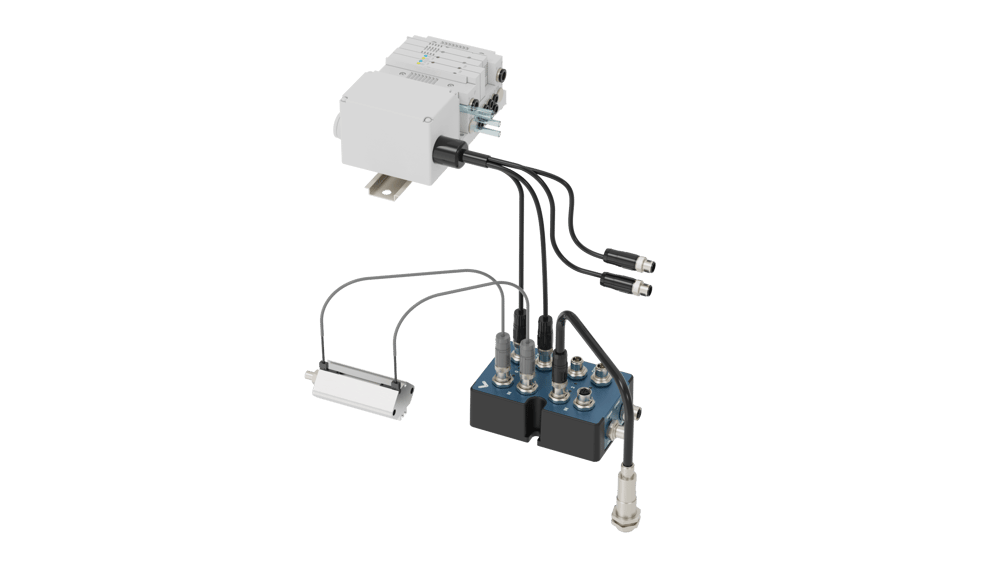
Digital IO Module Wiring Diagram
Connect the Digital IO Module V2 to MachineMotion via any control port.
Turn on MachineMotion and open its interface by typing 192.168.7.2 in the Google Chrome URL bar.
In Manual Control, select Digital Inputs/Outputs and note the Digital IO Module number.
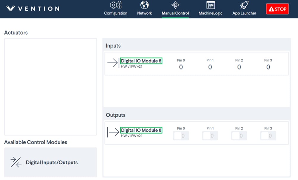
Finding Your Digital IO Number (in this case it is 8)
In Configuration, select Add Actuator. For the type of actuator, select Bag Gripper. For the Digital IO Module number, select the one found in step 8. To save the changes, the user should click the Apply Configuration button.
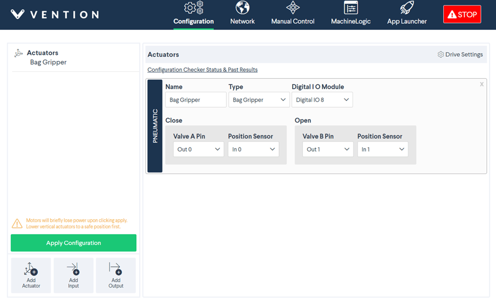
Bag Gripper Actuator Configuration Example (based on connections made in steps 1-5)
To properly set the position of the pneumatic actuator position sensor, go to Manual Control and select Digital Inputs/Outputs. Activate and deactivate the respective valves controlling the manifold (OUT 0 & OUT 1):
The pneumatic actuator position sensor located at the piston front (near piston rod) should be red when the gripper is open.
The pneumatic actuator position sensor located at the piston rear (far from piston rod) should be red when the gripper is close.
To adjust these sensors, use a small flathead screwdriver to loosen and tighten the setscrew.
Optional step: To add a bag detection sensor (NPN diffuse photo-electric sensor), go to Configuration and select Add Input. For the device number, select the one found in step 8.
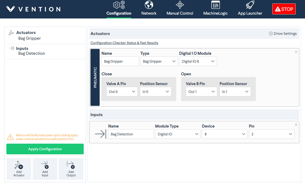
Bag Detection Sensor Configuration Example (based on connections made in steps 1-5)
Note: To properly set the sensing range of the NPN diffuse photo-electric sensor, press the buttons in the front of the sensor. See the Motor and Control Components Datasheet for more information.