|
Overview
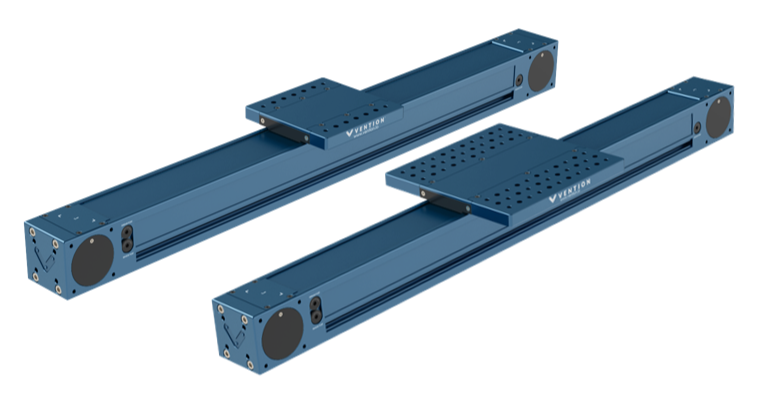
The enclosed timing belt is a high-performance actuator that opens up new possibilities, including pinch point-free configurations and the ability to work in dirty environments. This actuator comes in three configurations: standard duty, heavy duty, and dual gantry. Each configuration is available in several lengths to accommodate a range of applications. Keep reading the following technical document to understand the detailed specifications of this actuator family.
This document covers requirements for current version of MachineMotion controller. For previous version, refer to link below:
Composition
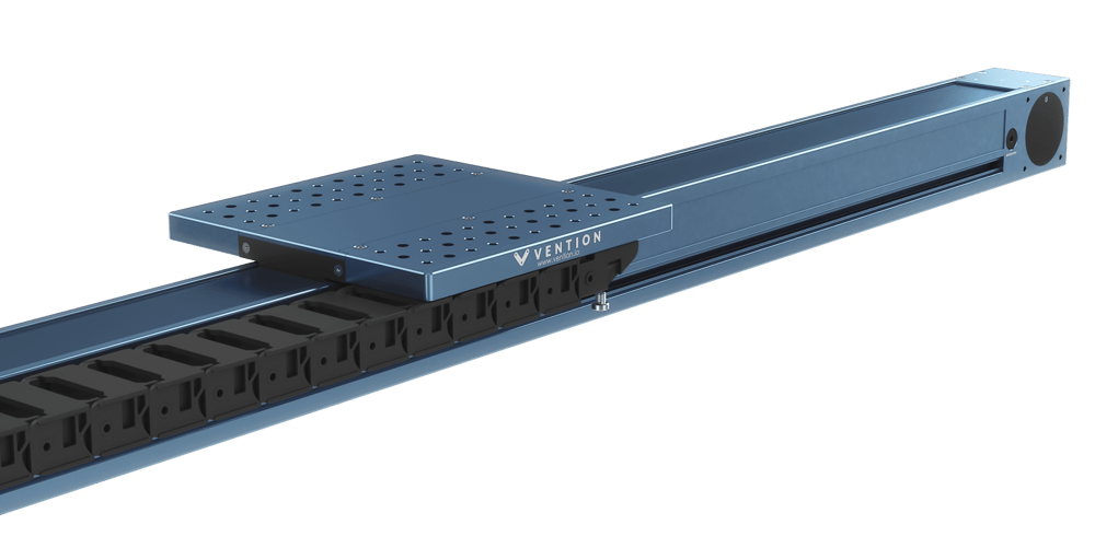
The enclosed timing belt actuator is composed of the following parts:
|
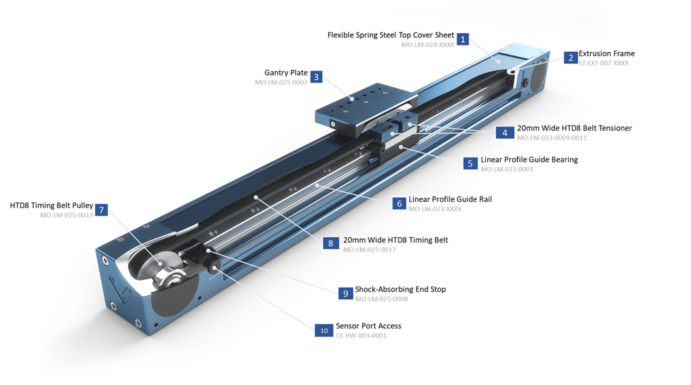
A thin spring-steel cover seals off the top of the enclosed timing belt actuator, keeping contaminants out and eliminating the chance of pinch points. Note: Cover is not load bearing. Do not apply a load to it, or it will break.
A specially designed extrusion profile provides the outer structure and mounting points.
A gantry plate forms the actuator’s main mobile structure. Use it to attach components, like a robot or another actuator, that you would like to move around.
A tensioner sets the tension of the 20-mm HTD8 belt. It is set using a single M5 screw and locked in place by the gantry bolts.
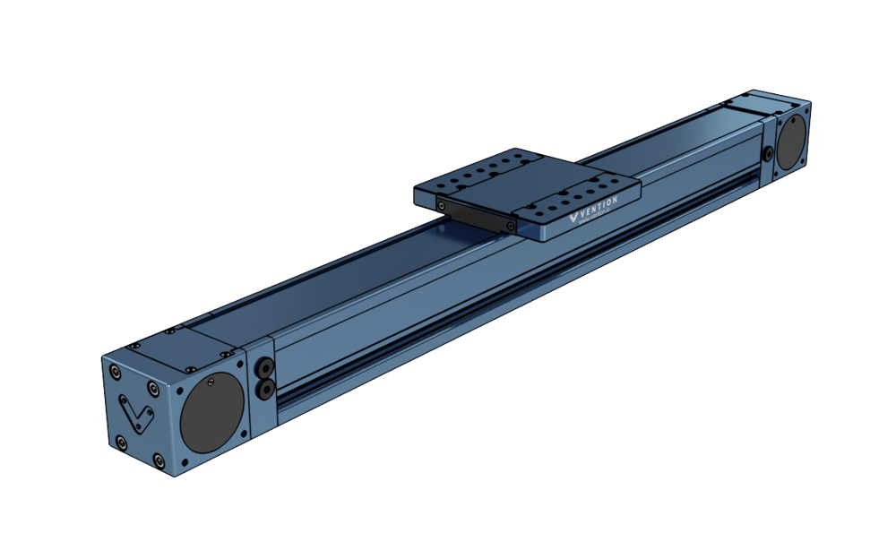
A single profile bearing carries loads on the regular enclosed timing belt (MO-LM-026-XXXX__2), as pictured, whereas two bearings are included on the heavy-duty variant (MO-LM-027-XXXX__2). These heavy-duty bearings can carry extremely heavy loads and moments.
Bearings roll along the linear profile guide rail, which is made of hardened steel and attached to the extrusion body.
The timing belt pulleys have full 180 degree belt engagement to ensure belt slip will not occur.
20 mm-wide HTD8 belt provides high-output force capacity, allowing the timing belt actuator to be used for light or heavy loads while maintaining good position accuracy.
Internal bump stops ensure that if the actuator crashes into the end of travel no components will be damaged.
Easy to access sensor ports for home and end of travel detection.
Applications
The enclosed timing belt is a robust, compact actuator that can be used in horizontal and vertical configurations. Mount it in any direction to suit your needs; its flexibility makes it suitable for a wide range of applications.
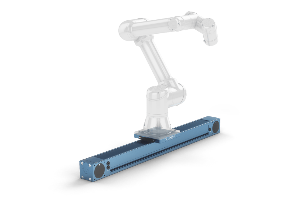
One great use for the enclosed timing belt actuator is as a range extender. Range extenders used to require multiple guide rails and a drive mechanism to move the robot around, but the new enclosed timing belt is strong enough that you can simply attach the robot to the actuator’s gantry.
The standard actuator supports the UR3, UR5, and similar robots, whereas the heavy-duty version supports the UR10, Yaskawa HC10, Yaskawa GP7/GP8, and others.
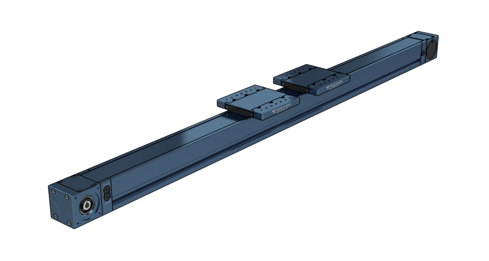
The enclosed timing belt can also be configured as a dual gantry enclosed timing belt allowing for a greater flexibility in design, as the two 180 x 180 mm gantry plates can be spaced at any interval. This variation in length creates a degree of customizability that is not afforded by the regular configuration.
|
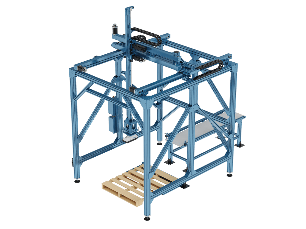
Another popular use of the enclosed timing belt actuator is as X and Y axes for palletizing applications. The robust bearing in this actuator allows for the deployment of highly rigid and durable gantry systems at size scales that were not previously possible. When mounting multiple enclosed actuators in parallel, please refer to the self aligning mount technical document found here.
|
Explore public designs to get ideas on how you could use the enclosed timing belt actuator.
Technical Specifications
The table below lists the overall performance specs for the enclosed timing belt actuator. For details see sections Available Sizes, Load Capacity, and Driving Forces.
Displacement Ratio (mm/motor rotation) | 208 |
Force per unit of input torque (N / Nm) | 30.2 |
Maximum input torque (Nm) | 61 |
Repeatability including backlash (mm) | ±0.3 |
Total Backlash (mm) | 0.25 |
Backdrive Resistance | Low |
Max Lifting Capacity (kg) | 100 |
Motor Compatibility | NEMA 34, 14mm shaft with 5mm key |
Sensor Compatability | CE-SN-004-0003 Proximity Sensor Only |
Available Sizes
The enclosed timing belt actuator is available in three duty configurations: standard duty, heavy duty, and dual gantry. Each is available in various extrusion body lengths, detailed in the table below. Note that the “length” of the actuator is defined by the extrusion body length. For the total length of the actuator add 247.5 mm.
The table below gives the weight for each size of enclosed timing belt actuator.
Standard Duty
| Heavy Duty
| Dual Gantry
| |
Extrusion Length | MO-LM-026-XXXX__2 | MO-LM-027-XXXX__2 | MO-LM-040-XXXX__2 |
585 mm | 13.79 kg | 17.51 kg | - |
855 mm | 16.49 kg | 20.34 kg | - |
1530 mm | 23.25 kg | 27.31 kg | 27.61 kg |
2295 mm | 30.90 kg | 34.91 kg | 35.62 kg |
3330 mm | 43.87 kg | 46.26 kg | 46.46 kg |
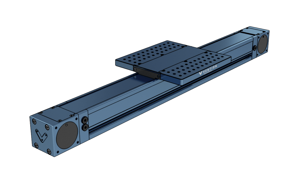
Travel
The moving gantry plates differ between the standard and heavy duty varieties. The standard actuator has a 180 x 180 mm gantry, whereas the heavy duty one is 270 x 270 mm. The dual gantry configuration utilizes two 180 x 180 mm gantry plates, which can be placed flush with one another or spaced according to the design requirements. These differences change the amount of usable travel the actuator has. The following calculations can be done to find the usable travel of an actuator:
For the travel length of MO-LM-026-XXXX__2, subtract 140* mm form the extrusion length.
For the travel length of MO-LM-027-XXXX__2, subtract 260* mm from the extrusion length.
For the travel length of MO-LM-040-XXXX__2, subtract (320* mm + gap between gantries) from the extrusion length.
*NOTE: These values include an extra 15mm needed to properly trigger home and end sensors. Add 15mm to the travel length to get the distance between hard stops.
Loading Capacity
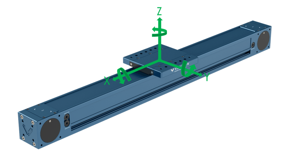
The table below shows the load capacity of the three configurations of the enclosed timing belt. Both nominal and max peak forces are specified for each type of actuator and in each direction. Use the diagram below to understand the directional load and moment capacities.
|
Standard Duty | Heavy Duty | Dual Gantry** | |
|---|---|---|---|
Part Number | MO-LM-026-XXXX__2 | MO-LM-027-XXXX__2 | MO-LM-040-XXXX__2 |
Nominal Axial Force (Fx) | |||
Max Peak Axial Force (Fx) | 1240 N | 1240 N | 1240 N |
Nominal Roll Moment (Mx) | 500 Nm | 750 Nm | 750 Nm |
Max Peak Roll Moment (Mx)* | 750 Nm | 1850 Nm | 1850 Nm |
Nominal Horizontal Force (Fy) | 3330 N | 5000 N | 5000 N |
Max Peak Horizontal Force (Fy)* | 5000 N | 7500 N | 7500 N |
Nominal Pitch Moment (My) | 630 Nm | 1250 Nm | 1250 Nm |
Max Peak Pitch Moment (My)* | 950 Nm | 2000 Nm | 2000 Nm |
Nominal Vertical Force (Fz) | 3330 N | 5000 N | 5000 N |
Max Peak Vertical Force (Fz)* | 5000 N | 7500 N | 7500 N |
Nominal Yaw Moment (Mz) | 500 Nm | 750 Nm | 750 Nm |
Max Peak Yaw Moment (Mz)* | 750 Nm | 1850 Nm | 1850 Nm |
*Note that max peak values represent the absolute maximum load. Peak loads are acceptable during one-time events such as emergency stops, but operating at peak loads continuously will cause excessive wear and significantly decrease the actuator’s lifespan.
**Note that the nominal and maximum moment of the dual gantry enclosed linear profile guide can be raised by increasing the spacing of the two gantry plates. To ensure the spacing is adequate for the application, please contact Vention’s application engineering team.
Driving Force
Output force indicates how much weight the actuator can move and how quickly it can accelerate. This force is shown as “Fx” in the Load Capacity figure. For a more in-depth explanation of driving force, see the section of our linear actuator selection guide that covers calculating actuator forces, or ask your application engineer for an explanation and help with calculations.
|
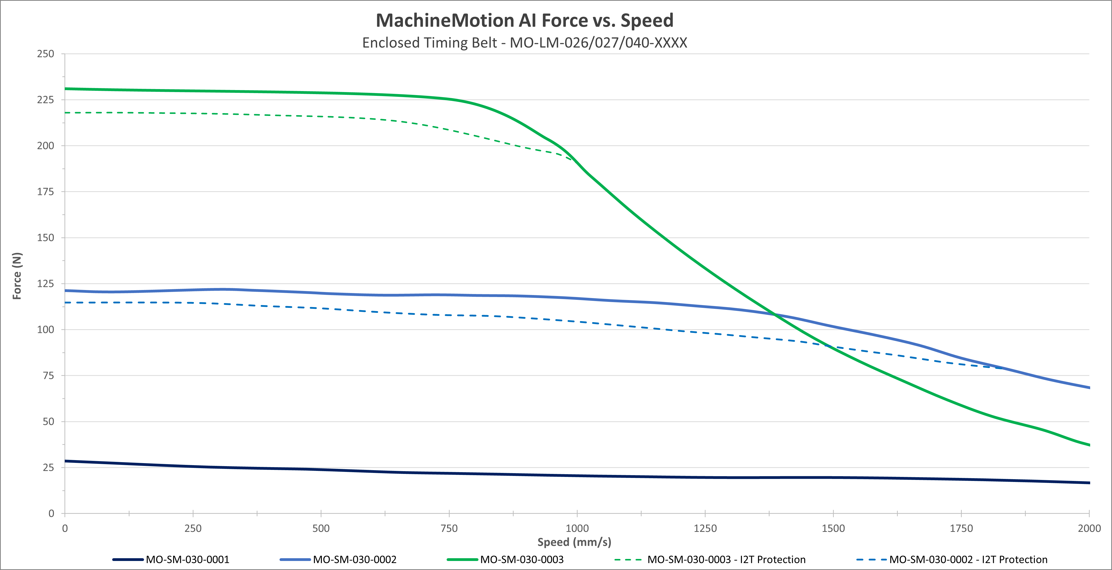
The above graph shows the output force of the enclosed axis through the range of operational speeds.
|
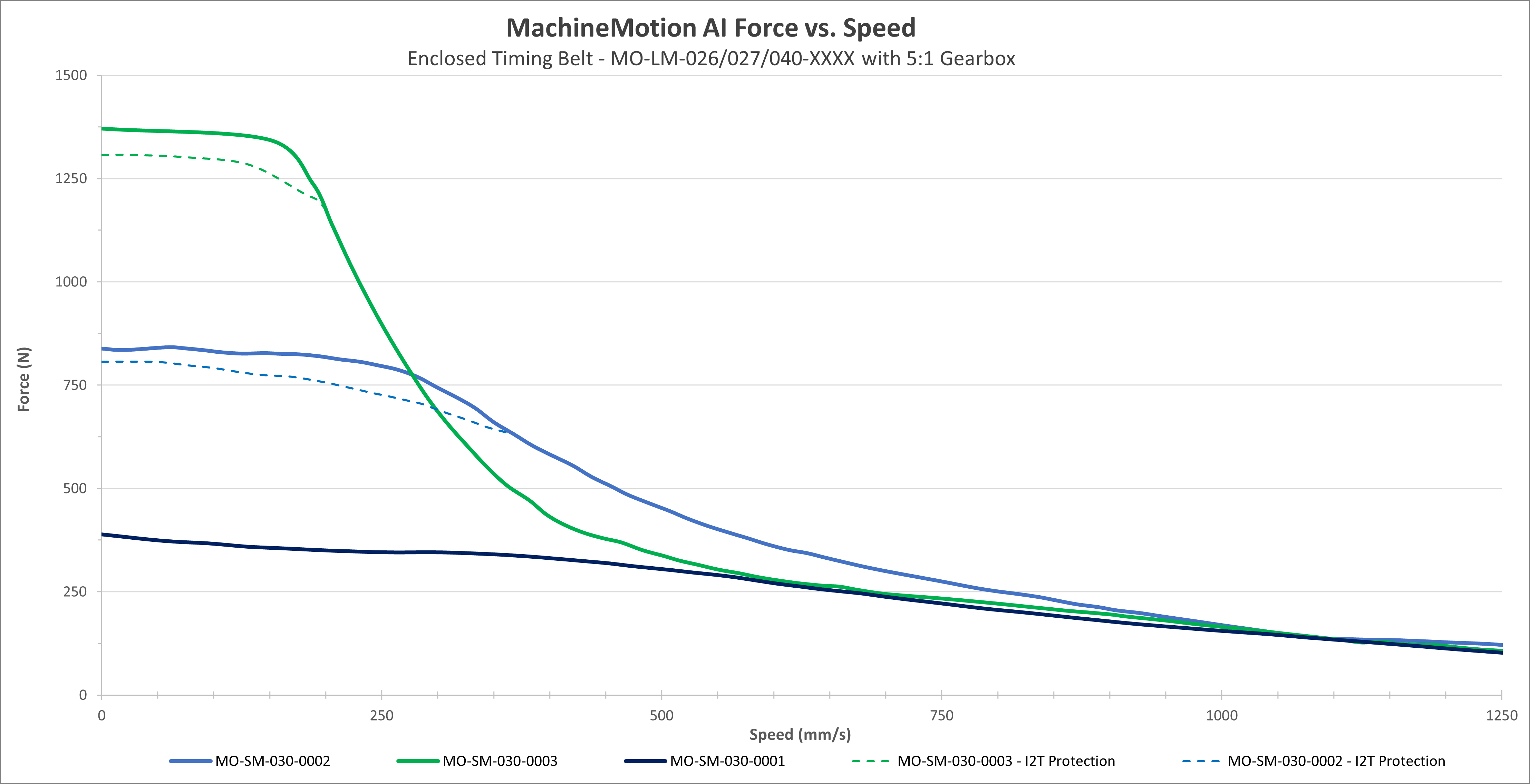
The above graph shows the driving force of the enclosed axis through the range of operational speeds when equipped with a 5:1 planetary reduction gearbox, MO-PT-001-0001. As with the earlier figure, the three different curves represent the actuator’s performance with a gearbox and the three types of NEMA 34 motors offered by Vention: MO-SM-030-0001, MO-SM-030-0002, and MO-SM-030-0003, driven by MachineMotion AI.
Notes:
These performance curves are made with our motors and controller at steady state conditions. Using others motors or controllers will have different behavior therefore performance and reliability cannot be guaranteed.
Performance curves represent peak torque and speed values. Actual continuous performance may be lower due to I²t protection in the driver. For applications involving continuous, sustained torque output, contact Vention support for thermal derating guidelines or continuous-duty application advice.
Motors are equipped with an integrated safety mechanism known as I²T protection, which prevents overheating. This function continuously monitors the current drawn by the motor over time. If the motor operates at full load for an extended period (approximately 40–60 seconds), the I²T protection engages and limits the current, thereby reducing the available torque. The dashed lines in the graph illustrate the motor’s performance under these conditions. Once the motor has cooled sufficiently, it automatically returns to normal operating mode.
When two motors are mounted on the same actuator and operated in Cyclic Synchronous Torque (CST) mode, an increase in actuator output force of 1.8× can be expected. This performance gain is only applicable when both motors are synchronized in CST mode. Motors that are synchronized—but not operating in CST mode—do not yield this increase.
Selecting the right motion parameters
Determine motion requirements: Start by defining the load that needs to be moved and the required acceleration using basic kinematic equations.
Calculate required force: Apply Newton’s second law (F = m * a) to determine the resultant force the actuator must provide.
Reference performance curves: On the Force vs Speed graphs, locate the maximum achievable speed corresponding to the required force.
If operation is near the limits of the performance curve and you observe non-smooth motion or excessive following error (discrepancy between requested position and actual position), reduce the requested speed and/or acceleration. Lowering these values decreases system demand, which improves control stability and motion quality. Reducing the inertia ratio may also help the system response (see below).
Inertia Ratio
Calculating Inertia Ratio
Vention servo motor inertia values:
MO-SM-030-0003: 3.74×10⁻⁴ kg*m²
MO-SM-030-0002: 1.48×10⁻⁴ kg*m²
MO-SM-030-0001: 0.915×10⁻⁴ kg*m²
Sample Calculation
Standard Enclosed Timing Belt actuator, with a 5:1 gearbox, moving 40kg, driven by a large motor.
Note: For most applications, an inertia ratio of 100:1 or lower is recommended. Adding a gearbox can help reduce the ratio. Generally, lowering the inertia ratio of a system results in a better response/control. If your application exceeds the recommended 100:1 inertia ratio, we encourage you to contact our Application Engineering team for a technical assessment of its feasibility.
Assembly Instructions
The enclosed axis comes completely assembled. All you need to do is install your choice of powertrain components, such as brakes, gearbox, motor, and sensors.
Sensor Installation
Sensors can be installed in any of the four sensor port locations. To install a sensor, remove the port plug and screw the sensor all the way into the hole until it bottoms out. Unscrew the sensor by a half turn to ensure it is not compressing the bump stop. Install one jam nut and tighten it to lock the sensor in place.
|
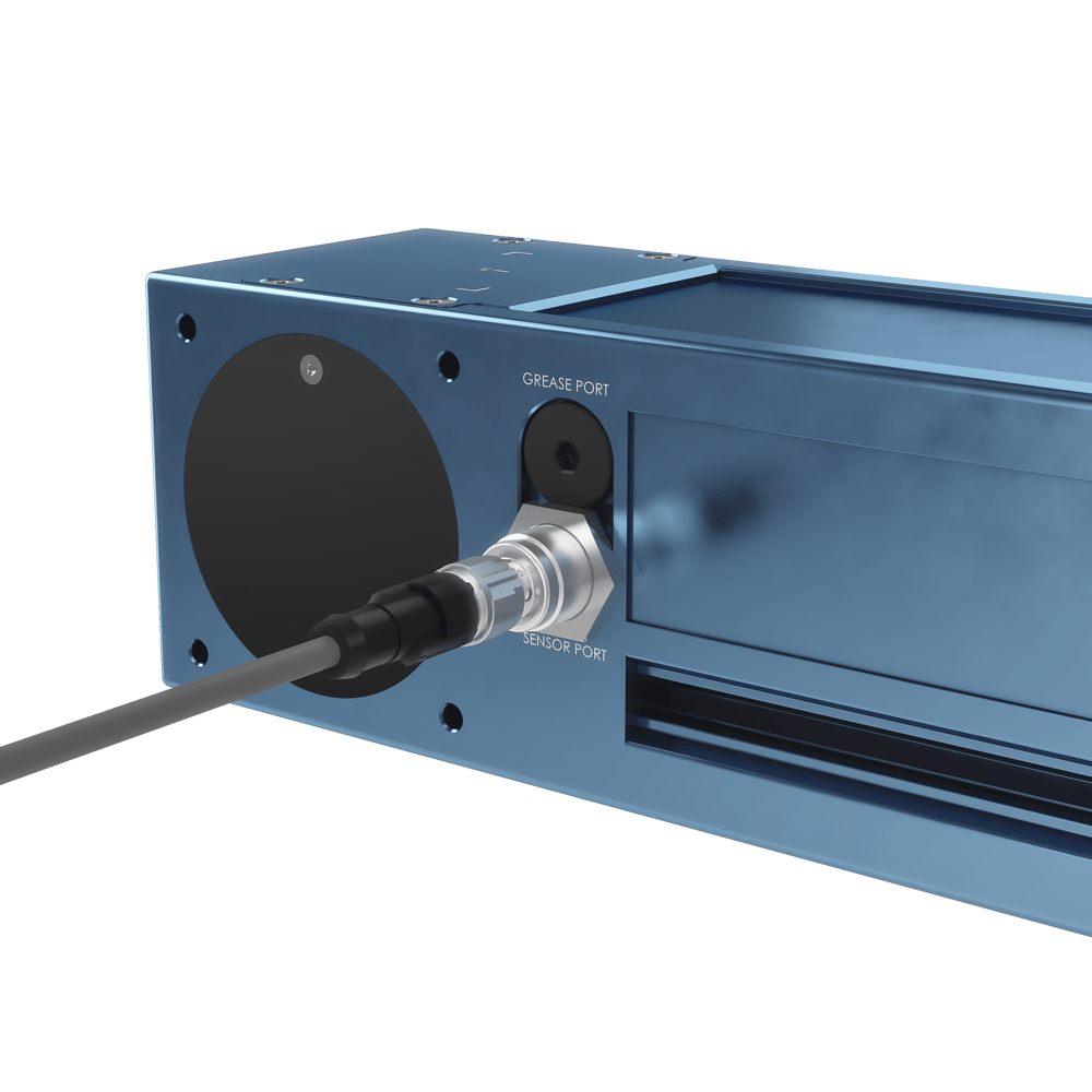
Note: The only sensor compatible with the actuator is the shielded proximity sensor (CE-SN-004-0003).
Powertrain Installation
To connect powertrain components (stepper motor, brake and gearbox), perform the following steps:
Remove the motor cover on the actuator endblock, to install the stepper motor.
Optional: If you have a brake or gearbox, connect them to the output shaft of the stepper motor using the provided M6 X 20mm fasteners.
Connect your stepper motor to the actuator using x4 M6 X 20mm fasteners (HW-FN-005-0020).
Notes:
When installing motors, apply a small amount of grease to the motor shaft so that it is lightly coated. This will reduce the possibility of fretting corrosion occurring during operation, making future removal easier.
Moreover, do not use excessive force (hammering, prying or using screws to “push” the motor) to install the motor.
Mounting Features
Once the powertrain and sensors are in place, attach the actuator to your structure by connecting any appropriate structural component to the actuator’s gantry plate. Use a minimum support distance 765 mm to ensure sufficient rigidity.
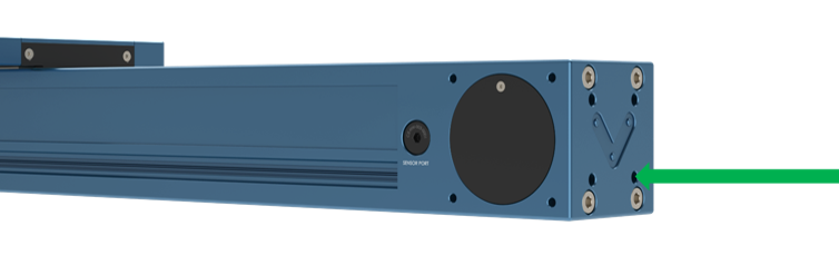
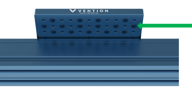
The updated enclosed timing belt actuator has two new features to improve mounting. Firstly, the end blocks how have four M8 X 1.25 threaded holes at standard Vention spacing, making it very easy to attach a gusset or other structural equipment to the end of the actuator:
|
Additionally, the counterbores on the underside of all gantry plates are now hex bores that are able to be used as a fastener counterbore or hex nut (comes included with your actuator) holder. This greatly expands the mounting options that are possible with the gantry plates.
|
You can route cables by installing a drag chain on the gantry plate’s underside, as shown below.
|
M8 x 8-mm fasteners are included with the actuator for attaching the drag chain to the gantry. If you use the included screws, you can thread into the same hole from top to bottom, expanding your drag chain installation options.
When mounting multiple enclosed actuators in parallel, please refer to the self aligning mount technical document found here.
Maintenance
For maintenance instructions please refer to the appropriate section in our Maintenance Technical Document.