|
Overview
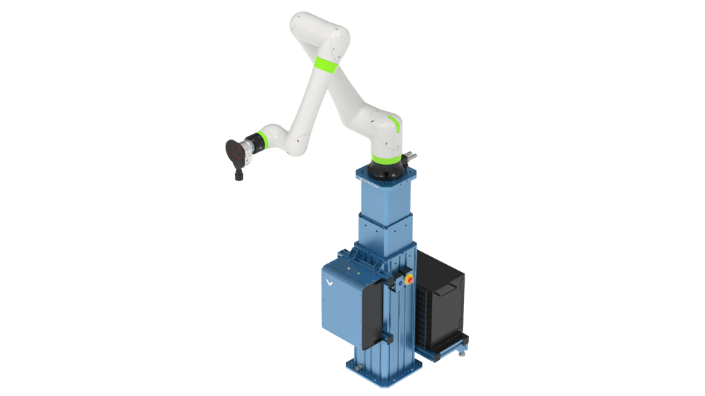
This document outlines the steps necessary to set up and program a Fanuc CRX robot in MachineLogic. By following this guide, you’ll integrate your Fanuc robot seamlessly with Vention’s motion components ecosystem.
Supported Models
CRX-5iA
CRX-10iA
CRX-10i/L
CRX-20iA/L
CRX-25iA
Required Software and Hardware
Software Options
Remote Motion Interface (R912) - (PR-FA-002-0022)
Enables remote control capabilities between MachineLogic and the Fanuc controller.
Hardware Options
CRX Safe I/O - (PR-FA-002-0021)
Integrates safety signals with the Fanuc robot.
Installation Steps
System Connection
This section describes the connection of a MachineMotion V2 to a Fanuc robot controller by way of the Robot Safety Module, in order to program the robot through MachineLogic. The Robot Safety Module acts as a 3-port Ethernet switch to enable seamless communication between the MachineMotion, the pendant, and the robot controller (see Figure 1).
Make sure that the required safety components are properly connected.
Follow the steps detailed in the Robot Safety Module User Manual.
A typical installation (Figure 1) will require the following components:
Firmware Version v3.4 or later
Fanuc CRX robot controller (R-30iB Mini Plus)
MachineMotion 2 - Four Drive or MachineMotion 2 - One Drive
Firmware Version v2.14.0 or later
3 x MachineMotion 2 Safety Extension Cable – 5m (CE-CA-102-5001)
NOTE: If your system has more than one controller set up in a Multi-Controller configuration, the safety chain which includes the Robot Safety Module and the Pendant must be connected to the parent controller.
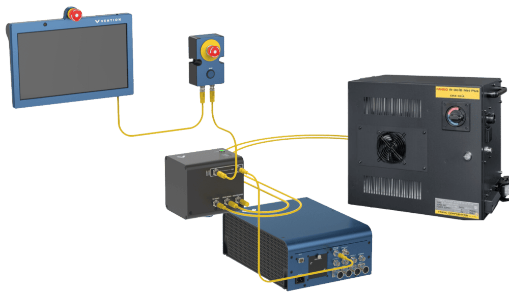 Figure 1. Safety Components Connection |
Robot Controller Configuration
1. Download Deployment Files
Download the deployment files necessary from this link:
Extract the zip file onto your USB drive. It should contain the following files:
FanucConfig_Step1FanucConfig_Step2FanucConfig_Step3
2. Load Controller Configuration Files
Step 1: Initial Setup
This step prepares the Fanuc controller in order to set each variable automatically in the following steps.
Power on the Robot Controller
Insert the USB key in the Controller USB port
Click on the iPendant icon in the lower right corner to open the virtual iPendant

Figure 5. iPendant Icon
Navigate to MENU-> 7 FILE.
Select F5 [UTIL] -> 1 SET DEVICE -> 6 USB DISK (UD1:)
Inside the directory, locate the line with an asterisk (*) to display all files.
Navigate to the
FanucConfig_Step1folder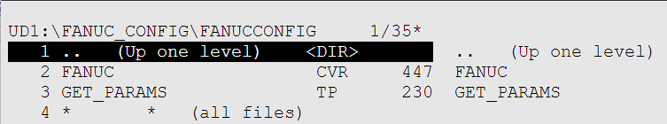
Step1_Config Content
Load the following files to the controller:
FANUC.CVRGET_PARAMS.TP
Actions
Go to the file’s line.
Press F3 [LOAD], then select YES.
If prompted with overwrite messages, press F3 OVERWRITE.
Restart the Controller
Enable the tablet teach pendant by clicking on the icon in the upper right corner of the screen.
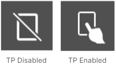
Figure 6. Enable and Disable Pendant Icons
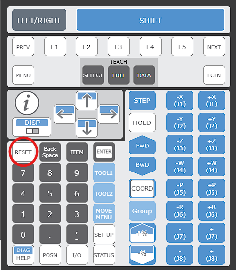
Navigate to FCTN -> 0 NEXT -> 8 START MODE -> CTRL.
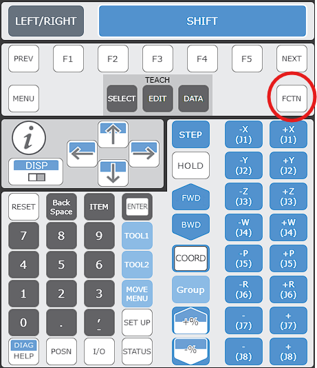
Fanuc Pendant FCTN Button
Turn off the controller using the power switch on its front.
Wait 10 seconds.
Power the controller back on.
Override Settings
To ensure compatibility, update the following settings:
Navigate to MENU -> 4 Variables.
Locate $PLST_SCHNUM and change its value to 256, then press ENTER.
Hold SHIFT + Down Arrow to speed up the search.
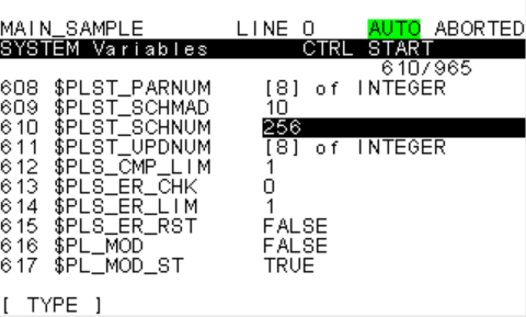
Figure 7. PLST_SCHNUM 256 value
Navigate to MENU -> 0 NEXT -> 1 Program Setup -> Numeric Registers.
Update the value to 256, then press ENTER.
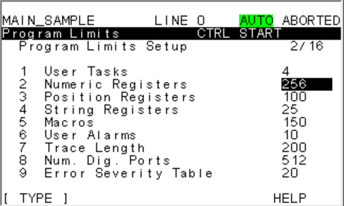
Figure 8. Numeric Register Limit to 256
Perform a cold restart by selecting FCTN -> Start (COLD).
Step 2: Upload Configuration
During this second step of configuration, we will push the necessary configuration to the controller.
Click on the iPendant icon in the lower right corner to open the virtual iPendant
Figure 5. iPendant Icon
Navigate to MENU -> 7 FILE.
Select UTIL -> SET DEVICE -> USB DISK (UD1:) -> (Up one level) -> ENTER -> FanucConfig_Step2 -> ENTER
Load the following files to the controller:
FANUC.XVRDIOCFGSV.IO
Actions
Go to the file’s line.
Press F3 [LOAD], then select YES.
If prompted with overwrite messages, press F3 OVERWRITE.
Apply DCS (Dual Check Safety)
Navigate to MENU -> 0 NEXT -> 6 SYSTEM -> F1 [TYPE] -> 7 DCS.
Select F2 [APPLY] to apply the DCS.
When prompted for a code, enter 1111 and wait until completion
When prompted, press OK.
Power Cycle the Controller
Turn off the controller using the power switch.
Wait 10 seconds
Turn the controller back on.
Step 3: Payload Creation
This step will create all the necessary payload in the controller safety settings so that MachineLogic can set different payloads during your application runtime.
Navigate to MENU -> 7 FILE.
Select UTIL -> SET DEVICE -> USB DISK (UD1:) -> (Up one level) -> ENTER ->
FanucConfig_Step3.Load the following file to the controller:
SET_PAYLOADS.TP
Execute Payload Setup
Press SELECT.
Navigate to the SET_PAYLOADS program and press ENTER.
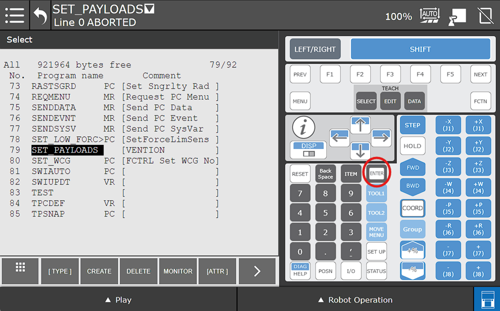
Open Set_Payloads TP
Enable the Teach Pendant. You should see this icon once it’s enabled.
Figure 6. Enable and Disable Pendant Icons
Reset any alarms that might show up.
Reset Alarms Button
At the bottom of the tablet, press Play.
Hold the Run multi-function toggle to the FWD position until program completion.
You should receive a
SYST-212 Need to apply to DCS paramalarm.
Apply DCS (Dual Check Safety)
Navigate to MENU -> 0 NEXT -> 6 SYSTEM -> F1 [TYPE] -> 7 DCS.
Select F2 [APPLY] to apply the DCS.
When prompted for a code, enter 1111 and wait until completion
When prompted, press OK.
Power Cycle the Controller
Turn off the controller using the power switch.
Wait 10 seconds.
Turn the controller back on.
Control Center
Power Up MachineMotion
Make sure wiring is properly connected in the safety chain
Confirm payload sequence
Using the Vention Pendant, go to the configuration Page
Add robot to your configuration
Select the robot you’ve purchased
Example: Select CRX 10iA/L
Apply Configuration
Wait for connection to be established
You are now ready to use your robot with a MachineLogic application!
Backup and Restore your Controller
It is normally good practice to backup your controller to ensure you can always come back to a known functional version of your controller.
Backup creation Steps
FCTN → Abort All
Menu → 7 File → Util → Set device → 6 USB Disk
You should have UD1 on the top left.
Make sure you don’t have a robot configured on your MachineMotion Pendant before continuing.
Util - 4 Make DIR - Define the name you need (e.g., BackUp Controller) - GO
You should have on the top left UD1/“Name you chose”.
Backup → 8 All of Above → YES → Then Wait until completion.
Restore your Backup Steps
Obtain a Thumb Drive:
Obtain a thumb drive with a previous MD backup for the robot you’re working on.
Insert the Thumb Drive:
Insert the thumb drive into either the USB port in the black door on the controller (UD1:) or the USB port on the right side of the teach pendant (UT1:).
Perform a Controlled Start:
Cycle power to the controller.
As soon as the robot starts to power back up, hold PREV and NEXT on the teach pendant to be taken to the Configuration Menu.
Type 3 and press ENTER to initiate a Controlled Start.
Access the File Menu:
Once the teach pendant boots back up, press the MENU button then select File -> File.
On the FILE menu, press F5 [UTIL]. If [UTIL] is not shown above F5, press NEXT until [UTIL] is shown and then press F5.
Select Set Device.
Select either USB Disk (UD1:) or USB on TP (UT1:), depending on where you inserted your thumb drive.
Navigate to the directory in which your MD backup is stored. If no files or directories are shown, you will have to press ENTER on (* * (all files)) to see the thumb drive’s contents.
Restore the Backup:
If [RESTOR] is not shown above F4, press FCTN, then select RESTORE/BACKUP to toggle between restore and backup.
Press F4 [RESTOR].
Select the type of restore action that you want:
System files (system variables, servo parameter data, and mastering data)
TP programs (.TP, .DF, and .MN files)
Application (“Non-program application files”.
Applic.-TP (All of the above, except system files)
Vision data
All of above
Confirm and Start Restore:
You will be prompted with “Restore from UT1: (or UD1:) (OVERWRT)?”. Press F4 YES.
The TP will show “Accessing device. PREV to exit.” for about 30-60 seconds, then the restore will commence. Once it begins, typical restore time is ~2-6 minutes, depending on the contents of your robot.
As many files as possible will be restored. Once the restore is complete, you will need to perform a Cold Start.
Perform a Cold Start:
Press FCTN.
Select START (COLD).
Support
For further assistance, please contact our support team at support@vention.io or calling +1-1800-940-3617 (ext. 2).