Overview
Vention offers Universal Robot Capability (URCap) extension packages which enable simple programming of Vention motion systems from the UR teach pendant. Once loaded in the UR Polyscope HMI, URCap integrations make it simple and cost-effective to create systems combining UR six-axis robot arms with Vention’s MachineMotion-controlled components.
This document describes MachineLogic for Universal Robots, a URCap that enables seamless integration of motion components such as enclosed linear axis, ball-screw linear axis, rack-and-pinion linear axis, pneumatic systems, and roller & belt conveyors. Once connected to a UR six-axis robot arm, those components enable applications like range extenders, cobot palletizers and other custom robot cells.
Note
This document provides technical specifications for Vention’s URcap (v4.x) with MachineMotion AI.
For details on Vention’s URcap for MachineMotion V2 or MachineMotion V1, refer to the Documentation for Previous Product Versions section at the end of this document.
Note
This guide assumes basic familiarity with programming via the UR Teach Pendant.
.png)
Safety Setup and Wiring
Make sure to follow the setup steps described in Universal Robot - Robot Configuration for MachineLogic Applications.
Vention’s Robot Safety Module is used to interface safety signals and Ethernet connection to the robot controller. The safety input and output allow MachineMotion to participate in a unified safety solution where the UR Controller and MachineMotion controllers are configured in a safety loop. Triggering either E-stop will cause both the UR and MachineMotion E-stops to be triggered. Please follow the Automation System Diagram (ASD) made by your Application Engineer, or one of the diagrams in the Robot Safety Module AI Datasheet.
MachineMotion setup
Machine Configuration
Vention’s URCap allows you to integrate linear, rotary and pneumatic actuators for your application.
In order to have the UR controller communicate with the components connected to the MachineMotion controller, you have to configure your Vention components within the MachineMotion environment.
Ensure that all motors are connected to their respective “Drives” ports and all I/O modules are connected to their respective “Control” ports. You can refer to the MachineMotion AI Controller User Manual for more details.
Ensure that all safety devices are correctly connected and commissioned and that a risk assessment is completed and signed.
Plug the MachineMotion into a power outlet.
Deploy the MachineMotion’s configuration following the steps described in Deploy your Configuration and Applications to a MachineMotion.
Network Configuration
The UR and MachineMotion controllers communicate using TCP/IP sockets on standard Ethernet. The UR controller has an Ethernet connector available on its bottom panel. It is recommended to use the Vention Robot Safety Module AI Ethernet connection.
In the case you prefer using the configurable LAN ports of the MachineMotion, please follow section below.
MachineMotion Network setup using LAN ethernet port
If you don’t want to use the Robot Safety Module ethernet connection, you can configure the MachineMotion LAN port to your desired IP address. You will then have to connect an Ethernet cable from the robot Ethernet port to the MachineMotion LAN port.
See MachineMotion AI Controller User Manual to learn more about how to configure the IP address of the MachineMotion.
UR Setup
Network Configuration
Ensure you follow the steps described in Universal Robot - Robot Configuration for MachineLogic Applications.
On the UR teach pendant home screen, select Menu > Settings > System > Network. Select Static Address as your network method & change the IP address to 192.168.5.3.
If you decided to not use the Vention Robot Safety Module AI ethernet connection, adjust the IP address to your custom network setup.
URCap Installation
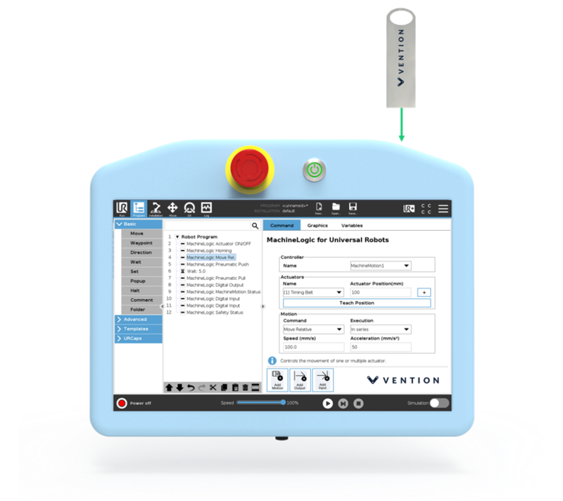
Vention’s MachineLogic for Universal Robots software is distributed on a USB flash drive and must be installed on the UR teach pendant.
Installation Steps
Step 1: Insert the USB drive
To install the URCap, insert the USB drive into the UR teach pendant’s USB port.
Step 2: Add the URCap to the UR environment
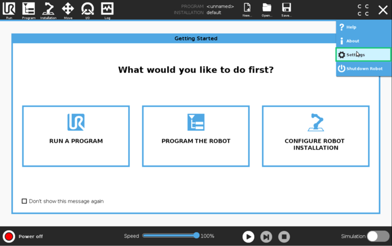
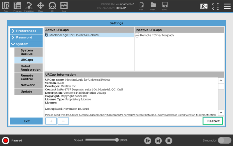
On the teach pendant home screen, select Menu > Settings.
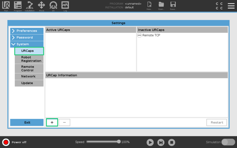
Select System > URCaps, then click the + icon at the bottom of the screen to add a new URCap to the UR teach pendant.
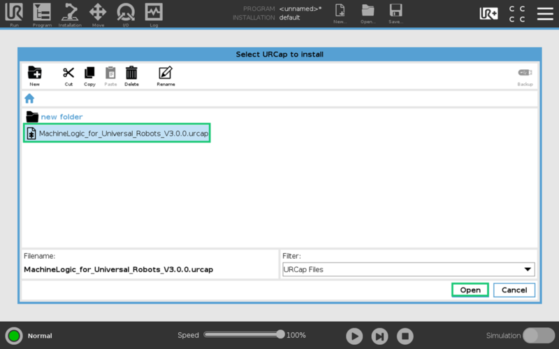
Select the .urcap file and click Open to install the URCap extension.
Step 3: Restart the UR controller
When prompted to do so, restart the UR controller to complete the installation.
URCap Configuration
On the teach pendant home screen, select Installation > UR Caps > MachineLogic Installation, to navigate to the Vention system configuration screen.
Make sure the IP address field is correctly populated. It corresponds to the IP address of the MachineMotion controller. It must be set to 192.168.5.2, as it is used for the MachineMotion controller. If you decided to not use the Vention Robot Safety Module AI ethernet connection, adjust the IP address to your custom network setup.
Then press the “Read Configuration” button.
.png)
Vention URCap configuration screen
Using the URCap
Manual Control
To manually control your actuators from the UR Teach Pendant you will need to use the Jogger feature of the URCap.
Open the Jogger by clicking on the UR+ screen located right-hand side of the top toolbar.
.png)
The input fields in the Jogger screen are explained below:
Axis Control: Choose the configured axis you want to control. The options show the friendly name given to your axis at the MachineMotion configuration step. In parenthesis, the MachineMotion port and index of the parent motor.
Current Position: Displays the current position of the chosen axis
Position increment: To jog the axis to a new position, change the position increment to the desired value and press Move button to execute a relative move. Enter a negative value in the position increment in order to move in the negative direction.
Speed and Acceleration: Will be the target speed and acceleration used when performing a Move.
Stop: Interrupt an on-going motion on the selected axis.
Set Position: You can set a new position as the current position. The value of the Position increment field will then become the new encoder position.
Home: This will move the axis in the negative direction until the home sensor is triggered. It will also reset the encoder’s zero value. This is a calibration move.
MachineMotion Control
Operational State and Safety State: display the current state of the MachineMotion controller
Enable and Disable: will energize and de-energize the MachineMotion controller.
UR Program Commands
Creating a program
Navigate to the program screen to create a robot program in the URCap.
Click the Program icon on the right-hand side of the top toolbar.
Open the URCaps drop-down,
Choose the Vention MachineLogic URCap
.png)
Opening the program screen to create a robot program
List of commands
Vention MachineLogic URCap contains 3 primary modes, which can be added to your robot program through the teach pendant screen :
The Motion commands are for moving your equipment. The available commands are:
Position Move : to move chosen axis or axes by a given distance or to a given position
Move Continuous : to move an axis at a given target velocity
Stop : to interrupt an on-going motion
Home : to move the axis to its home sensor, and reset the encoder position
Wait for Move Completion : to wait for on-going motion commands to complete, by reaching target position, distance or speed.
The Input commands are for receiving and storing status data from the MachineMotion controller and its components. The available commands are:
Get MachineMotion Safety State: to read the safety state of the MachineMotion controller.
Get MachineMotion Operational State: to read the operational state of the MachineMotion controller.
Get Axis Position: to read the current position of an axis.
Get Axis Move In Progress: to read whether or not a axis is ready to process the next motion command.
Get Digital Input Digital: to read the state of a digital input pin from a Digital IO module, or a Push Button module.
The Output commands are for performing non-motion actions on the MachineMotion controller and its components. The available commands are:
Set MachineMotion Operational State : request a change in the MachineMotion controller operational state
Set Axis Position : change the axis’ current position without moving it
Set Digital Output : change the output value of a given pin on a Digital IO module or a Power Switch module.
Using variables
You can manage the variables of your program in the Variables Setup section of the UR Teach Pendant.
To create new variables directly from a Vention URCap command, you can also use the Add button available on the right of the Variable field of the Input mode commands.
To use variable in some of your Vention URCap commands, you can click on the dropdown available next to the virtual keyboard. Change the option from Numpad to one of the available variables.
.png)
Variables Setup screen
.png)
Using variable in a “Motion - Position Move” command
You can find below the details of each available command.
Motion - Position Move
Description
Moves one or more axes immediately, to a given position or by a given distance.
This command can optionally wait for the specified motion to complete.
Parameters
Select Axis : check the checkboxes of the axes you wish you to move
Target number : for each selected axis, enter the target position or distance.
You can use the Teach button in order to record the current position as the target number. For example:
Open the Jogger menu. Ensure that the correct axis is selected.
Then:
for an “Absolute” move: Home the encoder by clicking Home.
for a “Relative” move: Enter a Position increment of 0, and press Set Position. This way, the encoder will start measuring the distance from the current position.
Then, enter a value in the Position increment field, and use the Move button ; or press Disable and physically move the axis to the desired position.
Once the axis is in the desired position, click Teach in the command screen.
Speed : desired velocity, in mm/sec
Acceleration : desired acceleration, in mm/sec2
Absolute / Relative:
chose “Absolute” to move the axes to the target positions
chose “Relative” to move the axes by the target distances
Wait for Motion Complete : check this option to wait for the motion to complete before moving on to the next command of the UR program. If unchecked, the UR command will complete as soon as the motion request has been successfully acknowledged by the MachineMotion controller.
You can use the “Motion - Wait for Move Completion” command in order to wait for the motion command to complete later on.
Usage Example
.png)
Motion - Move Continuous
Description
Moves a conveyor or rotary actuator continuously at a given speed and acceleration.
Parameters
Select Axis : select the axis you wish you to move
Velocity: Desired velocity, in mm/sec
Acceleration: Desired acceleration, in mm/sec2
Usage Example
.png)
Motion - Stop
Description
Immediately stops motion on a given axis.
Parameters
Select Axis : select the axis you wish you to interrupt motion on.
Usage Example
.png)
Motion - Home
Description
Moves an axis immediately, towards its home position, until its home sensor is triggered. The command will wait for the motion to complete, and will reset the zero position of the axis. This is a calibration move.
Parameters
Select Axis : select the axis you wish you to home
Usage Example
.png)
Motion - Wait for Move Completion
Description
Waits for an axis to have reached its target, and be ready to accept new motion commands.
Generally, motion is allowed when target is reached and when operation is enabled.
An axis is considered to have reached its target if any of these are satisfied:
it has reached its specified position or velocity for trapezoidal and continuous moves respectively
it has triggered one of its end of travel sensors
it has been interrupted by a quick stop command.
Parameters
Select Axis : select the axis you wish you to wait for motion to be completed on.
Usage Example
.png)
Input - Get MachineMotion Safety State
Description
Query the safety state of the MachineMotion.
This function is not safety rated.
Parameters
Variable: the variable in which to store the safety state.
The safety state of the MachineMotion will be one of those values:
-1corresponds to an error in the safety state0corresponds to no safety state (this would be the case for the MachineMotion AI Robot and MachineMotion AI Robot Pro models)1corresponds to an emergency stop state2corresponds to a normal safety state
Usage Example
.png)
Input - Get MachineMotion Operational State
Description
Query the operational state of the MachineMotion.
Parameters
Variable: the variable in which to store the operational state.
The operational state of the MachineMotion will be one of those values:
1corresponds to operational0corresponds to non-operational
Usage Example
.png)
Input - Get Axis Position
Description
Queries the current position of an axis.
Parameters
Variable: the variable in which to store the current position of the axis.
It will be a real number corresponding to the position of the axis, in millimetres.Select axis: The axis to read the position of.
Usage Example
.png)
Input - Get Axis Move In Progress
Description
Queries whether or not a motor has yet reached its target, and is ready to accept new motion commands.
Generally, motion is allowed when target is reached and when operation is enabled.
A motor is considered to have reached its target if any of these are satisfied:
it has reached its specified position or velocity for trapezoidal and continuous moves respectively
it has triggered one of its end of travel sensors
it has been interrupted by a quick stop command.
Parameters
Variable: the variable in which to store the current readiness of the motor.
0corresponds to the target not yet being reached, or the motor not being ready to accept new motion commands.1corresponds to the target having been reached and the motor being ready to accept new motion commands.
Select axis: The axis to read the state of.
Usage Example
.png)
Input - Get Digital Input
Description
Reads a digital input pin value from a Digital IO Module or a Push Button Module, (0 or 1), and places it in a variable.
Parameters
Variable: the variable in which to store the current state of a given digital input pin of a given module.
A pin can have a value of0or1.Port: The MachineMotion “Control” port number the module is connected to
Device ID: The module’s address
Pin: The output pin number to write on the module
Usage Example
.png)
Output - Set MachineMotion Operational State
Description
Request the MachineMotion to change its operational state.
Parameters
Enable / Disable : Request the operational state to be:
Enable : operational again
Disable : not operational. This will de-energize the connected motors.
Usage Example
.png)
Output - Set Axis Position
Description
Sets the current position of an axis to a new value. It does not move the axis.
Parameters
Set Axis Position: The new position value, in mm.
Select Axis: The axis to change the position of.
Usage Example
.png)
Output - Set Digital Output
Description
Writes a digital output pin on a Digital IO Module or a Power Switch Module.
Parameters
Port: The MachineMotion “Control” port number the module is connected to
Device ID: The module’s address
Pin: The output pin number to write on the module
Output State: The value to write to the pin. Value can be either
0or1.
Usage Example
.png)
Documentation for Previous Product Versions
MachineMotion V2 URCap
MachineLogic for Universal Robots (URCap v3.x)
Using threads in URCap v3.x
Vention instructions are not thread safe. If developing a multi threaded program, ensure that all Vention instructions are called within the same thread.