Overview
This document goes over how motors, end-of-travel sensors and linear actuators are configured in a Vention system, using a MachineMotion AI controller.
This document covers requirements for current version of MachineMotion controller. For previous version, refer to link below:
Before proceeding, we recommend reviewing the MachineMotion User Manual to familiarize yourself with the different methods of interfacing with the controller (e.g., using a computer or the Teach Pendant).
Configuration in MachineBuilder
To operate an actuator, you must first configure it:
Open your MachineBuilder design.
Open the Configuration section in the right pane.
Select the actuator or motor you would like to configure.
An axis has the following parameters:
Name: Friendly name which will be used to call the axis in MachineLogic
Type: The actuator type. It will be automatically selected based on your MachineBuilder design
5:1 Gearbox: If you have a 5:1 ratio gearbox installed on each motor of the axis, this checkbox will be checked.
Homing: The homing parameters define how an axis self-calibrates
Homing Speed: The speed at which the homing motion will occur
Homing Acceleration: The acceleration at which the homing motion will occur
.png)
Figure 1: Axis configuration parameters in MachineBuilder
A motor has the following properties:
Name: Friendly name given to the motor
Tuning Profile: This allows you to tune your step-servo motor using various profiles, to achieve the best performance for your application.
Default: the system will select the tuning profile the best adapted to your actuator type.
Position Mode: best suited for motors performing bounded motion, following a position target.
Velocity Mode: best suited for motors performing continuous motion, following a speed.
Torque Mode: best suited for motors following another motor, with tight mechanical coupling. See Synchronizing motors.
Custom: allows you to manually input the motor tuning parameters, with the help of the Customer Success team.
kp_current: Proportional gain for the current control loop. A typical value is 3.5. Increasing this improves response speed but may cause oscillation.
ki_current: Integral gain for the current control loop. A typical value is 0.0001, especially in position and velocity control modes. This helps eliminate steady-state error.
kp_velocity: Proportional gain for the velocity control loop. A typical value is 100. Higher values increase responsiveness but risk instability.
ki_velocity: Integral gain for the velocity control loop. A typical value is 0.09. It helps compensate for long-term velocity errors.
imax_velocity: Maximum integral output limit for the velocity controller, expressed as a percentage. Helps prevent integrator wind-up. Must be between 0 and 100.
kp_position: Proportional gain for the position control loop. A typical value is 0.4. Adjusts the system's responsiveness to position errors.
ki_position: Integral gain for the position control loop. A typical value is 0.0001. Reduces steady-state error over time.
kd_position: Derivative gain for the position control loop. A typical value is 0.1. Helps dampen oscillations by reacting to error rate changes.
imax_position: Maximum integral output limit for the position controller, expressed as a percentage. Limits the influence of the integral term to prevent wind-up.
velocity_feedforward: Velocity feedforward gain. Improves tracking of velocity commands by anticipating output based on target velocity. Often used in high-performance control systems.
acceleration_feedforward: Acceleration feedforward gain. Enhances responsiveness to motion changes by feeding forward desired acceleration into control output.
load_feedforward: Compensation for static load seen by the motor, specified in Amperes. Helps reduce steady-state current offsets in vertical or gravity-influenced applications.
Motor Direction: Defines the positive motion direction of the motor. See Motor Rotation Direction below.
End of travel: See end-of-travel sensor configuration details below.
Please note that these parameters will have an impact on your Digital Twin simulation, but not on your MachineMotion’s operation.Home sensor: The sensor that will be considered for the homing motions.
End stop sensor: The sensor that will be considered to detect over-travel motions.
MachineMotion port:
Port: The physical “Drives” port in which the motor will be plugged in, on the MachineMotion AI.
Index: For a given MachineMotion Port, it is the index of the motor in the motor chain.
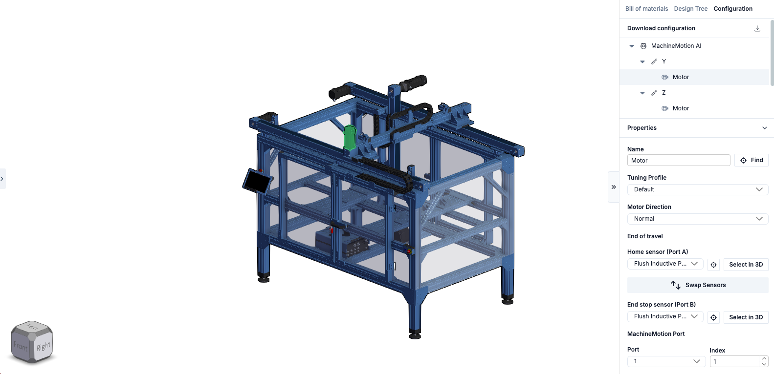
Figure 2: Motor configuration parameters in MachineBuilder
Custom Axis Type
For some applications, it may be required to configure custom axes. This can be the case when using actuators from external vendors, or when wishing to exceed speeds of 50mm/s with Enclosed Ball Screw Actuators or Enclosed Lead Screw Actuators. Critical speeds for these actuators can be found in the linked data sheet.
To configure a custom axis, select Custom in the axis’ Type drop-down menu and specify your own values for Mechanical Gain. Call Vention Support if further assistance is required.
Motor Rotation Direction
By convention, motors have a normal and a reverse rotation direction. This is an important consideration when installing the motor on an actuator. When sending motion commands to the controller (for example a relative move of +200 mm), it is important that the actuator moves in the desired direction. See figures below for motor rotations; the figures show the side of the output shaft.
Figure 3A: Normal rotation | Figure 3B: Reverse rotation |
Linear Actuator Direction
In order to satisfy the application requirements, ensure the installed positioning on the step-servo motor has the intended positive direction. The figure below shows how the linear actuator moves depending on where the motor is installed.
|
|
|
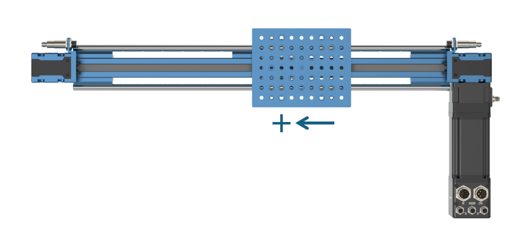
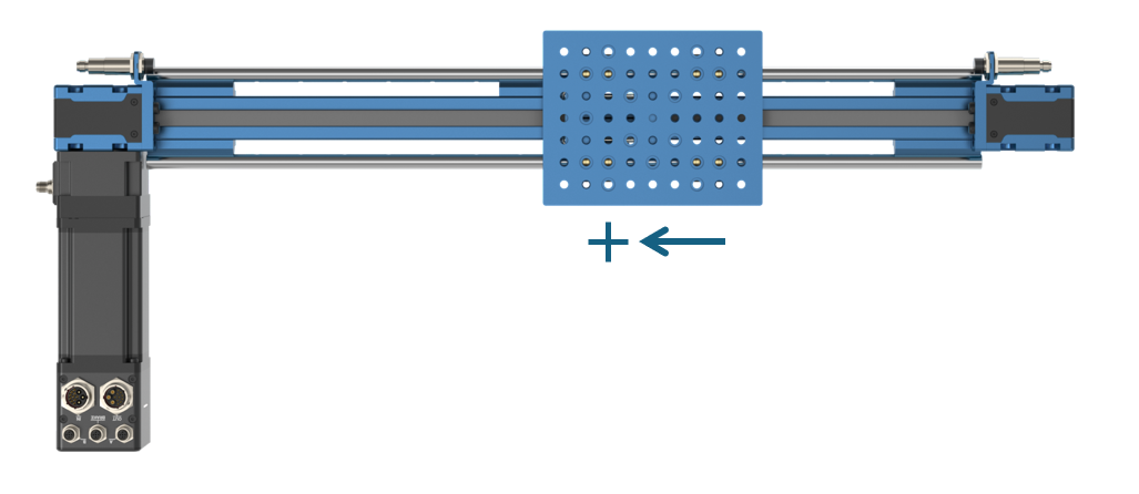 Figure 4: Actuator direction based on motor placement |
End-of-travel sensors
Linear actuators require end-of-travel sensors for two reasons:
To perform homing operations (placing the actuator in a known position, called “home” or “zero”) on the actuator. This allows the actuator to zero its position to initialize its position.
To disable motion in the event of over- or under-travel. Over- or under-travel occurs when the gantry travels beyond the limits of an actuator.
Inductive sensors are the preferred option for end-of-travel sensors since they are non-contact and less subject to environmental interference:
M18 Inductive Proximity Sensor (Sn = 10 mm): CE-SN-004-0001
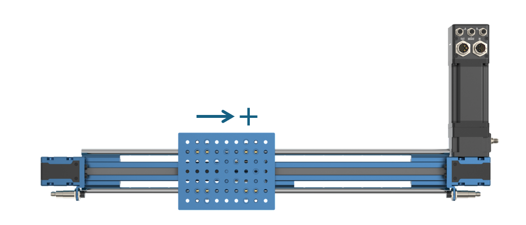
End-of-travel sensors must be mechanically installed properly on your actuator, but correct installation depends on how the motor is installed on the linear actuator. The image below details how to connect and position the end-of-travel sensors for a specific motor position:
The home sensor is positioned such that a negative motion moves towards it
The end stop sensor is positioned such that a positive motion moves towards it
In terms of wiring:
The home sensor is connected to port SENSOR A on the motor junction box
The end stop sensor is connected to port SENSOR B on the motor junction box
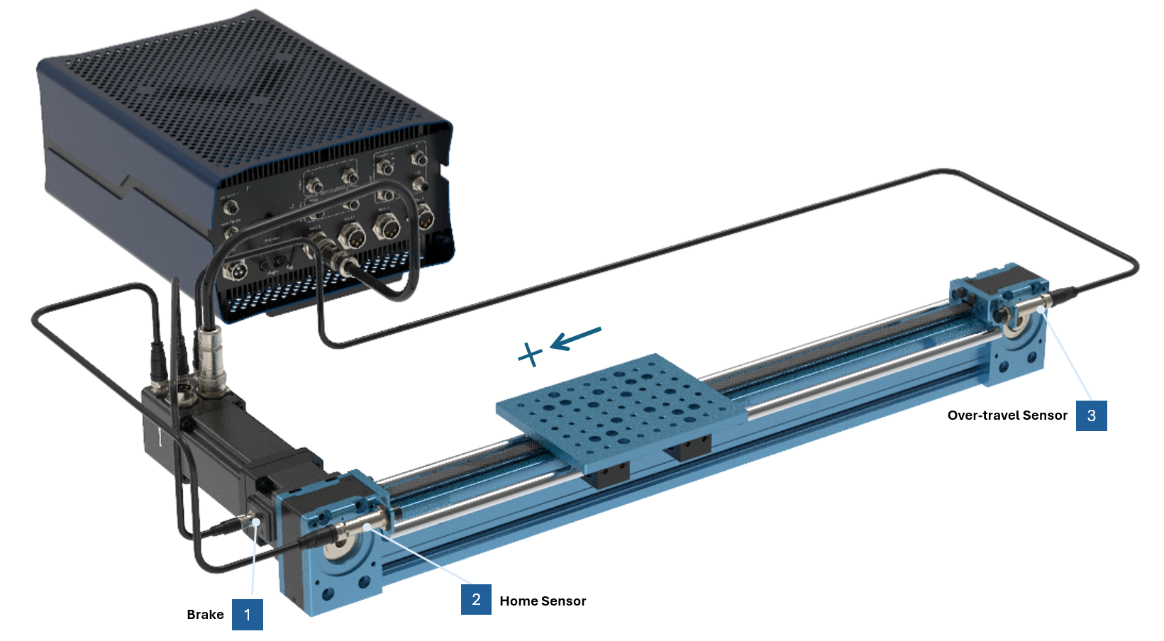 Figure 5: End-of-travel sensors connection, for a “Normal” motor direction. MachineMotion AI controller shown - CE-CL-031-3000. |
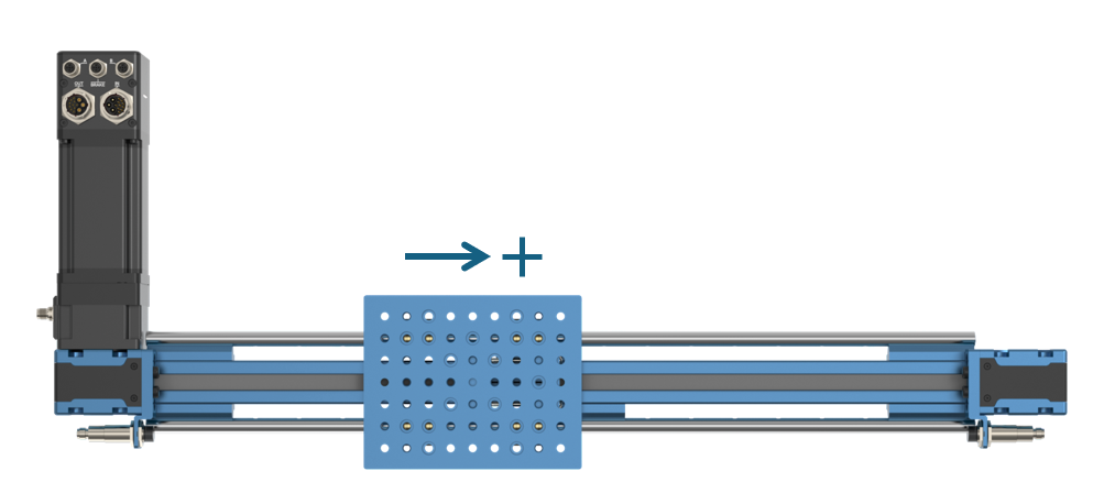
Direction Reversal
It is possible that for design reasons, the motor has to be placed at a specific place on the linear actuator (due to space or mechanical constraints). This could result in an undesired positive motion direction of the linear actuator.
To reverse your motor direction, select Reverse in the motor’s Direction drop-down menu.
Reversing the motor direction also reverses the position of the home and over-travel sensors.
Reversing the motor direction results must result in the following wiring:
The home sensor is connected to port SENSOR B on the motor junction box
The end stop sensor is connected to port SENSOR A on the motor junction box
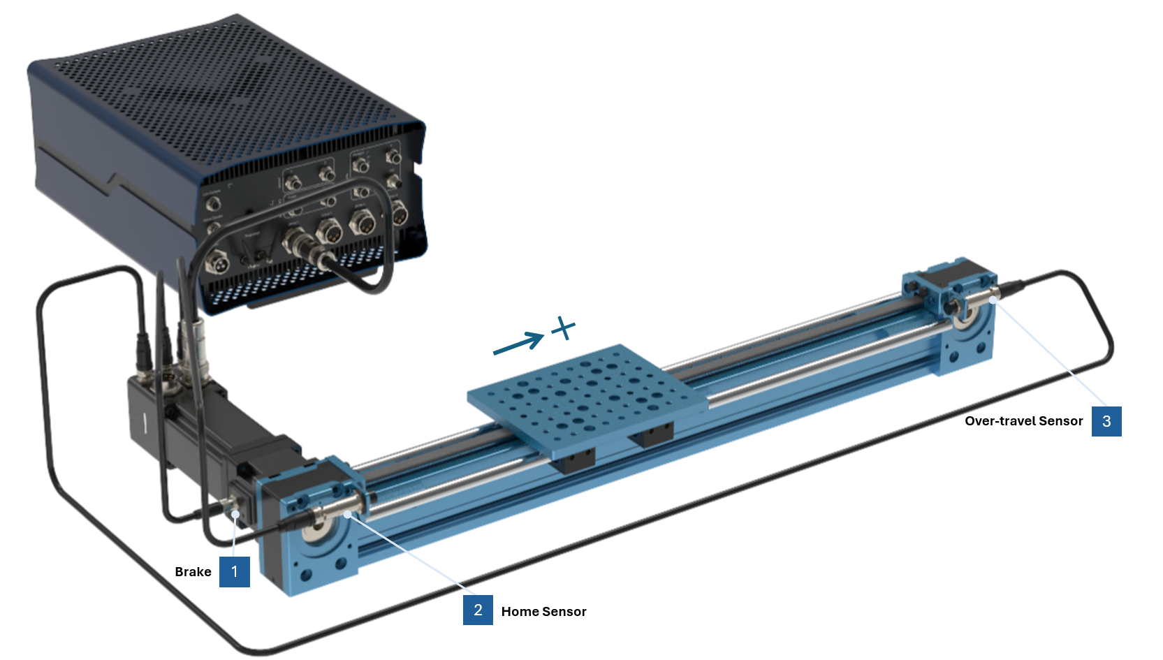 Figure 6: End-of-travel sensors connection, for a “Reverse” motor direction. MachineMotion AI controller shown - CE-CL-031-3000. |
Synchronizing motors
Plugging multiple motors into one actuator can be a solution to increase provided torque. Motors plugged into the same actuator will need to be synchronized.
The configuration will automatically nest the extra motors under the “Parent” motor.
These “Child” motors do not need to define their own end-of-travel sensors. Only jumper sensors need to be connected into the sensor ports.
To set such a configuration:
In the Configuration tab, select the child motor
Make sure the “Use {MotorName}’s sensors“ toggle is turned on.
Note: Parent motors must necessarily have their own end-of-travel sensors.
Once properly configured, these motors will be synchronized using “Cyclic Synchronous Torque” mode.
.png)
Figure 7: MachineBuilder Configuration tab, motor properties with the “Use {MotorName}’s sensors“ toggle turned on
Synchronizing actuators
Actuators can be synchronized provided that the actuator type, gearbox setting, and brake setting are identical. This configuration enables multiple actuators to move in perfect synchrony using a single motion command. Synchronization is not limited to actuators on the same chain—motors connected to different chains can also operate synchronously, as all communication is handled through the same EtherCAT network.
Follow the steps below to synchronize actuators:
In the Configuration tab, select the axis you would like to configure with multiple actuators
Click “Add synced actuator“
All of the compatible actuators will be highlighted with a pink hue. Click on the one or ones would would like to synchronize with your existing actuator.
Once your selection is complete, click “Save”.
In this configuration, each actuator will need to have its own set of end-of-travel sensors. For each actuator, make sure that they are properly attributed to one of the motors driving the actuator:
In the Configuration tab, select one of the motors driving the actuator
Make sure the toggle “Use {MotorName}’s sensors“ toggle is turned off.
Once properly configured, these motors will be synchronized using “Common Position Target” mode.
.png)
Figure 8: MachineBuilder Configuration tab, axis properties with actuator synchronization
Synchronizing motors and actuators
You can combine motor and actuator synchronization.
If the child motor is mounted on the same actuator as its parent motor, refer to the section Synchronizing motors.
It should follow its parent with “Cyclic Synchronous Torque“ mode.If the child motor is mounted on a different actuator than its parent motor, refer to the section Synchronizing actuators.
It should follow its parent with “Common Position Target“ mode.
.png)
Figure 9: Example of a cartesian gantry configuration, with synchronized motors and actuators
In the above example:
Motor Bottom Right is the parent motor, and define its own end-of-travel sensors.
Motor Top Right should follow Motor Bottom Right in “Cyclic Synchronous Torque“ mode.
Motor Bottom Left should follow Motor Bottom Right in “Common Position Target“ mode, and define its own end-of-travel sensors.
Motor Top Left should follow Motor Bottom Left in “Cyclic Synchronous Torque“ mode.
Upload / Deploy your configuration to the MachineMotion AI
Once satisfied with your configuration, you will need to deploy it to your MachineMotion AI.
You can follow the steps provided in this document.
IMPORTANT NOTE: The servo-motors may lose power during configuration, which engages the brakes. It is especially important for brakes to be installed on vertically positioned actuators.
Testing your setup
Verify the mechanical setup
Ensure your mechanical assembly is correctly setup. For example, verify the alignment of your build by following the Linear Axis Alignment Procedure. This will help you resolve issues with your synchronized linear actuators, especially when you notice only one endstop sensor being triggered instead of both.
Using Control Center
After configuring your actuators and setting up your hardware, we recommend testing your automated equipment using the Manual Control page.
Open Control Center on a PC connected to the “To PC” port of the MachineMotion (by entering “192.168.7.2” or “machinemotion.local” in the Google Chrome URL) or use the Teach Pendant.
Navigate to the Manual Control page via the top navigation bar
In the left pane, click on the axis of your choice.
You can test the functionality of your end-of-travel sensors to ensure they are properly connected. Place a metal object (like a fastener or house key) in front of your home or end stop sensors. If properly connected, the “Home” and “End” circles should turn blue.
Set a relatively low speed (recommended: 20 mm/sec) under the field Profile Speed and a low acceleration (recommended: 100-150 mm/sec2) under the field Profile Acceleration for testing purposes.
Jog your actuator at a set increment to ensure the motors are properly connected. Enter the increment at which you would like to jog your actuator (recommended: 50 mm). Click the left or right arrow to jog your actuator in that increment. Your actuator should move in that increment every time you press the left or right arrow.
.png)
Figure 10: Control Center’s Manual Mode page