|
Overview
The Robot Safety Module AI CE-SA-016-0001__2 is intended to interface a robot with the MachineMotion AI. A change in the robot’s safety state (such as an emergency stop, a protective stop, or transitioning to collaborative mode) is propagated to the MachineMotion AI, and vice-versa. A dedicated port (Reduced Speed) can accomodate one or several safety modules, such as the Auto-Reset Module AI CE-SA-019-0001__2, in order to trigger the robot’s collaborative mode with light curtains or area scanners. The Robot Safety Module AI connects directly to the MachineMotion AI on the Robot port.
This document covers requirements for latest version of Vention’s Robot Safety Module. For previous version, refer to link below:
Features
Compatible with every model of MachineMotion AI
Compatible with most robot brands
Configuration-free: plug & play
Support for robot collaborative mode (reduced speed)
RGB LED indicator for safety status (emergency stop, collaborative mode, faults)
Single-color LED indicators for power and communication status
Publishes robot’s safety state to MachineMotion AI
Propagates MachineMotion AI’s safety state to the robot
Included cables
1x Safety Extension cable - CE-CA-102-5000__3
1x Robot Safety Module “TO ROBOT” cable - CE-SA-111-2550__2
1x MachineMotion 2 Safety IN Pigtail cable - CE-CA-105-2000__2
1x Safety Jumper - CE-SA-102-0001
Safety
.png)
Vention’s safety modules perform safety functions as a part of a whole installation or machine. A complete safety system normally includes sensors or input units, logic units and contactors or output units. The manufacturer of the installation or machine is responsible for ensuring proper functioning of the whole system. The total concept of the control system into which the safety module is integrated must be validated by the user. Vention cannot guarantee all specifications of an installation or a machine without being responsible for the risk assessment and the design of the safety system. Vention takes over no liability for recommendations which are given or implied in the following description.
The following items must be taken into consideration during the design, risk assessment & installation of the safety system :
The Safety Modules shall be put into operation only after the safety functions have been tested during the commissioning.
According to EN IEC 60204-1:2018 and EN ISO 10218-1:2011 it is not allowed to restart automatically after emergency stop. Therefore the control systems of the connected devices have to disable the automatic start after emergency stop.
Opening the Safety Module or implementing unauthorized changes voids any warranty.
.png)
Functional error! Danger to life, risk of serious injuries or property damage
The Robot Safety Module may only be used in VENTION safety ecosystem;
The Robot Safety Module should be connected to the MachineMotion AI’s Robots port;
The Robot Safety Module shall be connected to a robot according to its specific wiring diagram.
No emergency stop button shall be connected to the Safety IN port;
No emergency stop button shall be connected to the safety chain of the Reduced port;
The Robot Safety Module does not monitor the input redundant signals at the From Robot port. If the connected devices do not have monitoring of its output signals, the performance level of the safety function can be reduced;
If the robot is placed in reduced (collaborative mode) with a cycle time of less than 500s, the performance level may drop to PL d.
The Robot Safety Module is designed to operate in indoor environments without dust or high humidity. Dust and dampness may lead to malfunction. Do not install or operate the Safety Module outdoors;
Technical specs
General Specifications
Item | Specification |
|---|---|
Part Number | |
Weight | 0.8kg |
Dimensions | 19.0 x 15.0 x 9.0mm |
Material |
|
Operating Temp | 0 to 40°C |
IP rating (IEC 60529) | IP54 |
Electrical Specifications
Item | Specification |
|---|---|
Nominal input voltage | 24 VDC (Class 2 or SELV power supply)* |
Input voltage range | 19.2 ~ 26.4 VDC |
Max operating power consumption | 8 W (with robot and MMAI operational) |
Short circuit protection | Internal electronic fuse, max 2.5A |
Note: In North America the Safety Module shall be supplied by a certified class 2 power supply. In Europe, the Safety Module must be supplied by an SELV circuit. When powered by the MachineMotion AI those requirements are met.
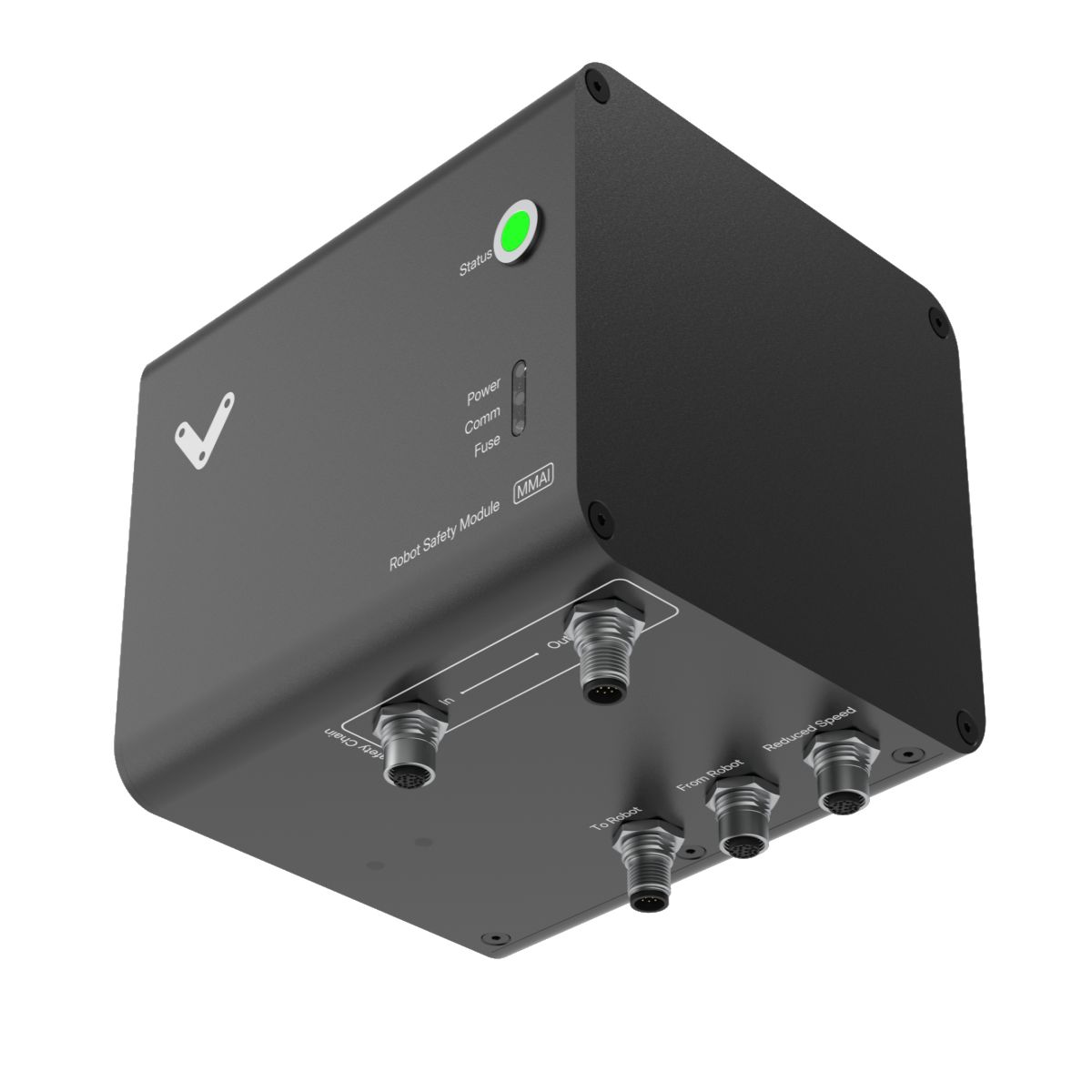
Physical Interface
 Figure 1: Physical Interface |
LED Indicators
Name | LED Color | Indicates (when ON) |
|---|---|---|
POWER | White | Power supplied to module |
COMM | White | Ethernet communication functional |
FUSE | Red | Module internal fuse tripped |
STATUS | Off | Module disconnected |
STATUS | Green | System operational |
STATUS | Orange | Error |
STATUS | Red | System emergency stop (not induced by robot) |
STATUS | Blinking Red | Emergency stop induced by robot |
STATUS | Blinking Blue | Collaborative mode (reduced speed) |
Functionality
The Robot Safety Module AI is an easy way to interface almost any robot brand with a MachineMotion AI and other safety equipments. By properly wiring the module to the robot controller, the following safety behaviors will be achieved:
When the MachineMotion AI goes into emergency stop, the robot will go into emergency stop too.
When the robot goes into emergency stop (either from a protective stop or from the robot controller pendant e-stop button), the MachineMotion AI will go into emergency stop too.
When a user manages to reset the safety system, both the MachineMotion AI and the robot will go out of emergency stop simultaneously.
When a user attempts to reset the safety system but some faults have not been cleared, both the MachineMotion AI and the robot will stay in emergency stop.
When the devices connected to the Reduced Speed port are triggered, the robot will go into collaborative mode and the MachineMotion AI will be notified.
The collaborative mode is optional (see wiring diagrams). It can be implemented if, during an intervention by an individual, a safety function (other than emergency stop) needs to be enabled, such as a speed or force limitation.
No module with an e-stop button, such as the E-stop Reset Module (CE-SA-007-0000) and the E-stop Module (CE-SA-013-0000), should be connected to the Reduced Speed port.
The Robot Safety Module AI includes a 5-port Ethernet switch that connects the robot to the MachineMotion AI, alongside with every module daisychained to other ports (such as Reduced Speed). It also includes a microcontroller that controls the LED indicators and provides internal status reporting over Ethernet. Ethernet devices connected on any of the 4 safety ports of MachineMotion AI belong to the 192.168.5.0/24 subnet.
192.168.5.0/24 | Reserved or Available |
|---|---|
192.168.5.1 | Reserved for Vention Pendant (static) |
192.168.5.2 | Reserved for MachineMotion AI (static) |
192.168.5.3 | Reserved for robot (static) |
192.168.5.4 - 192.168.5.254 | Available, can be assigned dynamically by MachineMotion AI (DHCP) |
Port definitions and pinouts
|
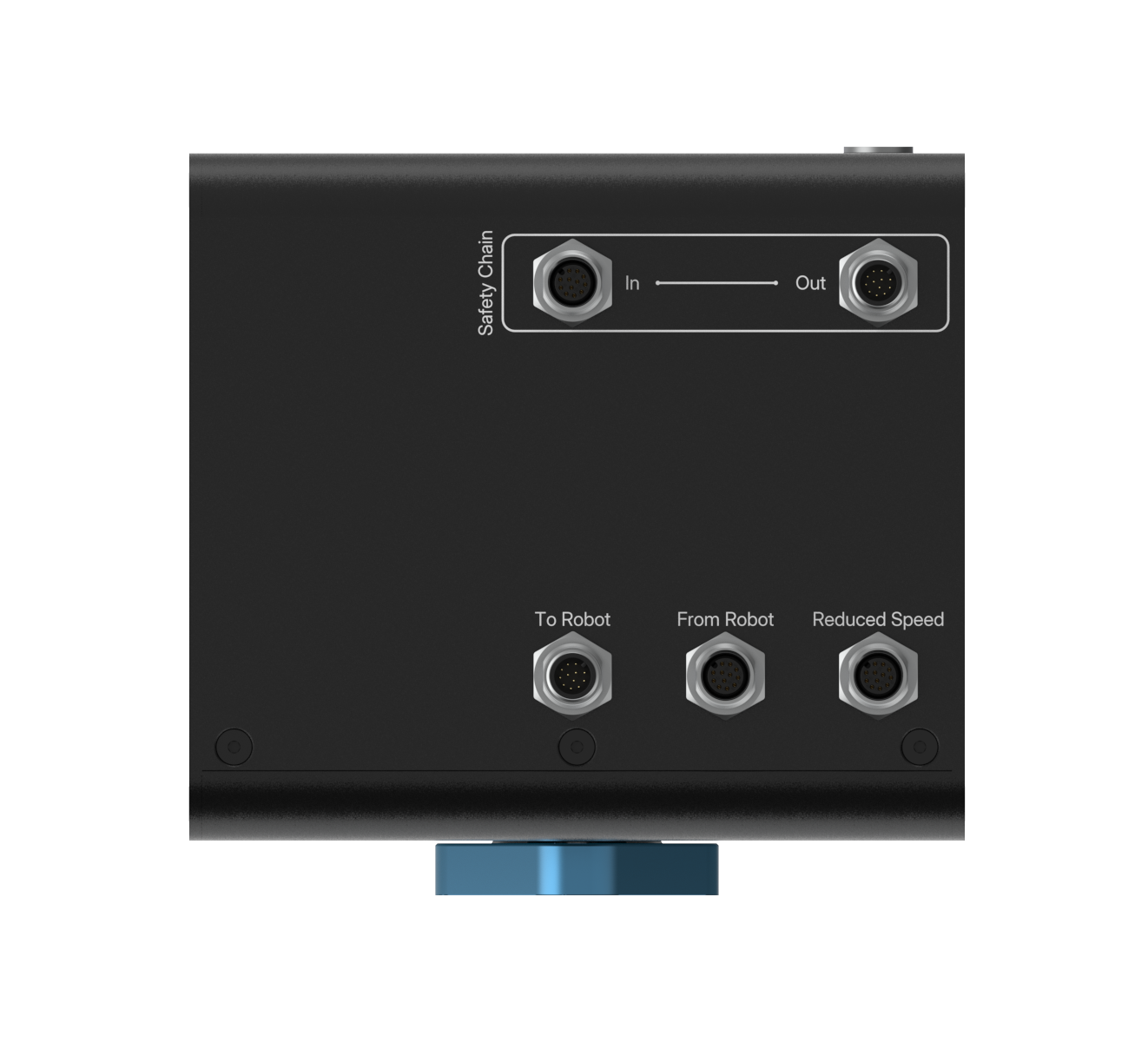
Safety Out - M12, male, 12-pin, A-Keyed
The Safety Out port connects directly to the Robot port of the MachineMotion AI.
Pin | Function |
|---|---|
Pin 1 | 24V input |
Pin 2 | 0V input |
Pin 3 | OSSD output A (to MMAI) |
Pin 4 | OSSD input A (from MMAI) |
Pin 5 | OSSD output B (to MMAI) |
Pin 6 | OSSD input B (from MMAI) |
Pin 7 | Reset input |
Pin 8 | NC |
Pin 9 | Ethernet RX+ |
Pin 10 | Ethernet RX- |
Pin 11 | Ethernet TX+ |
Pin 12 | Ethernet TX- |
Safety In - M12, female, 12-pin, A-Keyed
The Safety In port must normally be plugged with a yellow safety jumper CE-SA-102-0001 (included with MMAI).
Pin | Function |
|---|---|
Pin 1 | 24V output |
Pin 2 | 0V output |
Pin 3 | OSSD input A |
Pin 4 | OSSD output A |
Pin 5 | OSSD input B |
Pin 6 | OSSD output B |
Pin 7 | Reset output |
Pin 8 | NC |
Pin 9 | Ethernet RX+ |
Pin 10 | Ethernet RX- |
Pin 11 | Ethernet TX+ |
Pin 12 | Ethernet TX- |
To Robot - M12, male, 12-pin, A-Keyed
Pin | Function |
|---|---|
Pin 1 | NC |
Pin 2 | NC |
Pin 3 | STO to Robot dry contact output 1-1 |
Pin 4 | STO to Robot dry contact output 1-2 |
Pin 5 | STO to Robot dry contact output 2-1 |
Pin 6 | STO to Robot dry contact output 2-2 |
Pin 7 | NC |
Pin 8 | Reset output |
Pin 9 | Ethernet RX+ |
Pin 10 | Ethernet RX- |
Pin 11 | Ethernet TX+ |
Pin 12 | Ethernet TX- |
From Robot - M12, female, 12-pin, A-Keyed
Pin | Function |
|---|---|
Pin 1 | Robot STO input 1 |
Pin 2 | Robot STO input 2 |
Pin 3 | NC |
Pin 4 | NC |
Pin 5 | 0V |
Pin 6 | Collaborative mode dry contact output 1-1 |
Pin 7 | Collaborative mode dry contact output 1-2 |
Pin 8 | Collaborative mode dry contact output 2-1 |
Pin 9 | Collaborative mode dry contact output 2-2 |
Pin 10 | NC |
Pin 11 | NC |
Pin 12 | NC |
Reduced Speed - M12, female, 12-pin, A-Keyed
Pin | Function |
|---|---|
Pin 1 | 24V output |
Pin 2 | 0V output |
Pin 3 | OSSD input A |
Pin 4 | 24 VDC output |
Pin 5 | OSSD input B |
Pin 6 | 24 VDC output |
Pin 7 | Reset output |
Pin 8 | 0V output |
Pin 9 | Ethernet RX+ |
Pin 10 | Ethernet RX- |
Pin 11 | Ethernet TX+ |
Pin 12 | Ethernet TX- |
Mounting
Install the module mounting bracket (CE-HW-005-1002) to the extrusion with the screws provided (HW-FN-003-0018). Install the module onto the mounting bracket as illustrated below.
.png) Figure 3: Module Mounting | .png) Figure 3: Module Mounting |
Wiring Diagrams with MachineMotion
 Figure 4: Robot Safety Module wiring diagram |
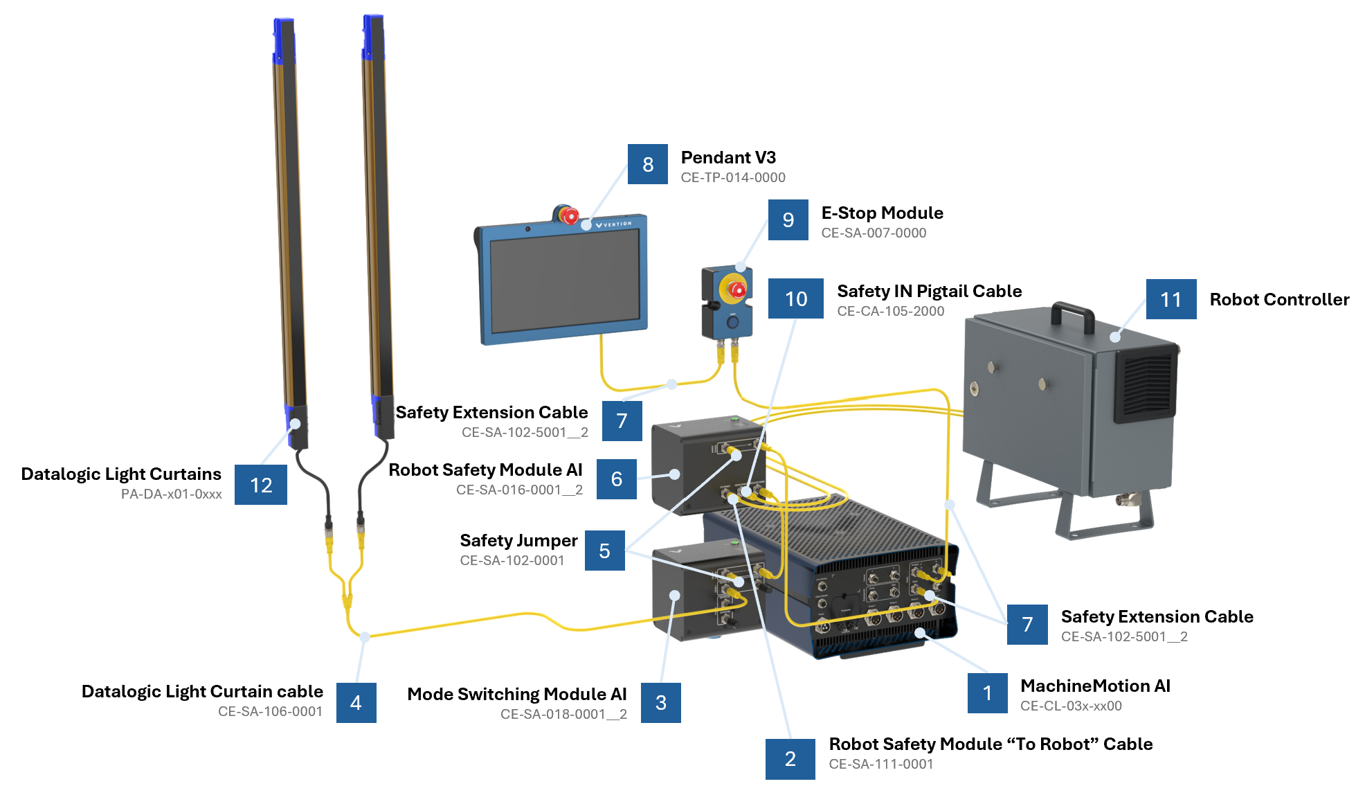 Figure 5: Robot Safety Module wiring diagram with Mode Switching Module (CE-SA-018-0001__2) |
 with callouts(2).png) Figure 6: Robot Safety Module wiring diagram with Auto-Reset Module (CE-SA-019-0001__2) |
*Note: Insert a jumper on any unused safety input for proper functionality. See table below to identify the appropriate jumper part number (included with the module).
Jumper Part Number | Description | Target module | Port restrictions |
|---|---|---|---|
CE-SA-125-0001 | M12, male, 12 pins, black jumper | Muting Safety Module AI (CE-SA-015-0001__2) | Strictly reserved for Device ports |
CE-JP-000-0002 | M12, male, 4 pins, yellow jumper | Access Request Module AI (CE-SA-017-0001__2) | Strictly reserved for End Effector port |
CE-SA-102-0001 | M12, male, 12 pins, yellow jumper | All modules | Other unused safety input ports |
Robot Wiring & Configuration
For instructions on how to wire & configure your robot controller please see the documents below:
Important information
No module with an emergency stop button should ever be placed on the Reduced Speed port.
The electronic fuse contained in the Robot Safety Module AI only protects from internal faults. 24V power outputs on the Safety In and Reduced Speed ports are not protected by the electronic fuse. The electronic fuse has an auto-retry mechanism (it does not latch faults and does not require a power cycle to reset).
Safety Data
The Robot Safety Module realizes the following safety functions :
System emergency stop output at the Safety OUT port from the Safety IN port (Estop_SafetyIN-to-SafetyOUT);
System emergency stop output at the To Robot port from the Safety IN port (Estop_SafetyIN-to-Robot);
System emergency stop output at the Safety OUT port from the From Robot port (Estop_FromRobot);
Redundant safe signal at the From Robot port from the Reduced port (Reduced_FromRobot);
System reset propagation from the Safety IN port to the Safety OUT port (Reset_SafetyOUT); and
System reset propagation from the Safety IN port to the To Robot port (Reset_ToRobot).
For each of these functions, safety data can be found in the following table.
Safety Function | PL | Cat. | MTTFd | DCavg | PFHd | Response time |
|---|---|---|---|---|---|---|
E-stop_SafetyIN-to-SafetyOUT | e | 3 | 224 | 99% | 4.29E-08 | 20 ms |
Estop_SafetyIN-to-Robot | e | 3 | 186 | 99% | 4.29E-08 | 30 ms |
Estop_FromRobot | e | 3 | 224 | 99% | 4.29E-08 | 20 ms |
Reduced_FromRobot | e | 3 | 186 | 99% | 4.29E-08 | 20 ms |
Reset_SafetyOUT | c | 1 | >100 | N/A | 1.14E-06 | Not applicable |
Reset_ToRobot | c | 1 | >100 | N/A | 1.14E-06 | Not applicable |
The above information have been calculated based on the following operation conditions:
Data | Value | Unit |
|---|---|---|
dop | 365 | days/years |
hop | 24 | hours/days |
tcycle | 8640 | s/cycle |
If the robot is placed in reduced (collaborative mode) with a cycle time of less than 500s, the performance level may drop to PL d.