Starting from version 3.3.0, a breaking change has been introduced and the configuration procedure for system version of 3.2.0 and bellow must follow this specific procedure.
Stream Motion (J519) Enables remote control capabilities between the MachineMotion AI and the Fanuc controller.
Advanced DCS Package (R859) The Advanced DCS Package includes safety options and the powerful 4D Graphics option.
SNPX (HMI Device) (R553) Enables direct, fast and structured communication to the robot controller.
Software Options Validation
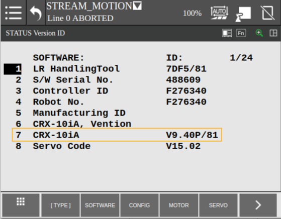
To validate that the robot controller has the necessary options installed, follow these steps:
Click on MENU
Select STATUS
Select Version ID
You can validate your controller software version on line 7 that it is indeed V9.40P/81 or later
Select CONFIG
Cursor until you findStream Motion J519, Advanced DCS Package R859 and SNPX (HMI Device) R553
If you cannot find one of the required software options, contact the support team for help to obtain the software option.
Hardware Option
CRX Safe I/O — PR-FA-002-0021 Integrates safety signals with the Fanuc robot.
Supported Robot Models
CRX Series
CRX-5iA
CRX-10iA
CRX-10iA/L
CRX-20iA/L
CRX-30iA (CRX-25iA)
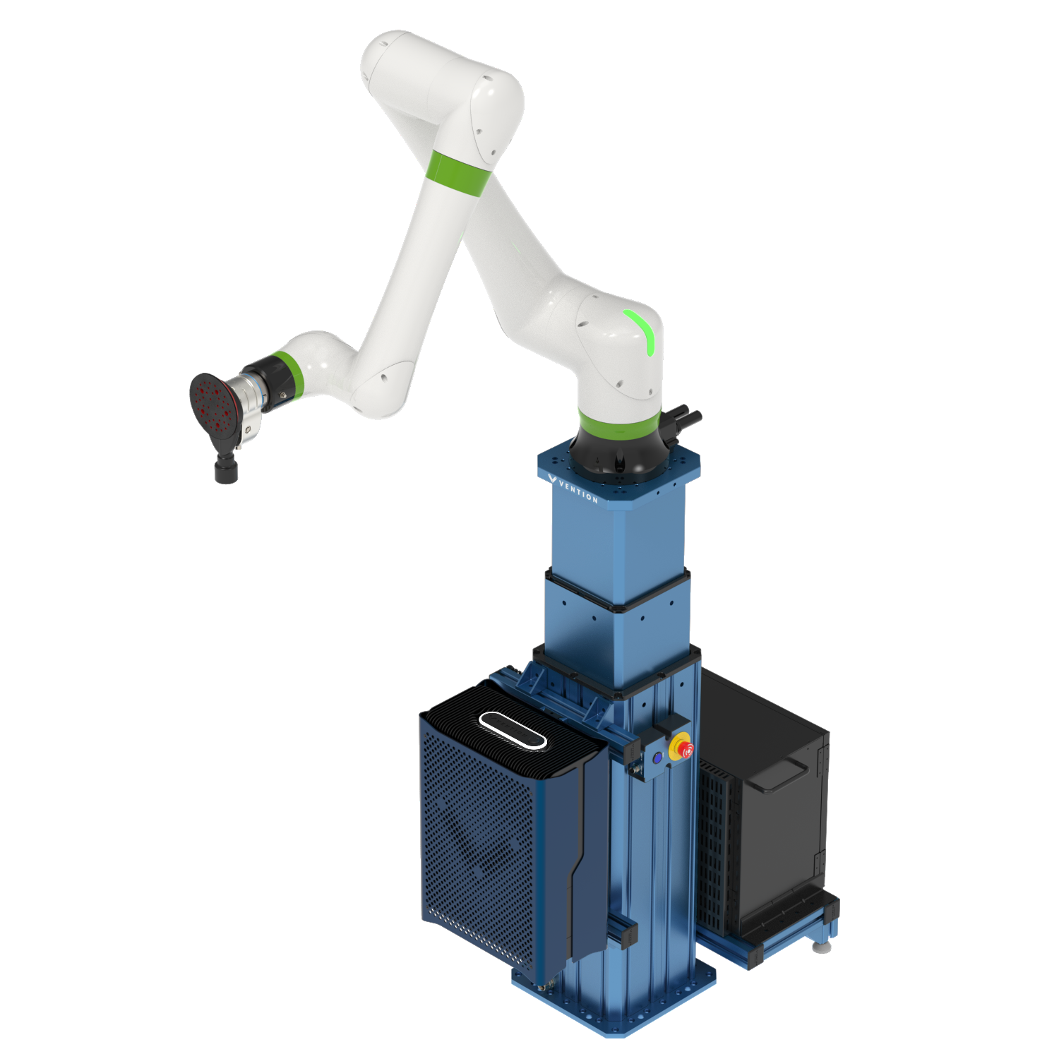
System Connection
To program a Fanuc Robot with MachineMotion AI, ensure you have the following components:
✅ MachineMotion AI Controller
✅ Pendant V3
✅ Robot Safety Module
✅ E-Stop Module with Reset
✅ Fanuc Robot with controller
✅ Safety Extension Cables
Note: This list depicts the minimum set of components needed to configure and control your Fanuc robot with MachineMotion AI. Your system may have a different set of components according to your safety needs.
Figure 1. Safety Components Connection
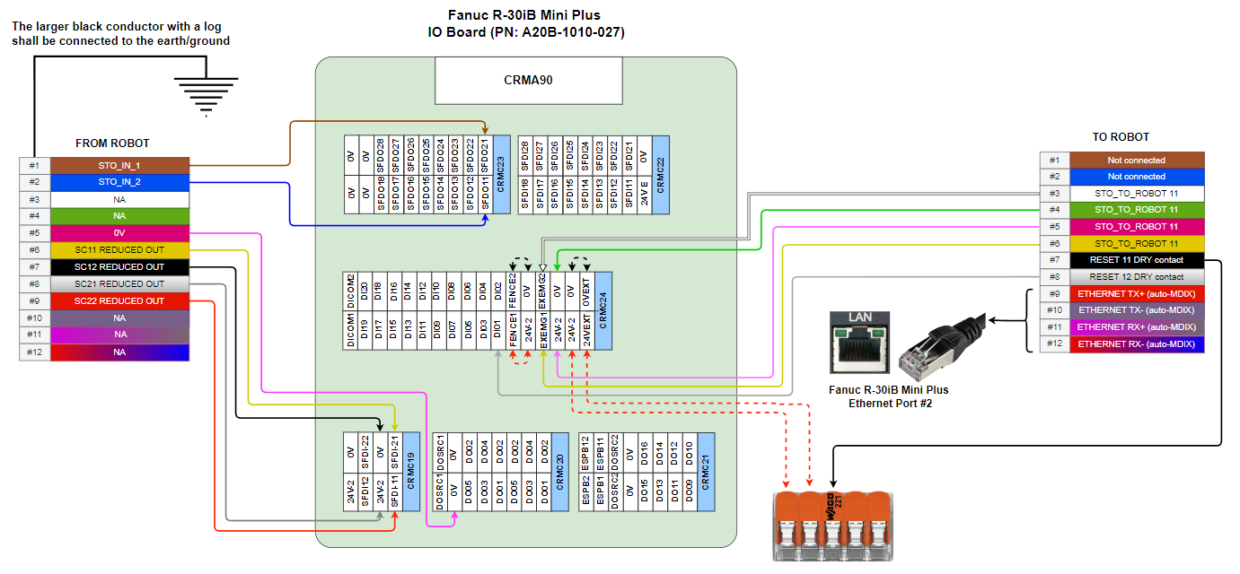
Safety Wiring
Vention’s Robot Safety Module is used to interface safety signals and Ethernet connection to the FANUC controller. Please follow the Automation System Diagram (ASD) made by your Application Engineer, or one of the diagrams in the Robot Safety Module AI Datasheet.
Safety behavior
In case of an E-stop (Vention or FANUC Pendant), or any other device that detects a dangerous situation on the Vention Safety Chain:
Safe Behavior:
MachineMotion axis falls into STO.
FANUC CRX Falls into STO or SS1, as configured.
Recovery
Pressing on the reset (blue) button will give power back to the MachineMotion and activate FANUC CRX safety signals from Robot Safety Module.
In case of a reduced speed situation from the laser area scanner:
Safe Behavior:
FANUC CRX will activate collision detection and slow down to collaborative speed.
MachineMotion is not influenced by this situation. This needs to be taken into account in the risk assessment. Axis will run at configured speed.
Recovery:
If the laser area scanner is not able to detect a human everywhere where there is a danger, but can detect the entry points, then the laser scanner should be configured with manual reset. In this case, pressing the reset button will bring back the FANUC CRX to normal speed.
If the laser scanner is able to detect a human everywhere where there is a danger, then the laser area scanner can be configured with an Auto-Reset Safety Module AI (to be determined and confirmed by risk assessment). In this case, if the laser area scanner does not detect a human in the workspace anymore, the FANUC CRX will resume to full speed.
Robot Controller Safety Wiring Diagram
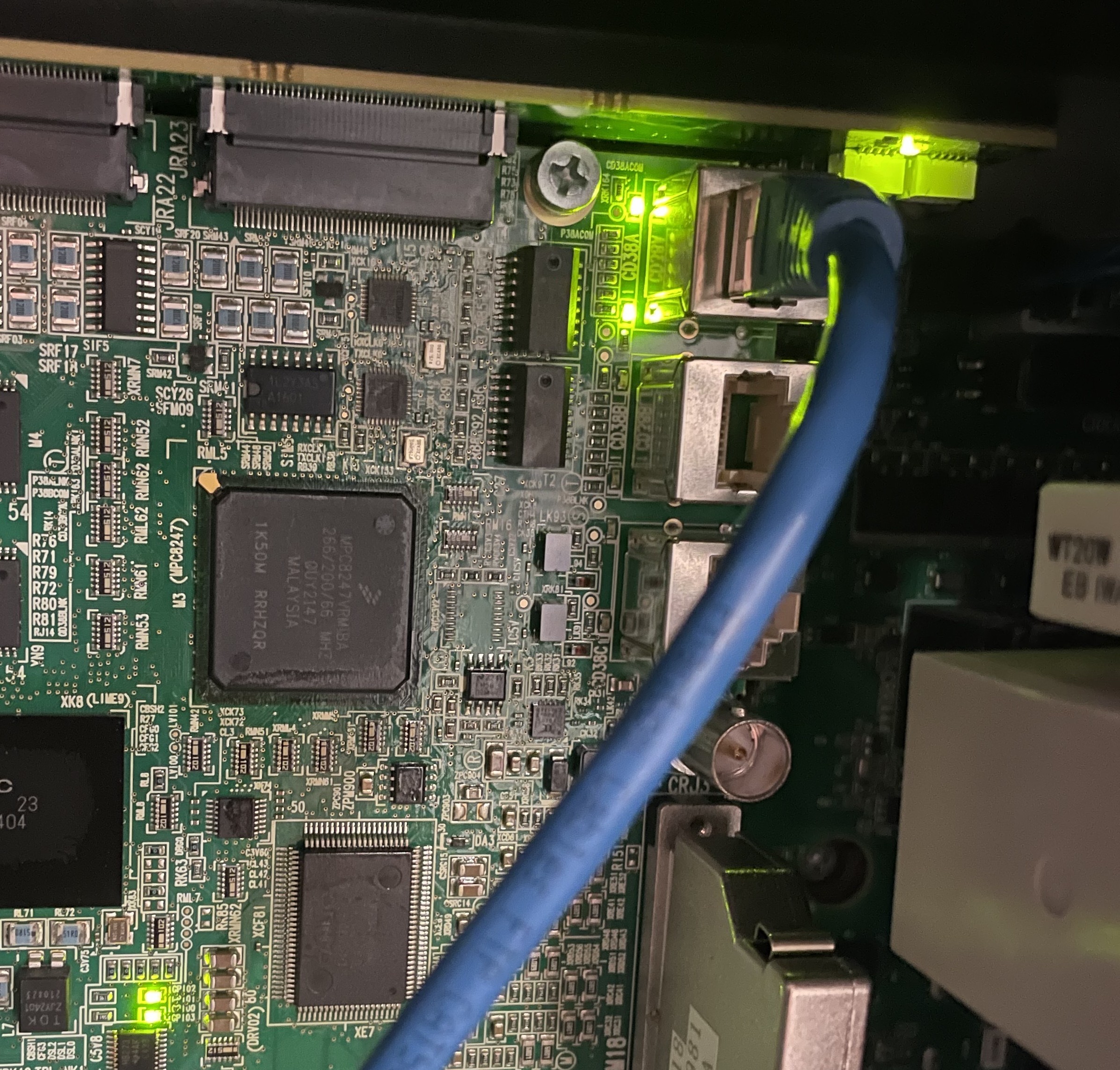
Important: Ethernet Cable Connection
To ensure proper functionality, the ethernet cable needs to be connected to the port#1 in the Fanuc controller as shown in the following picture.
Ethernet Cable Connection in Fanuc Controller (Port #1)
1. Download Deployment Files
Download and extract the deployment zip file from:
Fanuc_Configuration_Files_MMAI_VRMCS_v3.3.0
36.03 KB
You should get:
First_step
Second_step
Load the two extracted folders inside the USB key.
2. Configure Controller
2.1 Initial Setup
This step prepares the Fanuc controller in order to set each variable automatically in the following steps.
Power on the robot controller
Insert USB drive in the robot controller (not the Teach Pendant).
Open the virtual iPendant via the icon at the bottom right
Navigate: FCTN → 0 NEXT → 8 START MODE → CTRL
Power off → Wait 10 sec → Power on
Navigate: MENU → 0 [NEXT] → 1 PROGRAM SETUP → 13 Extended alarm log size
Set size value to: 1000
ENTER
Navigate: MENU → 5 FILE → F5 [UTIL] → 1 SET DEVICE → 6 USB DISK (UD1:)
Open First_step folder
Ensure you see all the following files:
FANUC.CVR
BG1.TP
MW_HOME.TP
MW_ZERO.TP
SETPAYLOAD12.TP
STREAM_MOTION.TP
Action to Load all files
Go to line 8 * (all files) → Press F3 [LOAD] → Confirm with YES
Overwrite if prompted.
Power Cycle the controller:
FCTN → Start (COLD)
2.2 I/O and Controller Configuration
2.2.1 Load Configuration Files
Open iPendant
Navigate: MENU → 0 NEXT → 6 SYSTEM → F1 [TYPE] → 6 CONFIG
Navigate to UOP auto assignment (Around line 44)
F4 [CHOICE] → 2 FULL
Navigate: MENU → 7 FILE → UTIL → SET DEVICE → USB DISK (UD1:) → Second_step
Load files:
FANUC.XVR
DIOCFGSV.IO
SYSMACRO.SV
Action to Load all files
Go to line 5 * (all files) → Press F3 [LOAD] → Confirm with YES
Overwrite if prompted.
2.2.2 Apply DCS (Dual Check Safety)
Navigate: MENU → 0 NEXT → 6 SYSTEM → F1 [TYPE] → 7 DCS
Select: F2 [APPLY]
Code: 1111
Confirm.
Wait until process is completed then Press Ok
Power off → Wait 10 sec → Power on
3. Troubleshooting
If the robot report alarms after the two steps process defined previously, here are the potential solution:
Robot Alarm
Solution
PRIO-063 Bad I/O asg: rack89 slot 1
MENU → IO → [TYPE] → Digital
CONFIG → Select any number in line with rack 89 → DELETE → YES
IN/OUT → Select any number in line with Rack 89 → DELETE → YES
Reset fault
PRIO-230 EtherNet/IP Adapter Error
MENU → IO → [TYPE] → NEXT → EtherNet/IP
Connection ADP: False
Reset fault
Connecting to the Robot Controller from MachineMotion
You're now ready to deploy your MachineLogic application from yourVention projectto the MachineMotion AI controller!
.png)
.png)
.png)