This guide will outline how to use the FANUC Extension for MachineMotion. This plugin allows you to control the Vention ecosystem from the FANUC pendant, and program in a Parent-Child architecture. The FANUC controller will be the parent and the Vention controller will be the child.
Previous versions
This user manual covers Vention’s FANUC Extension for MachineMotion AI. For details on previous releases of Vention’s FANUC Extension for MachineMotion, refer to the Documentation for Previous Releases section.
Note
This guide assumes basic familiarity with FANUC programming.
There are two aspects of this integration:
Safety—ensuring an emergency stop in one system triggers the entire system.
Communication—sending signals and/or commands back and forth.
.png)
Figure 1: FANUC with MachineMotion AI
Safety
Vention’s Robot Safety Module is used to interface safety signals and Ethernet connection to the FANUC controller. Please follow the Automation System Diagram (ASD) made by your Application Engineer, or one of the diagrams in the Robot Safety Module AI Datasheet.
Follow the setup steps described in FANUC - Robot Configuration for MachineLogic Applications.
MachineMotion setup
Machine Configuration
Ensure that all motors are connected to their respective “Drives” ports and all I/O modules are connected to their respective “Control” ports. You can refer to the MachineMotion AI Controller User Manual for more details.
Ensure that all safety devices are correctly connected and commissioned and that a risk assessment is completed and signed.
Plug the MachineMotion into a power outlet.
Deploy the MachineMotion’s configuration following the steps described in Deploy your Configuration and Applications to a MachineMotion.
Network Configuration
The FANUC controller needs to be connected via Ethernet to the Vention MachineMotion. It is recommended to use the Vention Robot Safety Module AI Datasheet ethernet connection.
In the case you prefer using the configurable LAN ports of the MachineMotion, please follow section below.
MachineMotion Network setup using LAN ethernet port
If you don’t want to use the Robot Safety Module ethernet connection, you can configure the MachineMotion LAN port to your desired IP address. You will then have to connect an ethernet cable from the FANUC ethernet port to the MachineMotion LAN port.
See MachineMotion AI Controller User Manual to learn more about how to configure the IP address of the MachineMotion.
For example, with the following MachineMotion network settings:
IP: 192.168.0.2
Netmask: 255.255.255.0
Gateway: 192.168.0.1
You will then have to change the FANUC settings in the FANUC Hostcomm menu:
Change your Client Tag to 192.168.0.2
Change the FANUC TCP IP address to be on the same subnet, like 192.168.0.3 for example.
FANUC Extension installation
Note
To run the FANUC extension, the following FANUC options are required:
Advanced DCS Package (R859)
KAREL (R632)
User Socket Messaging (R648)
This extension has been developed on Karel versions V9.40P/52 and V9.40P/80.
Ensure that options R859 - Advanced DCS Package, R632 – KAREL and R648 – User Socket Messaging are installed on the CRX controller, you can navigate in the legacy menu to : STATUS > Version ID > arrow right > ORDER F1. Refer to FANUC documentation for detailed instructions on how to install options, or reach out to Vention’s customer success team.
To install the MachineMotion FANUC extension, perform the following steps:
Copy files
How to copy files from a USB stick plugged into the Teach Pendant
Insert the provided USB stick containing the MachineMotion FANUC extension into the FANUC Pendant USB port.
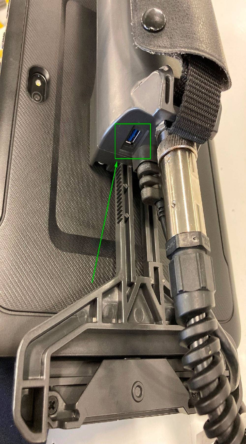
Figure 2: Back of the FANUC Teach Pendant
A popup will appear, click on : Import files from the USB memory.
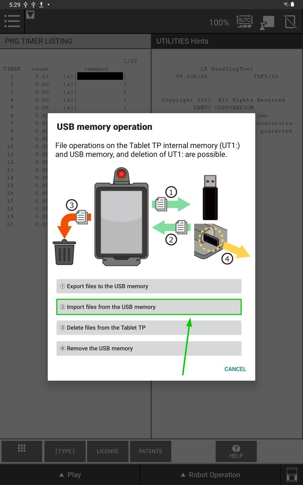
Figure 3: FANUC Teach Pendant Popup
Click on: Select Folder, to choose the files to import.
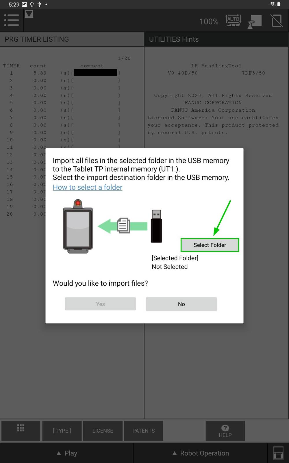
Figure 4: FANUC Teach Pendant “Select Folder”
Click on the Burger Menu on the top left.
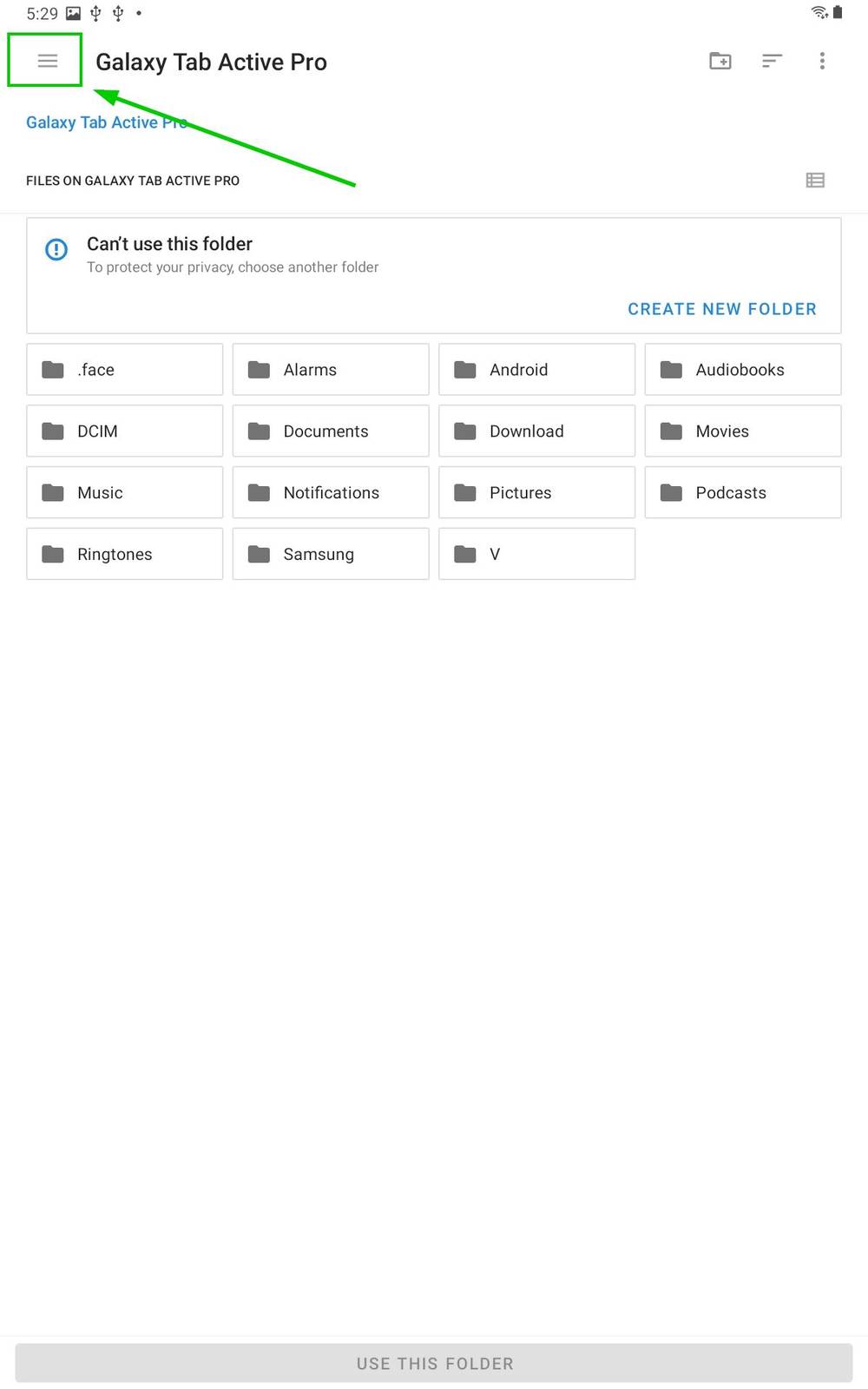
Figure 5: FANUC Teach Pendant Navigation
Select the Vention USB.
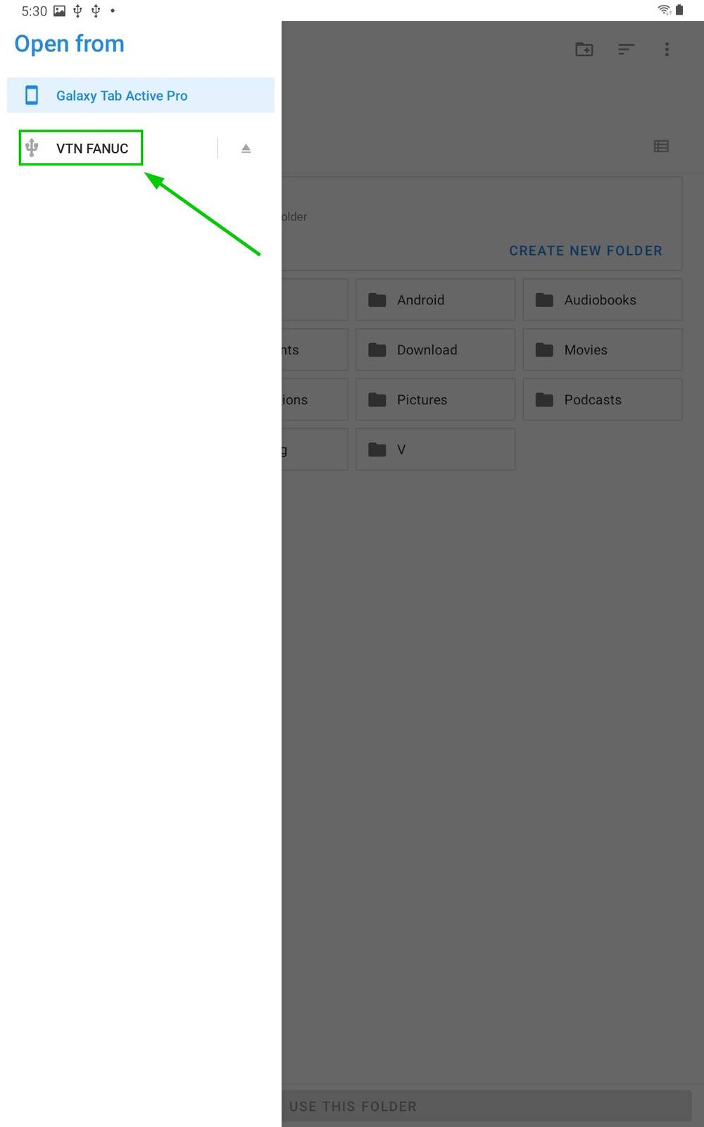
Figure 6: FANUC Teach Pendant USB selection
Click on use this folder.

Figure 7: FANUC Teach Pendant “Use this folder”
Click on “Allow” to access the files.
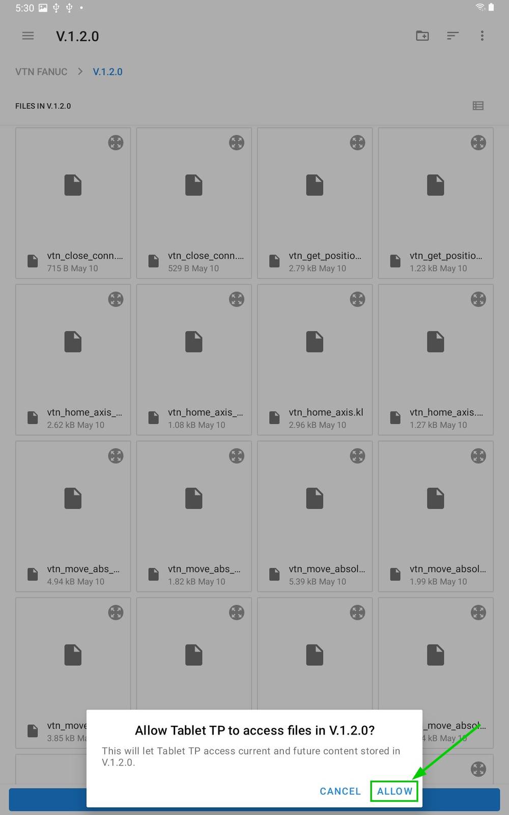
Figure 8: FANUC Teach Pendant “Allow”
Select Yes on the popup.
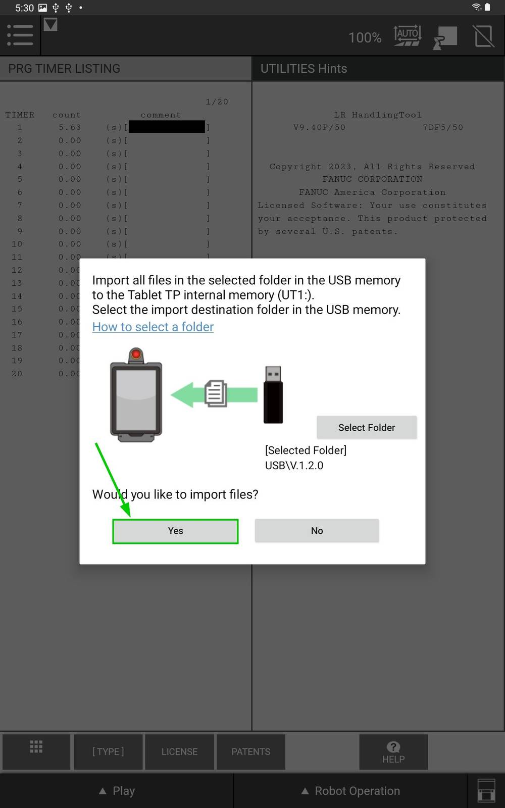
Figure 9: FANUC Teach Pendant confirmation
Load the extension
In the FILE menu on the FANUC pendant click the FILE sub-menu.
Press F5 [UTIL]
Select Set Device
Select USB DISK (UT1:)
Press [DIR] to open the directory subset popup.
Click option Next until you reach the final page containing option Directories.
Select option Directories to open the directory browser.
Select option * PC (all Karel p-code) but do not press ENTER.
Press LOAD to load
V_*programs.Wait for load to complete.
FANUC TCP communication configuration
For additional information: Refer to the FANUC KAREL Reference Manual, section 12, procedure 12.1 for more details on the steps below. This can be accessed via the FANUC Customer Resource Center.
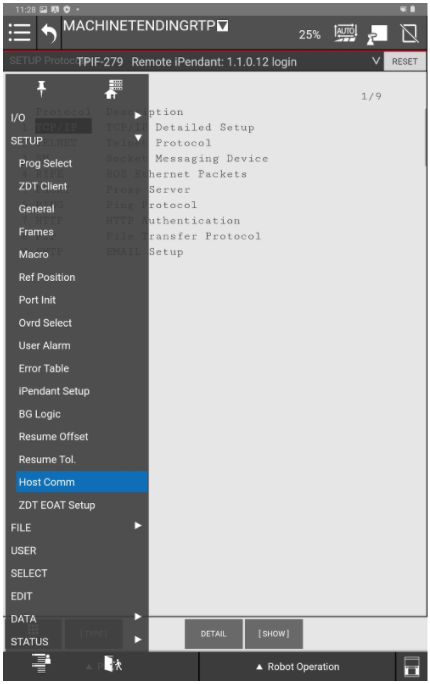
Figure 10: FANUC Teach Pendant Host Comm
Network Configuration
From the FANUC teach pendant use the Legacy menu and navigate to the SETUP section and select Host Comm.
Select TCP/IP.
Press DETAIL.
Configure the FANUC controller’s network settings.
For example, if you used the suggested network configuration with the Robot Safety Module, you should use the following FANUC network configuration:
Port #2 IP addr:: 192.168.5.3
Subnet Mask: 255.255.255.0
Router IP addr: 192.168.5.2
The FANUC controller needs to be rebooted for the network configuration changes to take effect, you can do this at the end of this section.
To ensure it has been configured properly you can select the Router IP addr and press PING.
Client Tag Configuration
Configure the Client Tag network parameters (C1:, C2:, ...).
Due to the FANUC controller’s handling of Client Tags, it is possible that when using a re-configured Client Tag the FANUC controller will refer to old network configuration parameters (IP, Port, etc). To resolve this issue refer to the section in the FANUC controller manual titled “Setting up a Client Tag” or follow the procedure below.
On the FANUC controller teach pendant, press MENU.
Select SETUP.
Select Host Comm.
Press Show.
Select Clients.
Select the Tag you wish to setup for socket messaging and press Detail. You can for example choose C1.
For the Protocol option, ensure that SM (Socket Messaging) is selected.
Move to the Server IP/Hostname option, and type in the IP address of the MachineMotion controller.
If the robot is connected to the “Robot” port of the MachineMotion controller, then the IP address will be “192.168.5.2”.Move to the Remote Port option and edit the value.
In order to edit the value, you will need to open the virtual physical keyboard. Press the icon at the bottom right corner of the pendant screen.
Enter
9999.
Current State has to be set to : STARTED. To achieve this:
Press ACTION and select STOP
Press ACTION and select UNDEFINE
Press ACTION and select DEFINE
Press ACTION and select START.
Move to the Startup State item:
Press CHOICE and select UNDEFINE
Press CHOICE and select DEFINE
Press CHOICE and select START
You may need to reboot the FANUC controller.
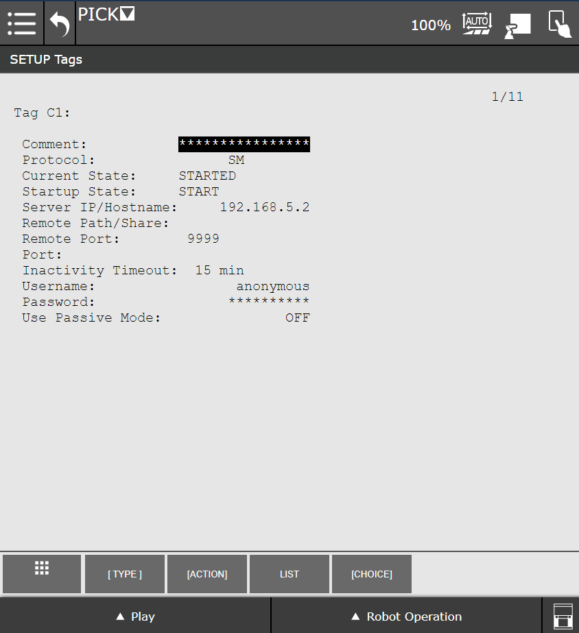
Figure 11: FANUC Teach Pendant Client Tag C1
Using the FANUC Extension
To send commands to the MachineMotion, create a TP program. A TP program is a .TP file containing your instructions (Vention actuator moves, robot moves, call to other programs, etc.) that can be started from the FANUC pendant.
You can create a TP program in several ways:
from your laptop:
Create a
.lsfileUpload it to the FANUC controller via FTP or USB, and it will be compiled to a TP program.
If you have ROBOGUIDE, you can compile your program before sending it to the FANUC controller.You will find usage examples throughout our API documentation.
directly from the FANUC pendant, via its graphical interface:
Refer to the documentation below to enter the arguments of each MachineMotion FANUC extension commands.
The FANUC controller sends commands to the MachineMotion and waits for a response.
The Vention FANUC extension makes use of the FANUC semaphore number 4 for socket communication with the MachineMotion. Please make sure that no other commands or plugins make use of this semaphore number.
.png)
Figure 12: V_MTR_MOVE command in a “CALL” block
.png)
Figure 13: V_MM_CONN_OPEN command in a “Code” block
All of the commands in the FANUC extension should be used with the “CALL” function, except V_MM_CONN_OPEN that must be used with “RUN”.
On version V9.40P/52, the “RUN” function block can show as a “Code” function block.
In both cases, make sure to select the “KAREL” option for Program type.
Then select the desired command for the Program name. All Vention MachineMotion commands start with V_ .
All TP programs sending commands to the MachineMotion should start with calling V_MM_CONFIGURE and V_MM_CONN_OPEN . It is good practice to end a TP program with V_MM_CONN_CLOSE.
If an emergency stop is triggered while running a FANUC TP program calling a MachineMotion command, or if the program is paused or stopped, the command will not be resumed upon restart. You will need to reopen the TCP socket communication with the MachineMotion. As such, it is recommended to go back to the beginning of the program before resuming operation.
FANUC Extension Commands
The following commands provide an interface to control the MachineMotion from within FANUC TP programs.
V_MM_CONFIGURE
Description
This function will set the FANUC Client Tag to be used for the MachineMotion.
This function must be ran before any other actions with a given MachineMotion connection. All TP programs sending commands to the MachineMotion should start with calling V_MM_CONFIGURE and V_MM_CONN_OPEN . It is good practice to end a TP program with V_MM_CONN_CLOSE.
Parameters
Arguments1 : Client Tag
Usage Example
.png)
! Using Client Tag 1
CALL V_MM_CONFIGURE('C1:')
RUN V_MM_CONN_OPEN
CALL V_MM_CONN_CLOSE
V_MM_CONN_OPEN
Description
This function opens the TCP Socket connection with the MachineMotion, and keeps it alive by sending regular heartbeats to the MachineMotion.
This is the only command that must be used with “RUN” instead of “CALL”.
This function must be ran before any other actions with a given MachineMotion connection. All TP programs sending commands to the MachineMotion should start with calling V_MM_CONFIGURE and V_MM_CONN_OPEN . It is good practice to end a TP program with V_MM_CONN_CLOSE.
You will only be able to open the socket connection to the MMAI once per program.
Parameters
None
Usage Example.png)
! Using Client Tag 1
CALL V_MM_CONFIGURE('C1:')
RUN V_MM_CONN_OPEN
CALL V_MM_CONN_CLOSE
V_MM_CONN_CLOSE
Description
This function closes the TCP Socket connection with the MachineMotion.
Upon successfully closing the connection, all axes will stop. The digital input and output states will remain unchanged.
All TP programs sending commands to the MachineMotion should start with calling V_MM_CONFIGURE and V_MM_CONN_OPEN . It is good practice to end a TP program with V_MM_CONN_CLOSE.
Parameters
None
Usage Example
.png)
! Using Client Tag 1
CALL V_MM_CONFIGURE('C1:')
RUN V_MM_CONN_OPEN
CALL V_MM_CONN_CLOSE
V_MM_GET_SAFETY
Description
Query the safety state of the MachineMotion.
This function is not safety rated.
Parameters
Arguments1: Number register, in which to store the safety state.
The safety state of the MachineMotion will be one of those values:
-1corresponds to an error in the safety state0corresponds to no safety state (this would be the case for the MachineMotion AI Robot and MachineMotion AI Robot Pro models)1corresponds to an emergency stop state2corresponds to a normal safety state
Usage Example
.png)
! Using Client Tag 1
CALL V_MM_CONFIGURE('C1:')
RUN V_MM_CONN_OPEN
! Store the safety state in the register number 3
CALL V_MM_GET_SAFETY(3)
CALL V_MM_CONN_CLOSE
V_MM_GET_OP
Description
Query the operational state of the MachineMotion.
Parameters
Arguments1: Number register, in which to store the operational state.
The operational state of the MachineMotion will be one of those values:
1corresponds to operational0corresponds to non-operational
Usage Example
.png)
! Using Client Tag 1
CALL V_MM_CONFIGURE('C1:')
RUN V_MM_CONN_OPEN
CALL V_MM_DISABLE
! Store the operational state in the register number 4
CALL V_MM_GET_OP(4)
CALL V_MM_ENABLE
CALL V_MM_GET_OP(4)
CALL V_MM_CONN_CLOSE
V_MM_ENABLE
Description
Request the MachineMotion to change its operational state to be operational again.
Parameters
None
Usage Example
.png)
! Using Client Tag 1
CALL V_MM_CONFIGURE('C1:')
RUN V_MM_CONN_OPEN
CALL V_MM_DISABLE
! Store the operational state in the register number 4
CALL V_MM_GET_OP(4)
CALL V_MM_ENABLE
CALL V_MM_GET_OP(4)
CALL V_MM_CONN_CLOSE
V_MM_DISABLE
Description
Request the MachineMotion to change its operational state to not be operational.
Parameters
None
Usage Example
.png)
! Using Client Tag 1
CALL V_MM_CONFIGURE('C1:')
RUN V_MM_CONN_OPEN
CALL V_MM_DISABLE
! Store the operational state in the register number 4
CALL V_MM_GET_OP(4)
CALL V_MM_ENABLE
CALL V_MM_GET_OP(4)
CALL V_MM_CONN_CLOSE
V_MTR_MOVE_ASYNC
Description
Moves an axis immediately, to a given position or by a given distance.
This command will not wait for the specified motion to complete. Therefore it is good practice to call V_MTR_WAIT_READY after this command.
Parameters
Arguments1: Desired velocity, in mm/sec
Arguments2: Desired acceleration, in mm/sec2
Arguments3: A boolean indicating whether the motion is relative or absolute:
0corresponds to an absolute move1corresponds to a relative move
Arguments4:
'motor_port;motor_index;target', where:motor_portis the port number the motor is connected tomotor_indexis the index of the motor in the chain of motors (index starts at 1).targetis the desired position for absolute moves, or desired distance for relative moves, in mm.
Each of those values must be separated by
;.Arguments5: (optional) In order to move more than one motor at a time, you can specify additional motors and targets, by repeating the input format of Arguments4, in subsequent Arguments. In that case, all motors will start and stop at the same time.
Usage Example
.png)
! Using Client Tag 1
CALL V_MM_CONFIGURE('C1:')
RUN V_MM_CONN_OPEN
! Move the 2 first motors connected to port 1 by 300mm
CALL V_MTR_MOVE_ASYNC(300, 100, 1, '1;1;300', '1;2;300')
! Wait until the first motor is no longer moving
CALL V_MTR_WAIT_READY('1;1')
CALL V_MM_CONN_CLOSE
V_MTR_MOVE
Description
Moves an axis immediately, to a given position or by a given distance.
This command will wait for the specified motion to complete.
Parameters
Same as V_MTR_MOVE_ASYNC .
Usage Example
.png)
! Using Client Tag 1
CALL V_MM_CONFIGURE('C1:')
RUN V_MM_CONN_OPEN
! Move the first motor on port 1 to 300mm
CALL V_MTR_MOVE(300, 100, 0, '1;1;300')
CALL V_MM_CONN_CLOSE
V_MTR_CONTINUOUS
Description
Moves a conveyor or rotary actuator continuously at a given speed and acceleration.
It is good practice to call V_MTR_WAIT_READY after this command, to wait for the desired velocity to be reached by the actuator.
Parameters
Arguments1: The port number the motor is connected to
Arguments2: The index of the motor in the chain of motors (index starts at 1).
Arguments3: Desired velocity, in mm/sec
Arguments4: Desired acceleration, in mm/sec2
Usage Example
.png)
! Using Client Tag 1
CALL V_MM_CONFIGURE('C1:')
RUN V_MM_CONN_OPEN
! Move the first motor connected to port 1 at a speed of 300mm/sec
CALL V_MTR_CONTINUOUS(1, 1, 300, 100)
CALL V_MTR_WAIT_READY('1;1')
WAIT 10 sec
! Store the velocity of the motor in the register number 6
CALL V_MTR_GET_VEL(6, 1, 1)
! Stop all motors
CALL V_MTR_QUICKSTOP
CALL V_MTR_WAIT_READY('1;1')
CALL V_MM_CONN_CLOSE
V_MTR_ADD_MOVE
Description
Adds a move to list of moves, to be executed later, when the command V_MTR_GO_ASYNC will be sent.
It will enable moving an axis to a given position or distance, later on.
Parameters
Same as V_MTR_MOVE_ASYNC .
Usage Example
.png)
! Using Client Tag 1
CALL V_MM_CONFIGURE('C1:')
RUN V_MM_CONN_OPEN
CALL V_MTR_ADD_MOVE(300, 100, 1, '1;1;300')
CALL V_MTR_ADD_CONTNS(1, 2, 300, 100)
CALL V_MTR_GO_ASYNC
CALL V_MTR_WAIT_READY('1;1')
CALL V_MM_CONN_CLOSE
V_MTR_ADD_CONTNS
Description
Adds a move to list of moves, to be executed later, when the command V_MTR_GO_ASYNC will be sent.
It will enable moving an axis at a given speed, later on.
Parameters
Same as V_MTR_CONTINUOUS .
Usage Example
.png)
! Using Client Tag 1
CALL V_MM_CONFIGURE('C1:')
RUN V_MM_CONN_OPEN
CALL V_MTR_ADD_MOVE(300, 100, 1, '1;1;300')
CALL V_MTR_ADD_CONTNS(1, 2, 300, 100)
CALL V_MTR_GO_ASYNC
CALL V_MTR_WAIT_READY('1;1')
CALL V_MM_CONN_CLOSE
V_MTR_GO_ASYNC
Description
Will start the execution of all the moves that have been queued up by the V_MTR_ADD_MOVE and V_MTR_ADD_CONTNS commands.
This command will not wait for the specified motions to complete. Therefore it is good practice to call V_MTR_WAIT_READY after this command.
Parameters
None
Usage Example
.png)
! Using Client Tag 1
CALL V_MM_CONFIGURE('C1:')
RUN V_MM_CONN_OPEN
CALL V_MTR_ADD_MOVE(300, 100, 1, '1;1;300')
CALL V_MTR_ADD_CONTNS(1, 2, 300, 100)
CALL V_MTR_GO_ASYNC
CALL V_MTR_WAIT_READY('1;1')
CALL V_MM_CONN_CLOSE
V_MTR_CLEAR_LIST
Description
Will clear all the moves that have been queued up by the V_MTR_ADD_MOVE and V_MTR_ADD_CONTNS commands, without executing them.
Parameters
None
Usage Example
.png)
! Using Client Tag 1
CALL V_MM_CONFIGURE('C1:')
RUN V_MM_CONN_OPEN
CALL V_MTR_ADD_MOVE(300, 100, 1, '1;1;999')
CALL V_MTR_CLEAR_LIST
CALL V_MTR_ADD_MOVE(300, 100, 1, '1;1;300')
CALL V_MTR_GO_ASYNC
CALL V_MTR_WAIT_READY('1;1')
CALL V_MM_CONN_CLOSE
V_MTR_HOME
Description
Moves an axis immediately, towards its home position, until its home sensor is triggered. The command will wait for the motion to complete, and will reset the zero position of the axis. This is a calibration move.
Parameters
Arguments1:
'motor_port;motor_index', where:motor_portis the port number the motor is connected tomotor_indexis the index of the motor in the chain of motors (index starts at 1).
Each of those values must be separated by
;.
Usage Example
.png)
! Using Client Tag 1
CALL V_MM_CONFIGURE('C1:')
RUN V_MM_CONN_OPEN
CALL V_MTR_HOME('1;1')
CALL V_MM_CONN_CLOSE
V_MTR_QUICKSTOP
Description
Immediately stops motion on given axes.
This command will not wait for the specified axes to completely stop. Therefore it is good practice to call V_MTR_WAIT_READY after this command.
Parameters
Arguments1: (optional)
'motor_port;motor_index', where:motor_portis the port number the motor is connected tomotor_indexis the index of the motor in the chain of motors (index starts at 1).
Each of those values must be separated by
;.If the Arguments2 is unspecified, then all connected motors will stop.
Arguments2: (optional) In order to stop more than one motor at a time, you can specify additional motors, by repeating the input format of Arguments1, in subsequent Arguments.
Usage Example
.png)
! Using Client Tag 1
CALL V_MM_CONFIGURE('C1:')
RUN V_MM_CONN_OPEN
! Move the first motor connected to port 1 at a speed of 300mm/sec
CALL V_MTR_CONTINUOUS(1, 1, 300, 100)
WAIT 10 sec
! Store the velocity of the motor in the register number 6
CALL V_MTR_GET_VEL(6, 1, 1)
! Stop all motors
CALL V_MTR_QUICKSTOP
CALL V_MTR_WAIT_READY('1;1')
CALL V_MM_CONN_CLOSE
V_MTR_WAIT_READY
Description
Waits for a motor to have reached its target, and be ready to accept new motion commands.
Generally, motion is allowed when target is reached and when operation is enabled.
A motor is considered to have reached its target if any of these are satisfied:
it has reached its specified position or velocity for trapezoidal and continuous moves respectively
it has triggered one of its end of travel sensors
it has been interrupted by a quick stop command.
Parameters
Arguments1:
'motor_port;motor_index', where:motor_portis the port number the motor is connected tomotor_indexis the index of the motor in the chain of motors (index starts at 1).Each of those values must be separated by
;.
Arguments2: (optional) In order to wait for more than one motor at a time, you can specify additional motors by repeating the input format of Arguments1, in subsequent Arguments.
Usage Example
.png)
! Using Client Tag 1
CALL V_MM_CONFIGURE('C1:')
RUN V_MM_CONN_OPEN
! Move the 2 first motors connected to port 1 by 300mm
CALL V_MTR_MOVE_ASYNC(300, 100, 1, '1;1;300', '1;2;300')
! Wait until the 2 motors are no longer moving
CALL V_MTR_WAIT_READY('1;1', '1;2')
CALL V_MM_CONN_CLOSE
V_MTR_SET_POS
Description
Sets the current position of an axis to a new value. It does not move the axis.
Parameters
Arguments1: The port number the motor is connected to
Arguments2: The index of the motor in the chain of motors (index starts at 1).
Arguments3: The new position value, in mm.
Usage Example
.png)
! Using Client Tag 1
CALL V_MM_CONFIGURE('C1:')
RUN V_MM_CONN_OPEN
! Set the position of the first motor connected to port 1 to 0mm
CALL V_MTR_SET_POS(1, 1, 0)
! Store the position of the first motor connected to port 1 in the register number 20
CALL V_MTR_GET_POS(20, 1, 1)
CALL V_MM_CONN_CLOSE
V_MTR_GET_POS
Description
Queries the current position of a motor.
Parameters
Arguments1: Number register in which to store the current position of the motor.
It will be a real number corresponding to the position of the axis, in millimetres.Arguments2: The port number the motor is connected to
Arguments3: The index of the motor in the chain of motors (index starts at 1).
Usage Example
.png)
! Using Client Tag 1
CALL V_MM_CONFIGURE('C1:')
RUN V_MM_CONN_OPEN
CALL V_MTR_SET_POS(1, 1, 0)
! Move the first motor connected to port 1 at a speed of 300mm/sec
CALL V_MTR_CONTINUOUS(1, 1, 300, 100)
LBL[1:read]
! Store the current position of the motor connected to port 1 in the register number 7
CALL V_MTR_GET_POS(7, 1, 1)
! If the motor has travelled more than 100mm, then finish the program
IF R[7] < 100, JMP LBL[1]
CALL V_MM_CONN_CLOSE
V_MTR_GET_VEL
Description
Queries the current speed of a motor.
Parameters
Arguments1: Number register in which to store the current velocity of the motor.
It will be a real number corresponding to the speed of the axis, in mm/sec.Positive numbers correspond to moving in the positive direction of the axis.
Negative numbers correspond to moving in the negative direction of the axis.
Arguments2: The port number the motor is connected to
Arguments3: The index of the motor in the chain of motors (index starts at 1).
Usage Example
.png)
! Using Client Tag 1
CALL V_MM_CONFIGURE('C1:')
RUN V_MM_CONN_OPEN
! Move the first motor connected to port 1 at a speed of 300mm/sec
CALL V_MTR_CONTINUOUS(1, 1, 300, 100)
WAIT 10 sec
! Store the velocity of the motor in the register number 6
CALL V_MTR_GET_VEL(6, 1, 1)
! Stop all motors
CALL V_MTR_QUICKSTOP
CALL V_MTR_WAIT_READY('1;1')
CALL V_MM_CONN_CLOSE
V_MTR_GET_READY
Description
Queries whether or not a motor has yet reached its target, and is ready to accept new motion commands.
Generally, motion is allowed when target is reached and when operation is enabled.
A motor is considered to have reached its target if any of these are satisfied:
it has reached its specified position or velocity for trapezoidal and continuous moves respectively
it has triggered one of its end of travel sensors
it has been interrupted by a quick stop command.
Parameters
Arguments1: Number register in which to store the current readiness of the motor.
0corresponds to the target not yet being reached, or the motor not being ready to accept new motion commands.1corresponds to the target having been reached and the motor being ready to accept new motion commands.
Arguments2: The port number the motor is connected to
Arguments3: The index of the motor in the chain of motors (index starts at 1).
Usage Example
.png)
! Using Client Tag 1
CALL V_MM_CONFIGURE('C1:')
RUN V_MM_CONN_OPEN
! Move the 2 first motors connected to port 1 by 300mm
CALL V_MTR_MOVE_ASYNC(300, 100, 1, '1;1;300', '1;2;300')
! Wait until the first motor is no longer moving
LBL[1:wait]
R[5] = 1
CALL V_MTR_GET_READY(5, 1, 1)
IF R[5] = 0, JMP LBL[1]
CALL V_MM_CONN_CLOSE
V_MTR_GET_BRAKE
Description
Queries whether or not the brake is locked on a given motor.
Parameters
Arguments1: Number register in which to store the current state of the motor brake.
0corresponds to the brake being unlocked.1corresponds to the brake being locked.
Arguments2: The port number the motor is connected to
Arguments3: The index of the motor in the chain of motors (index starts at 1).
Usage Example
.png)
! Using Client Tag 1
CALL V_MM_CONFIGURE('C1:')
RUN V_MM_CONN_OPEN
! Store the brake state in the register number 14
CALL V_MTR_GET_BRAKE(14, 1, 1)
CALL V_MM_CONN_CLOSE
V_MTR_GET_HOME
Description
Queries whether or not the home sensor of a given motor is triggered.
Parameters
Arguments1: Number register in which to store the current state of the motor’s home sensor.
0corresponds to the home sensor not being triggered.1corresponds to the home sensor being triggered.
Arguments2: The port number the motor is connected to
Arguments3: The index of the motor in the chain of motors (index starts at 1).
Usage Example
.png)
! Using Client Tag 1
CALL V_MM_CONFIGURE('C1:')
RUN V_MM_CONN_OPEN
! Move the first motor on port 1 to very far away in the negative direction
CALL V_MTR_MOVE(300, 100, 1, '1;1;-999999')
! Store the state of the home sensor in register number 10
CALL V_MTR_GET_HOME(10, 1, 1)
CALL V_MM_CONN_CLOSE
V_MTR_GET_END
Description
Queries whether or not the endstop sensor of a given motor is triggered.
Parameters
Arguments1: Number register in which to store the current state of the motor’s endstop sensor.
0corresponds to the endstop sensor not being triggered.1corresponds to the endstop sensor being triggered.
Arguments2: The port number the motor is connected to
Arguments3: The index of the motor in the chain of motors (index starts at 1).
Usage Example
.png)
! Using Client Tag 1
CALL V_MM_CONFIGURE('C1:')
RUN V_MM_CONN_OPEN
! Move the first motor on port 1 to very far away in the positive direction
CALL V_MTR_MOVE(300, 100, 1, '1;1;999999')
! Store the state of the end sensor in register number 11
CALL V_MTR_GET_END(11, 1, 1)
CALL V_MM_CONN_CLOSE
V_IO_GET_IN
Description
Reads the digital input values from a Digital IO Module or a Push Button Module, (0 or 1), and places them in a FANUC numerical register.
You can read either the value of given input pin, or the values of all the input pins on a given module.
Parameters
Arguments1: Number register in which to store the current state of the digital input(s) of a given module.
If Arguments4 is specified, it will store the value of a single pin.
A pin can have a value of0or1.If Argument4 is unspecified, it will store the value of all the pins of the module.
They will be represented as a byte. For example,15corresponds to0b1111, meaning that all 4 input pins of the module currently have a value of1.
Arguments2: The “Control” port number the module is connected to
Arguments3: The module’s address (device ID)
Arguments4: (optional) the input pin number to read on the module.
If Arguments4 is specified, the register specified at Arguments1 will store the value of a single pin.
If Arguments4 is unspecified, the register specified at Arguments1 will store the value of all the input pins of the module.
Usage Example
.png)
! Using Client Tag 1
CALL V_MM_CONFIGURE('C1:')
RUN V_MM_CONN_OPEN
CALL V_IO_GET_IN(11, 1, 1)
CALL V_IO_GET_IN(12, 1, 1, 1)
CALL V_IO_SET_OUT(1, 1, 0, 0)
CALL V_IO_GET_OUT(13, 1, 1)
CALL V_IO_GET_OUT(14, 1, 1, 0)
CALL V_MM_CONN_CLOSE
V_IO_GET_OUT
Description
Reads a digital outputs from a Digital IO Module or a Power Switch Module, (0 or 1), and places them in a FANUC numerical register.
You can read either the value of given output pin, or the values of all the output pins on a given module.
Parameters
Arguments1: Number register in which to store the current state of the digital output(s) of a given module.
If Arguments4 is specified, it will store the value of a single pin.
A pin can have a value of0or1.If Arguments4 is unspecified, it will store the value of all the pins of the module.
They will be represented as a byte. For example,15corresponds to0b1111, meaning that all 4 output pins of the module currently have a value of1.
Arguments2: The “Control” port number the module is connected to
Arguments3: The module’s address (device ID)
Arguments4: (optional) the output pin number to read on the module.
If Arguments4 is specified, the register specified at Arguments1 will store the value of a single pin.
If Arguments4 is unspecified, the register specified at Arguments1 will store the value of all the output pins of the module.
Usage Example
.png)
! Using Client Tag 1
CALL V_MM_CONFIGURE('C1:')
RUN V_MM_CONN_OPEN
CALL V_IO_GET_IN(11, 1, 1)
CALL V_IO_GET_IN(12, 1, 1, 1)
CALL V_IO_SET_OUT(1, 1, 0, 0)
CALL V_IO_GET_OUT(13, 1, 1)
CALL V_IO_GET_OUT(14, 1, 1, 0)
CALL V_MM_CONN_CLOSE
V_IO_SET_OUT
Description
Writes a digital output pin on a Digital IO Module or a Power Switch Module.
Parameters
Arguments1: The “Control” port number the module is connected to
Arguments2: The module’s address (device ID)
Arguments3: The output pin number to write on the module
Arguments4: The value to write to the pin.
Value can be either0or1.
Usage Example
.png)
! Using Client Tag 1
CALL V_MM_CONFIGURE('C1:')
RUN V_MM_CONN_OPEN
CALL V_IO_GET_IN(11, 1, 1)
CALL V_IO_GET_IN(12, 1, 1, 1)
CALL V_IO_SET_OUT(1, 1, 0, 0)
CALL V_IO_GET_OUT(13, 1, 1)
CALL V_IO_GET_OUT(14, 1, 1, 0)
CALL V_MM_CONN_CLOSE
V_IO_GET_USR_IN
Description
Reads the value of a retained mqtt topic on the MachineMotion corresponding to a custom user input, and places it in a FANUC String register.
Parameters
Arguments1: String register in which to store the current value of the user input topic.
It will correspond to the retained message of the mqtt topictsapi/userInput/<CUSTOMINPUT>, where<CUSTOMINPUT>represents the string inputted as Arguments2.Arguments2: The user input mqtt topic name.
Usage Example
.png)
! Using Client Tag 1
CALL V_MM_CONFIGURE('C1:')
RUN V_MM_CONN_OPEN
CALL V_IO_GET_USR_IN(2, 'TEST_IN')
CALL V_IO_SET_USR_OUT('TEST_OUT', 'CUSTOM_MESSAGE')
CALL V_IO_GET_USR_OUT(3, 'TEST_OUT')
CALL V_MM_CONN_CLOSE
V_IO_GET_USR_OUT
Description
Reads the value of a retained mqtt topic on the MachineMotion corresponding to a custom user output, and places it in a FANUC String register.
Parameters
Arguments1: String register in which to store the current value of the user output topic.
It will correspond to the retained message of the mqtt topictsapi/userOutput/<CUSTOMOUTPUT>, where<CUSTOMOUTPUT>represents the string inputted as Arguments2.Arguments2: The user output mqtt topic name.
Usage Example
.png)
! Using Client Tag 1
CALL V_MM_CONFIGURE('C1:')
RUN V_MM_CONN_OPEN
CALL V_IO_GET_USR_IN(2, 'TEST_IN')
CALL V_IO_SET_USR_OUT('TEST_OUT', 'CUSTOM_MESSAGE')
CALL V_IO_GET_USR_OUT(3, 'TEST_OUT')
CALL V_MM_CONN_CLOSE
V_IO_SET_USR_OUT
Description
Writes the value of a retained mqtt topic on the MachineMotion corresponding to a custom user output.
Parameters
Arguments1: The user output mqtt topic name.
It will correspond to the mqtt topic
tsapi/userOutput/<CUSTOMOUTPUT>, where<CUSTOMOUTPUT>represents the string inputted as Arguments1.Arguments2: The retained mqtt message string to publish on the user output topic corresponding to Arguments2.
Usage Example
.png)
! Using Client Tag 1
CALL V_MM_CONFIGURE('C1:')
RUN V_MM_CONN_OPEN
CALL V_IO_GET_USR_IN(2, 'TEST_IN')
CALL V_IO_SET_USR_OUT('TEST_OUT', 'CUSTOM_MESSAGE')
CALL V_IO_GET_USR_OUT(3, 'TEST_OUT')
CALL V_MM_CONN_CLOSE
V_SEND_RAW
Description
For advanced functionalities, the FANUC extension can send commands directly to the TCP Socket API interface of the MachineMotion.
It will store the response in a FANUC String register.
To know more about the TCP Socket API interface, please see TCP Socket API for MachineMotion documentation.
Parameters
Arguments1: String register in which to store the response from the TCP Socket API.
Arguments2: String to be sent to the TCP Socket API.
Arguments3: (optional) If you need to send a longer string to the TCP Socket API, you can use multiple Arguments parameters. Each String has a maximum size of 34 characters. All Arguments parameters will be concatenated in one string, sent as one request to the TCP Socket API.
Usage Example
.png)
! Using Client Tag 1
CALL V_MM_CONFIGURE('C1:')
RUN V_MM_CONN_OPEN
CALL V_SEND_RAW(1, 'getTorque_1,1')
CALL V_MM_CONN_CLOSE
It is good practice to call V_MTR_WAIT_READY after these commands:
V_MTR_MOVE_ASYNCto wait for the motion to completeV_MTR_CONTINUOUSto wait for the desired velocity to be reachedV_MTR_GO_ASYNCto wait for the motion to completeV_MTR_QUICKSTOPto wait for the motion to haltV_SEND_RAW, depending on the usage
If you call the following commands while a motor is not ready to accept new commands, the FANUC extension will generate an error :
V_MTR_MOVEV_MTR_MOVE_ASYNCV_MTR_CONTINUOUSV_MTR_GO_ASYNCV_MTR_HOMEV_MTR_QUICKSTOPV_MTR_SET_POSV_SEND_RAW (maybe), depending on the usage
Debugging and viewing V_ log messages
Errors generated by the FANUC extension will follow the following structure:
ROUT-042andROUT-043Means the parameters are not supported. Please verify that your inputs match the documentation.You can view these errors in the “Menu/ALARM/System Log” and “Menu/ALARM/Alarm Log”
APSH-097is en error generated by the MachineMotion. The description associated to the error should give more details about the situation.You can view these errors in the “Menu/ALARM/Appl Log”
In troubleshooting situations it may be useful to examine internal program logs from the V_* KAREL programs. To do so, perform the following procedure to access the FANUC controller USER log area.
On the FANUC controller teach pendant, press MENU.
Select User
A list of log messages from previously run programs will appear.
If the program is erroring at the V_MM_CONN_OPEN block, here are things you can check :
Is your ethernet cable plugged in? Unplug it and replug it to make sure.
Are the network settings setup correctly? Make sure you configured the correct FANUC Ethernet port in the Host Comm menu. If both ports are on the same subnet, it can create conflicts, consider changing the unused one to a different subnet.