Overview
Installing actuators and linear guides accurately is crucial to ensuring these components, and your overall assembly, will perform well for a long time. Accuracy is even more important when mounting two actuators, guides, or a combination of them in parallel.
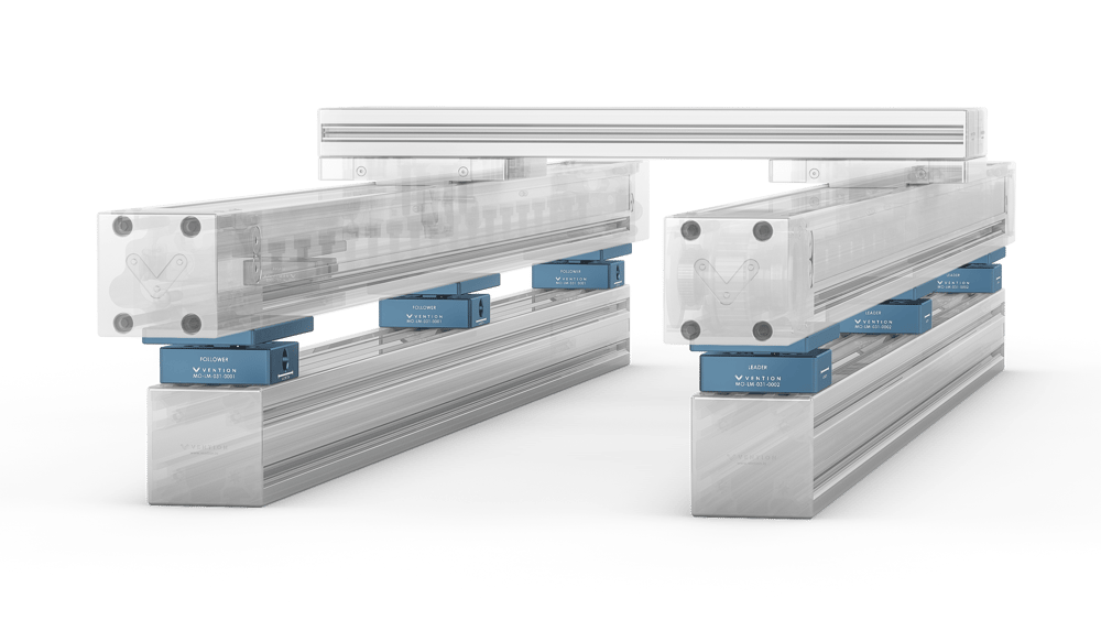 Figure 1: Two enclosed actuators mounted in parallel using the self aligning mounts. |
Enclosed actuators and guides have a highly rigid design, so they must be installed according to strict requirements. Installing two linear profile guide rails, for instance, requires precision ground surfaces and highly accurate installation tools.
However, Vention gets around this requirement for the enclosed actuators and guides by incorporating a self-aligning compliance system that lets you install two guides or actuators in parallel using only a measuring tape. This is both easier for you and better for the system’s longevity.
Composition and Function
Vention self-aligning mounts allow enough degrees of freedom that no internal stress develops in the bearings, even if the axes are out of alignment by a few millimeters.
The mounts come in two configurations: follower and leader. Follower mounts (part number MO-LM-031-0001, Figure 2) contain a spherical bearing that allows for three rotational degrees of freedom, as well as a shaft and bushing system for one translational degree of freedom.
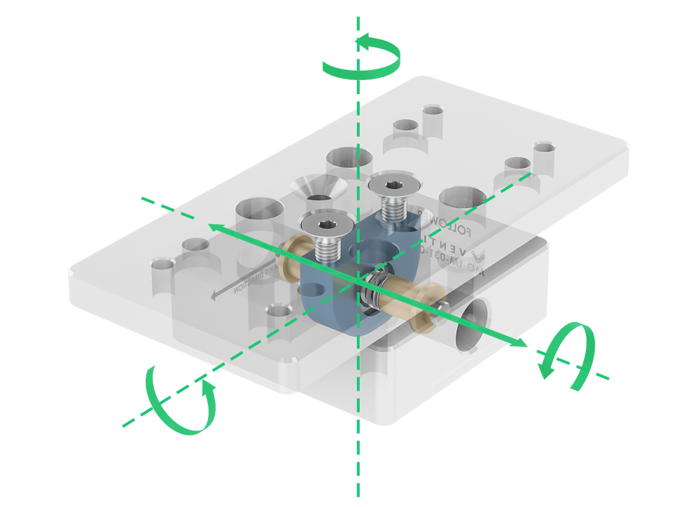 Figure 2: Self-aligning follower mount, with degrees of freedom (three rotational and one translational) indicated by solid green arrows. |
Leader mounts (part number MO-LM-031-0002, Figure 3) also contain a spherical bearing, but no shaft and bushing system—so they have the same three rotational degrees of freedom as the follower mounts, but no translational degree of freedom.
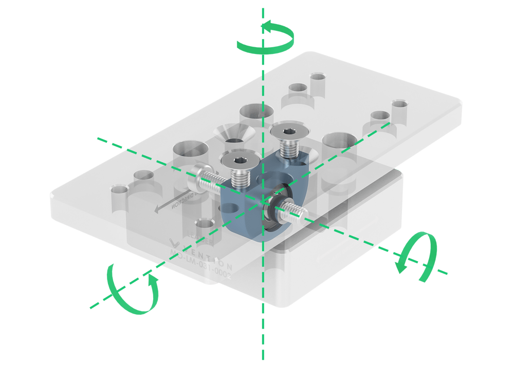 Figure 3: Self-aligning leader mount, with degrees of freedom (three rotational) indicated by solid green arrows. Note that there is no translational degree of freedom. |
If two parallel actuators were mounted with all leaders or all followers, they wouldn’t have the correct degrees of freedom, resulting in a “floppy” or over-constrained assembly. However, when one actuator is mounted with leader mounts, and the other with follower mounts—and both actuators are connected via a common gantry system—the rotational and translational degrees of freedom combine to create a fully constrained yet flexible system.
That’s why Vention actuators and guides can be mounted with only a measuring tape: the flexible system compensates for any misalignments.
In the case of horizontal misalignment, for example, the follower mount’s horizontal translation compensates for the angular misalignment (ϴ) between the actuators (Figure 4).
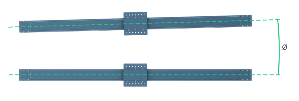 Figure 4: ϴ represents the angular misalignment from horizontal. |
In other words, the follower mount allows one actuator to move slightly closer to or further from the leader-mounted actuator, as needed.
The Vention self-aligning system also compensates for vertical misalignment, shown in Figure 5.
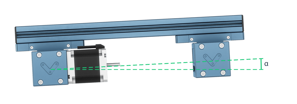 Figure 5: α represents the angular misalignment from vertical. |
The mounting blocks allow the actuators to tilt together, which prevents the stresses that would be induced if the actuators were misaligned and mounted directly on an extrusion.
Technical Specifications
The table below indicates how much misalignment—in terms of mm and degrees from a parallel position—the mounts can compensate for.
Follower Mount | Leader Mount | |
|---|---|---|
Part Number | MO-LM-031-0001 | MO-LM-031-0002 |
Translational freedom (mm) | ±3 | ±N/A |
Rotational freedom (degrees) | ±6.5 | ±6.5 |
Load Capacity (Kg) | 275 | 275 |
Installation
To attach the self-aligning mounts to the machine frame (extrusion), use four counterbores (Figure 6, in blue).
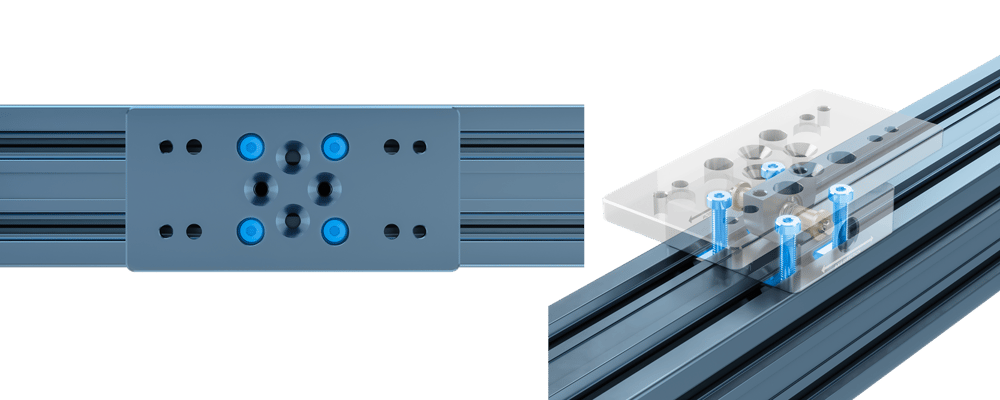 Figure 6: Install fasteners in these counterbores (highlighted in blue) to attach the self-aligning mount to the extrusion frame. |
The fasteners can be passed through the top plate, or the top plate can be removed for installation.
To attach the self-aligning mounts to the actuator, there are two possible configurations, shown in Figure 7.
⚠️ Important: The Axis Direction arrow on the bottom half of the mount must be aligned with the actuator’s travel direction.
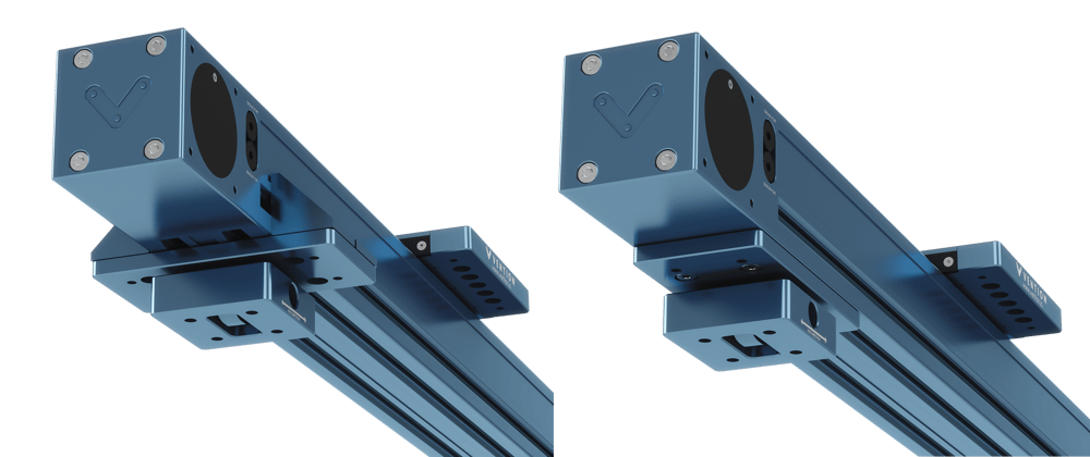 Figure 7: Possible mount orientations for connection to the actuator. Left: Attached to the actuator via ST-GP-003-0001 standard gussets. Right: Attached directly to the actuator via the t-slots on the actuator’s underside. |
To attach via standard gussets (Figure 7, left): Attach the top plate of the mount to the bearing housing through the countersink holes shown in Figure 8.
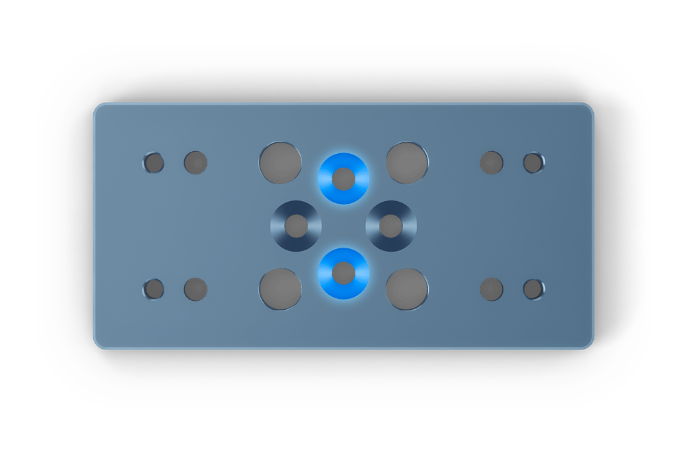 Figure 8: Countersinks (highlighted in blue) for attaching the mount via standard gussets. |
Attach the top plate of the mount to the actuator through Vention’s standard gussets, ST-GP-003-0001.
To attach via the actuator’s t-slots (Figure 7, right): Connect the top plate of the mount to the actuator through the countersink holes shown in Figure 9.
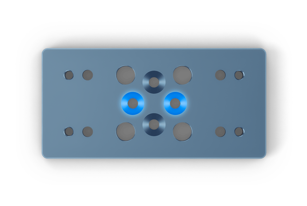 Figure 9: Countersinks (highlighted in blue) for attaching the mount via the actuator’s t-slots. |
Install the top plate directly on the actuator underside using M8 fasteners and t-nuts, and tighten with an L-key.
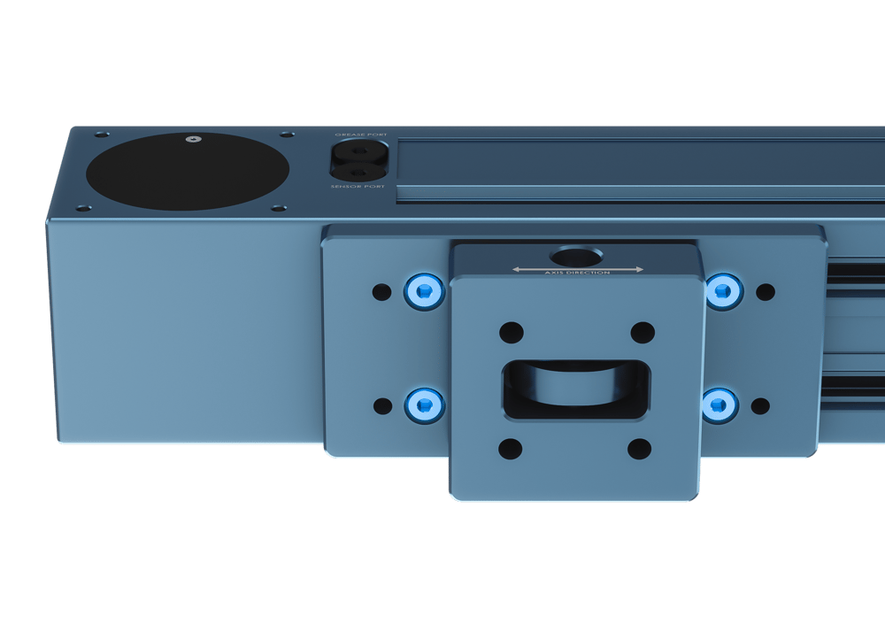 Figure 10: Close-up view of the mount attached directly to the actuator via t-slots. |
Tip: To ensure stability, we recommend installing one mount per meter (approximately) for enclosed guides or actuators.
Finally, remember to use only one type of mount per actuator. One actuator must be attached exclusively to leader mounts (MO-LM-031-0002), while the other must have only follower mounts (MO-LM-031-0001).