|
Overview
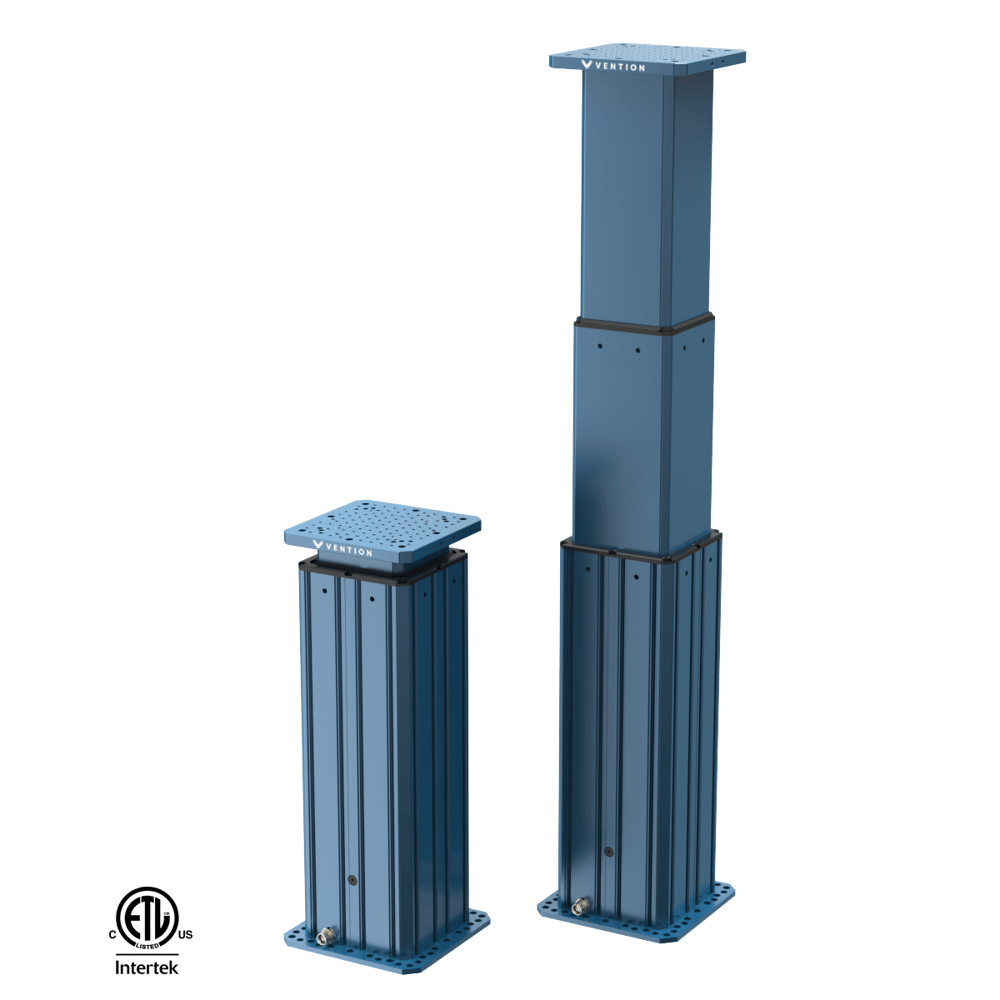
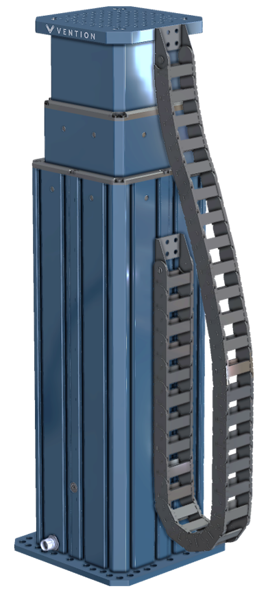
The telescopic lift column is a rigid, high force column designed for heavy duty applications. This fully enclosed column has no pinch points and requires minimal maintenance.
The column is guided by high performance polymer bushings and the motion assembly is comprised of 2 lead screws which are joined together by a belt drive system and driven by Vention’s standard 156mm NEMA 34 Stepper Servo Motor. The efficiency of the actuator is tuned to ensure a self-locking system for usage with cobots while minimizing friction and energy loss.
The motor, sensors and drive components are all pre-installed inside the lift column, leaving only the mounting of the column to the ground or frame, the robot atop the column, and connecting the column to the MachineMotion controller the only steps to be fully deployed.
The lift column’s base extrusion is equipped with T-slots to enable mounting of accessories and controllers, such as MachineMotion or pneumatic controls.
This document covers requirements for current version of MachineMotion controller. For previous version, refer to link below:
Disclaimers:
The T-slots are not intended to be used as structural mounts and therefore should not be used for any load bearing applications.
The telescopic column is only compatible with MachineMotion controllers.
Precise mechanical synchronization of multiple telescopic columns is not possible and they must be used as individual units
The telescopic column is intended for upright operation only. It is not intended to be used horizontally or upside down.
Applications
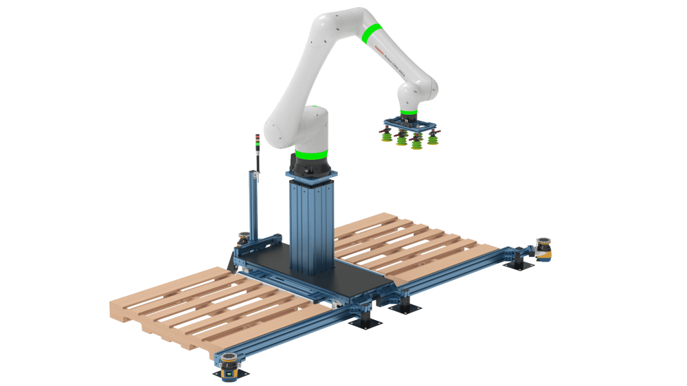
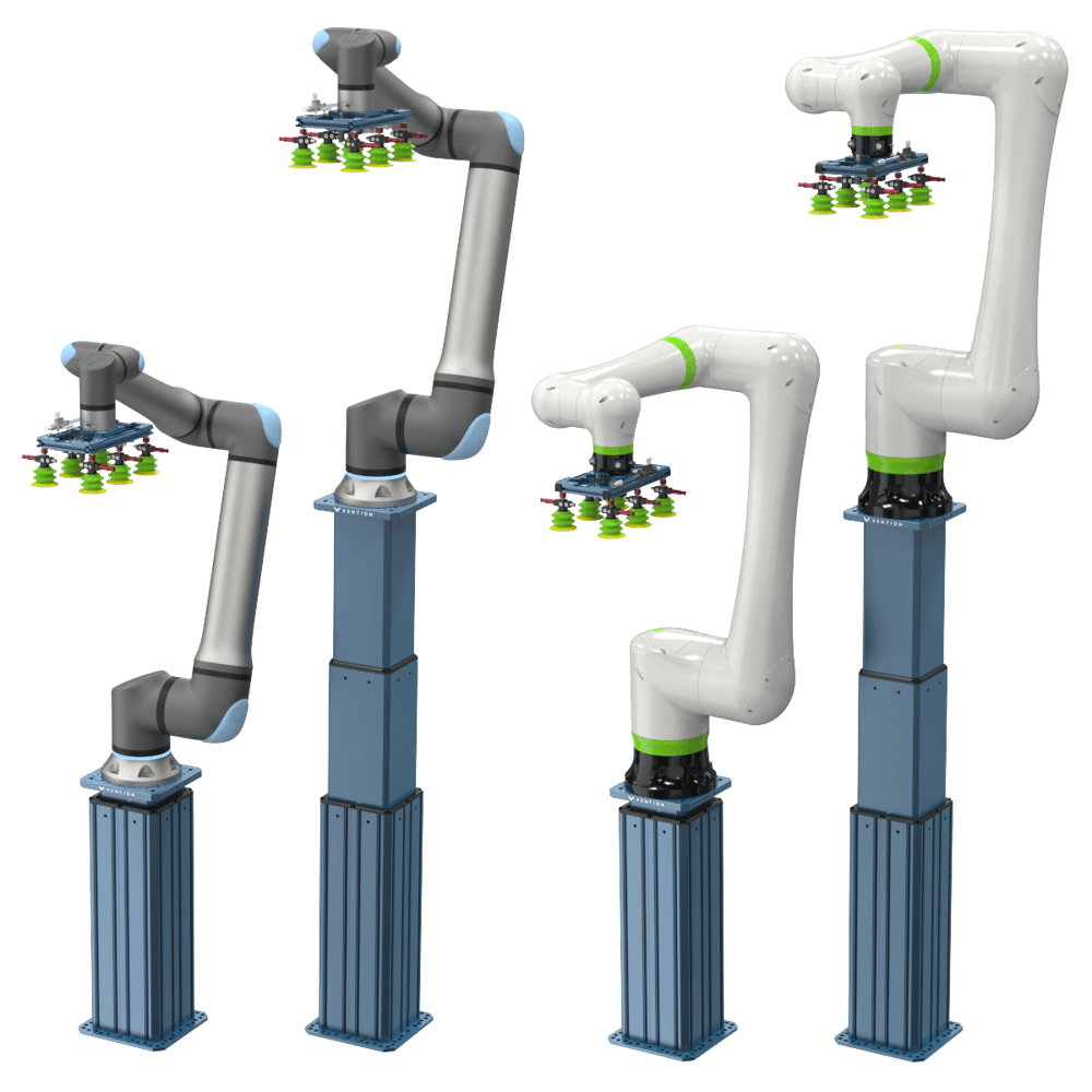
The Telescopic Lift Column can be used in a variety of applications, offering a simpler design to complex range extenders at higher payloads. The column is designed to support cobots with payloads of up to 25kg including the Doosan H Series, UR Cobots, as well as the Fanuc CRX Series.
Cobot palletizers
|
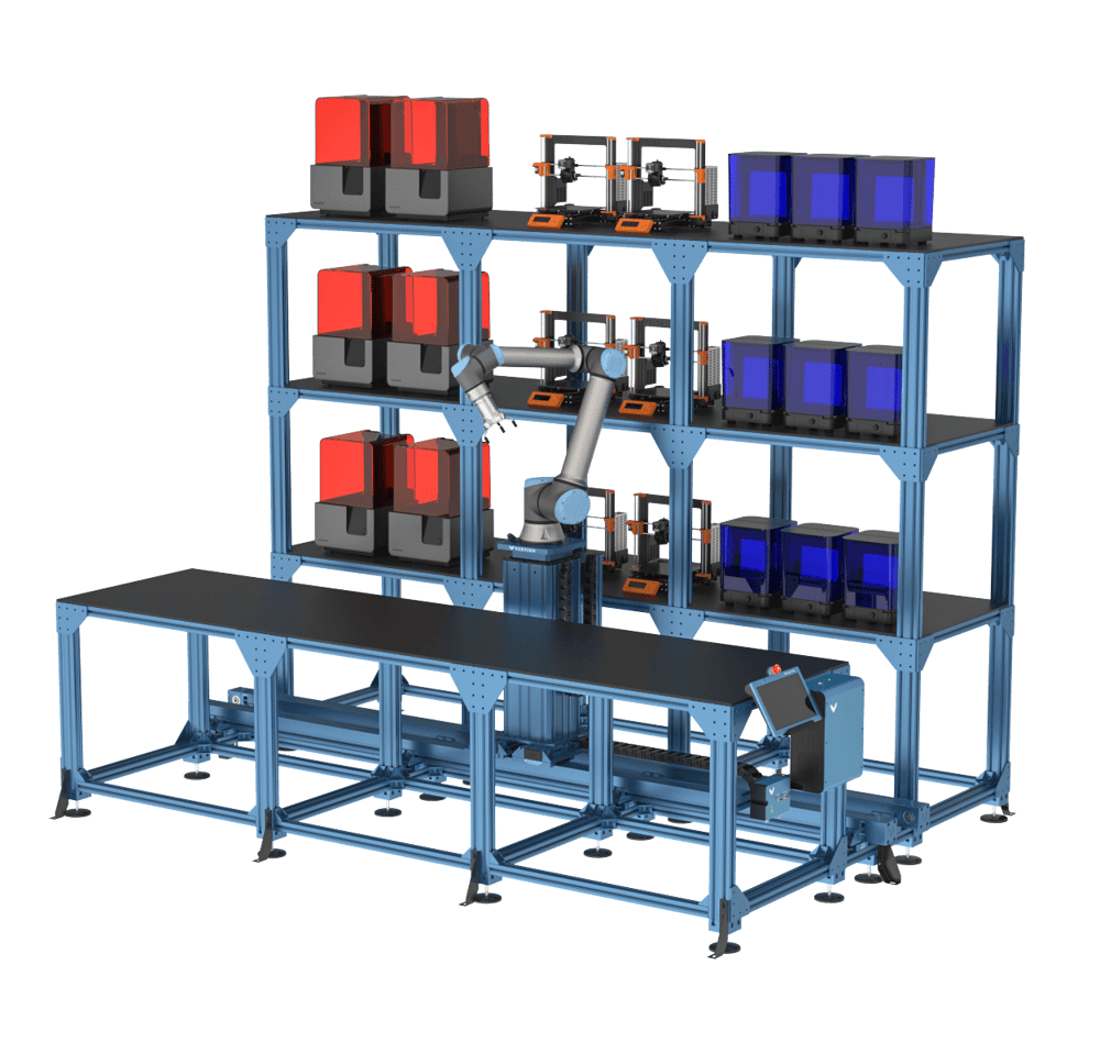
Robot Cells
|
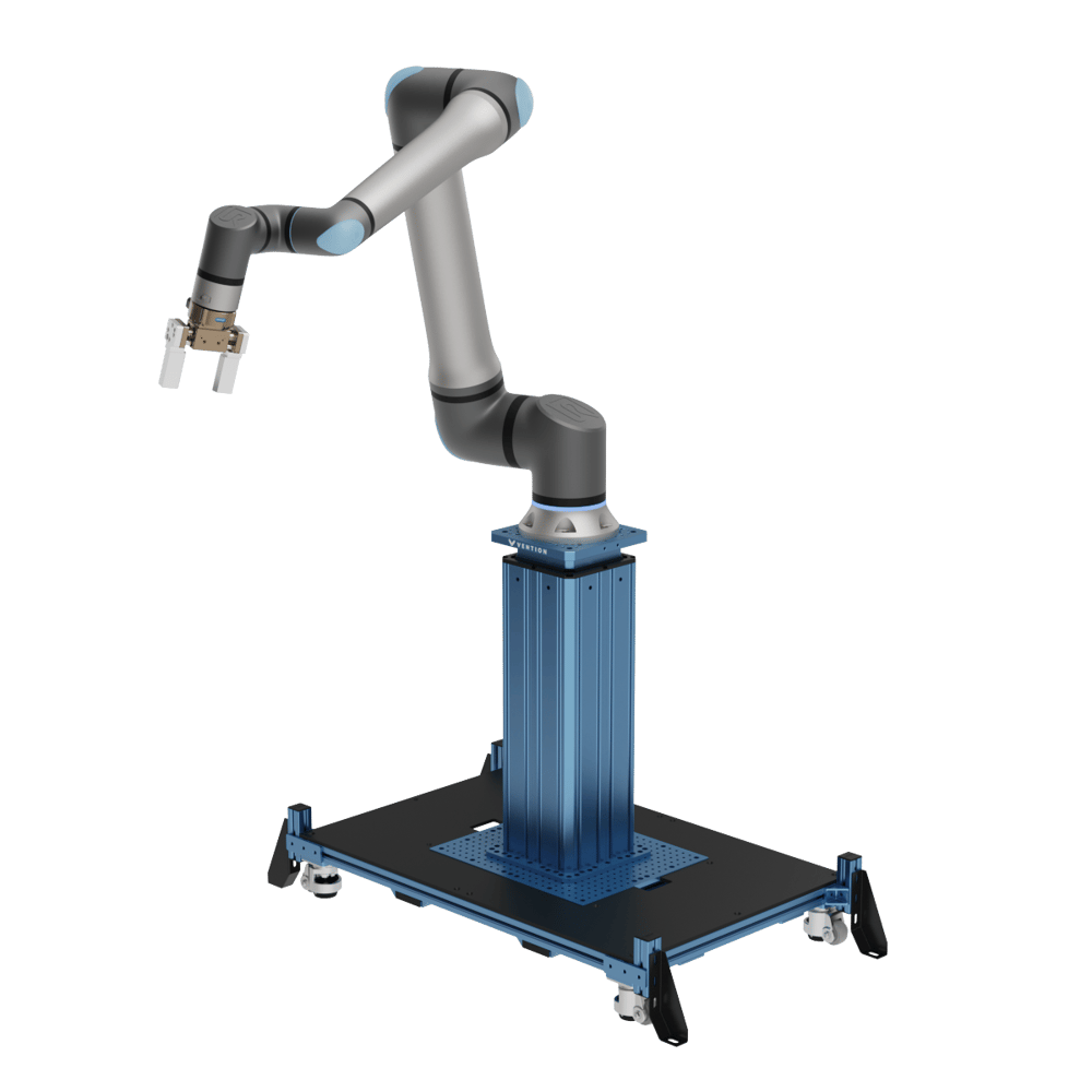
Pick and Place
|
Explore more public designs to get ideas on how you could use the telescopic lift column.
Robot Compatibility
|
The telescopic lift is designed to natively support the following robots using the indicated bolt patterns:
Doosan
H2017, Pattern A
H2515, Pattern A
M0609, Pattern B
M0617, Pattern B
M1013, Pattern B
M1509, Pattern B
Epson T6, Pattern A
Fanuc
CRX-10, Pattern B
CRX-20, Pattern B
CRX-25, Pattern D*
Universal Robots
UR10e, Pattern B
UR16e, Pattern B
UR20, Pattern C*
|
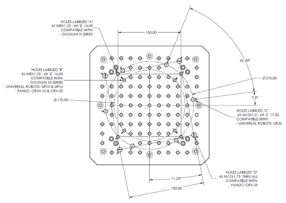
Note: * The mounting angle of the CRX-25 is clocked at 11.25 degrees. The UR20 is also clocked at 7.5 degrees. If you would like to mount these robots orthogonally, see the supported robot plate below.
With use of robot plates the list of compatible robots is expanded to include:
Robot Supported | Vention Plate Part Number |
|---|---|
Aubo i5 | |
Aubo i10 | |
Doosan H2017 or H2515 | |
Doosan M0609, M0617, M1013, or M1509 | |
Epson G3 | |
Epson T3 | |
Epson T6 | |
Fanuc CRX-5 | |
Fanuc CRX-10 | ST-RB-100-0225 or ST-RB-001-0008 or ST-RB-100-0315 or ST-RB-100-0180 |
Fanuc CRX-20 | |
Fanuc CRX-25 | |
Fanuc SR-3iA | |
Fanuc SR-6iA | |
Fanuc SR-12iA | |
Franka Emika | |
Kuka LRB iiwa 7 R800 | |
Kuka LRB iiwa 14 R820 | |
Omron TM5 | |
Universal Robots UR3 | ST-RB-100-0225 or ST-RB-001-0005 or ST-RB-100-0180 or ST-RB-100-0180 |
Universal Robots UR5 | ST-RB-100-0225 or ST-RB-001-0003 or ST-RB-001-0002 or ST-RB-100-0180 |
Universal Robots UR10 | ST-RB-100-0225 or ST-RB-001-0008 or ST-RB-100-0315 or ST-RB-100-0180 |
Universal Robots UR16 | ST-RB-100-0225 or ST-RB-001-0008 or ST-RB-100-0315 or ST-RB-100-0180 |
Universal Robots UR20 | |
Universal Robots UR30 |
Specific Robot Limitations
All of the robots listed above are supported by the telescopic lift column, however some robots may have some limitations to ensure compatibility with the lift column.
In general it is recommended to move the telescopic lift while the robot is retracted or partially retracted. Do not operate the telescopic lift while the robot arm is fully extended.
Simultaneous motion of the robot arm and the column is not supported.
CRX-25
The CRX-25’s large reach can cause very large bending moments, up to 1200Nm during standard operation. Because of this it is recommended to keep the Telescopic Lift below a travel position of 670mm or a total height from the base of 1500mm. Extending beyond this point will lead to accelerated wear and noticeable deflection as the robot moves. Additionally, the robot should be retracted as much as possible while the Telescopic Lift is in motion because of the limitation of 700Nm bending moment during motion.
UR20
The UR20’s large reach can cause very large bending moments, over 1000Nm during standard operation. Because of this it is recommended to keep the Telescopic Lift below a travel position of 700mm or a total height from the base of 1530mm. Extending beyond this point will lead to accelerated wear and noticeable deflection as the robot moves. Additionally, the robot should be retracted as much as possible while the Telescopic Lift is in motion because of the limitation of 700Nm bending moment during motion.
Technical Specifications
Accuracy from Homed Position | +/- 0.5 mm |
Back Drive Resistance | Self Locking |
Standard Payload | 100 kg |
Max Payload** | 225 kg |
Max Speed (No Payload) | Up to 100 mm/s |
Nominal Speed | 75 mm/s |
Weight | 56.54 kg |
Footprint | 315 mm x 315 mm |
Compressed height*** | 830 mm |
Extended height*** | 1700 mm |
Total Travel | 870 mm |
Displacement ratio | 8.381 |
Motor Compatibility | Integrated NEMA 34, 14-mm shaft with a 5-mm key |
Sensor Compatibility | Integrated sensor: M18 Inductive Proximity Sensor |
Note: **Operating at the maximum lifting capacity will reduce the permissible duty cycle.
***The home position and extended position can vary by ± 2mm among different columns.
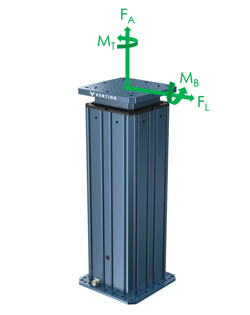
Load Capacity
The table and figure below describe the maximum loads and moments in each direction during operation when the column is either stationary or moving. Continued operation at these maximum values will have an impact on product life.
|
Description | Value |
|---|---|
Axial force (Fa) | See Drive Forces |
Max Dynamic twist moment (Mt) *** | 700 Nm |
Max Static twist moment (Mt) **** | 1700 Nm |
Max Dynamic lateral force (Fl) *** | 575 N |
Max Static lateral force (Fl) **** | 1300 N |
Nominal bending moment (Mb) | 350 Nm |
Max Dynamic bending moment (Mb) *** | 700 Nm |
Max Static bending moment (Mb) **** | 1900 Nm |
***Note: Maximum dynamic loads represent the highest loads that can be applied to the top plate of the telescopic lift while motion is still possible. Life will be affected by how often the column is operated at the max bending moment as well as position in stroke. The more extended the lift column is the more stress is applied to the guiding and driving systems, reducing life. Note that simultaneous motion of the robot arm and the column is not permitted.
*****Note: Maximum static loads represent the highest possible loads applied to the telescopic lift column. At these loads, motion will not be possible and going beyond these values could lead to damage or failure of the lift column. These values must be respected during robot E-stop events.
Driving Force and Speed
The driving force indicates how much weight the actuator can move and how quickly it can accelerate. This force is shown as “Fa”, or axial force, in the Load Capacity figure. The speed and lifting capacity of the Telescopic Lift Column are dependent on multiple variables with the major two being applied moment and extension position. The speed and lifting capacity of the column decrease as a moment is applied due to added frictional losses between guiding systems. Additionally when a moment is present the extension of the column brings the guiding bearings closer together which increases the friction generated as well.
Note that the graph below represents an idealized situation where no bending moment is applied to the column.
|
.png)
For some examples of more typical applications the following graph shows how the column can be expected to behave during lifting operations depending on different robots and use cases. Note that in all cases retracting speed can be run at a maximum of 100mm/s.
|
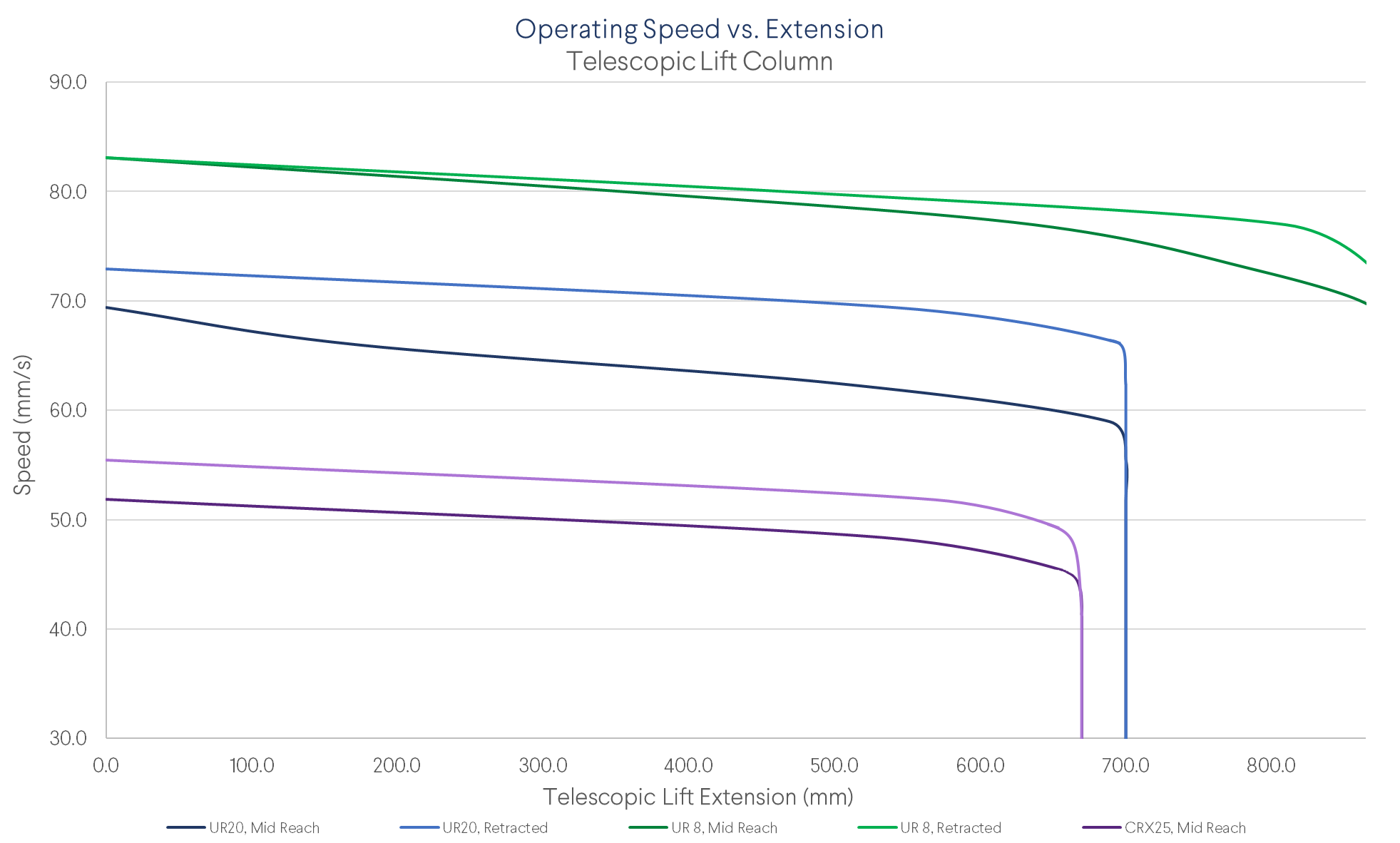
The situations shown in the graph represent the following load cases:
Doosan H2017 at full payload with an extension that generates a constant 400 Nm bending moment
Doosan H2017 at full payload at a retracted position such that the bending moment is 200 Nm
UR 16 at full payload with an extension that generates a constant 285 Nm bending moment
UR 16 at full payload at a retracted position such that the bending moment is 100 Nm
CRX25 at full payload with a mid extension that generates a constant 450 Nm bending moment. Note the full stroke of the lift column is not possible with the robot extended.
CRX25 at full payload at a retracted position such that the bending moment is 250 Nm
For assistance in calculating the expected travel speeds of the lift column for please contact our application engineering specialists.
Duty Cycle
The duty cycle of the telescopic actuator is 10% when being used with a 100kg payload and travel speeds of 40-50mm/s and alternating moment loads from 0 to 700 Nm. The meaning of 10% duty cycle is such that in a 1 hour period the lift column would operate in evenly spaced spurts for a total of 6 minutes within the hour.
Exceeding this 10% duty cycle can cause heat build up and lead to increased wear and reduction in life of components and grease.
Reducing load, moment, and/or speed can increase the duty cycle.
For assistance in knowing if your application will respect the duty cycle or questions about the life of the lift column, please contact our application engineering specialists.
Electrical Specifications
Below the motor specifications as well as the connector pinout are provided:
Property | Value |
|---|---|
Number of phases | 2 |
Number of steps | 200 |
Step angle | 1.8° |
Rated voltage | 2.4VDC |
Rated max. current | 10A |
Phase resistance | 0.24Ω ± 0.1 (20°C) |
Phase inductance | 2.9mH ± 20% (1kHz 1V RMS) |
Connector pin number | Wire group/gauge | Wire color | Function |
|---|---|---|---|
1 | Signal/24AWG | White | Incremental encoder Z+ output (5V TTL) |
2 | Signal/24AWG | Yellow | Incremental encoder B- output (5V TTL) |
3 | Signal/24AWG | Green | Incremental encoder B+ output (5V TTL) |
4 | Signal/24AWG | Pink | Incremental encoder A- output (5V TTL) |
5 | Signal/24AWG | Gray | Incremental encoder A+ output (5V TTL) |
6 | Motor/18AWG | Black | Stepper Phase B- input |
7 | Motor/18AWG | Blue | Stepper Phase B+ input |
8 | Motor/18AWG | White | Stepper Phase A- input |
9 | Motor/18AWG | Brown | Stepper Phase A+ input |
10 | Auxiliary/24AWG | Blue | 0V input (100mA) |
11 | Auxiliary/24AWG | Brown | 24V input (100mA) |
12 | Signal/24AWG | Purple | Incremental encoder Z- output (5V TTL) |
13 | Signal/24AWG | Blue | End Sensor B output (24V normally closed) |
14 | Signal/24AWG | Black | End Sensor A output (24V normally closed) |
15 | Signal/24AWG | Orange | Reserved/Do not connect |
16 | Signal/24AWG | Red | Reserved/Do not connect |
17 | Auxiliary/24AWG | Black | Brake input (24V unlocked, 750mA) |
Assembly Instructions
The telescopic lift column comes completely pre-assembled, with its integrated motor and sensors. All you need to do is connect it to a MachineMotion controller. The telescopic column can be mounted in one of two ways:
Directly to the floor using our floor anchoring solution. For instructions and requirements see ST-RB-033-0002.
Use a Vention frame and/or plate with appropriate ballast. Contact our application engineers for help determining the required ballast for your application. The base of the telescopic column should be attached to the extrusion frame or ballast using the twelve included M8 X 1.25 X 18mm fasteners torqued to 13-15Nm.
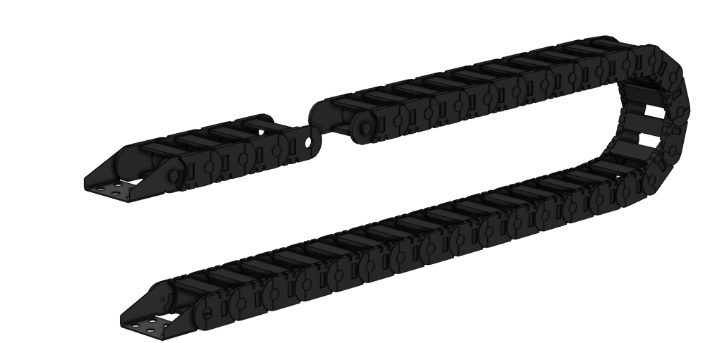
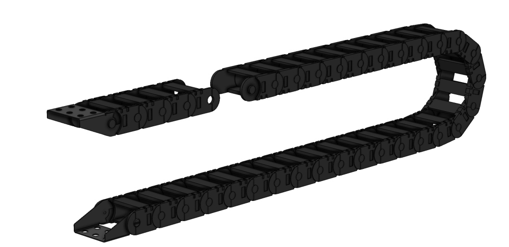
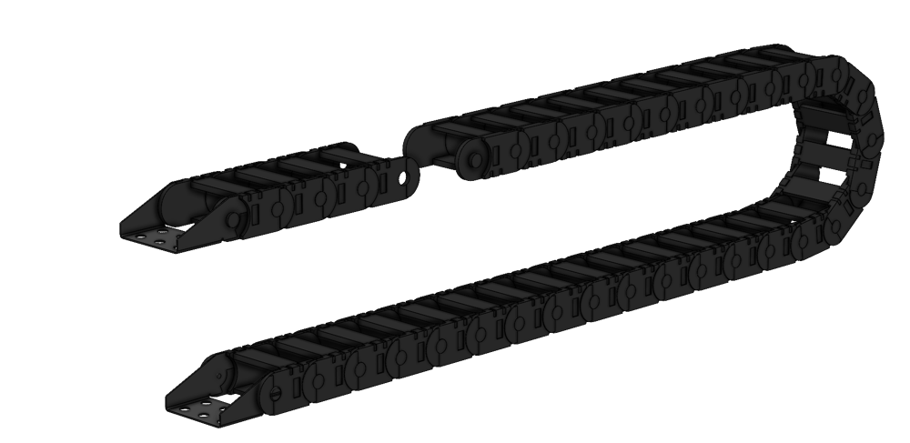
To attach a drag chain to the telescopic lift column, use MO-DC-002-1485 and follow these instructions:
Detach the first 5 links from the rest of the drag chain.
Flip the section of 5 links upside down so that they bend in the opposite direction as the rest of the chain.
The drag chain end must also be flipped so that it is in the same orientation as the unmodified end.
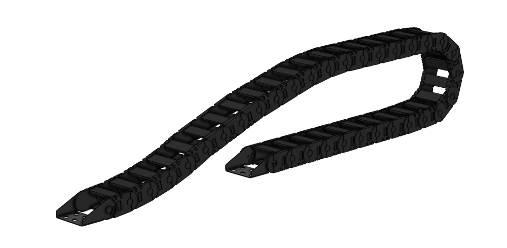
Reattach the 5 links to the rest of the drag chain. The chain should now be able to be arranged into the following shape.
Attach the drag chain to the telescopic lift column by screwing the end with the modified links to the telescopic lift top plate. The unmodified side of the drag chain should be connected to the top third of the main extrusion of the telescopic lift column.
The top plate of the telescopic lift column has holes for mounting the drag chain on two sides. If you wish to install the drag chain on another side, simply remove the top plate by undoing the eight M6 fasteners and rotate the plate by 90 degrees. Reinstall the telescopic lift top plate and attach the drag chain to the side of your choice.
Maintenance
For maintenance instructions please refer to the appropriate section in our Maintenance Technical Document.