Welcome to the technical documentation for programming your Vention Machine in Python. This document is designed to guide you through the essential steps and best practices for leveraging the full potential of our API within MachineLogic’s integrated web development environment. In this documentation, you will learn how to access the web editor, configure your machine and create Python applications.
Whether you are a seasoned developer or new to our platform, this guide provides a comprehensive resource for creating scalable automation applications within Vention’s platform. Vention’s python API can
This document is intended to be used by technicians and engineers with some level of familiarity with Python programming and software development.
2. Accessing MachineLogic
To access MachineLogic, your MachineBuilder design must contain:
A MachineMotionAI Controller
One of the following component types:
once a controlled devices have been added to a design, their Configuration properties will be shown in the configuration pane:
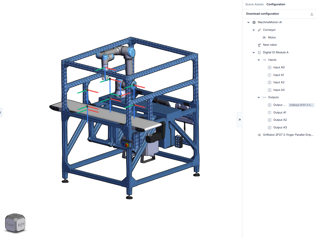
Figure 1: The Configuration pane
The configuration data is automatically populated once the corresponding device has been added to the design. For more information on each device’s configuration properties, select one of the links below:
Once the automation components have been added to the design, access MachineLogic by selecting the MachineLogic tab at the top of the MachineBuilder toolbar:
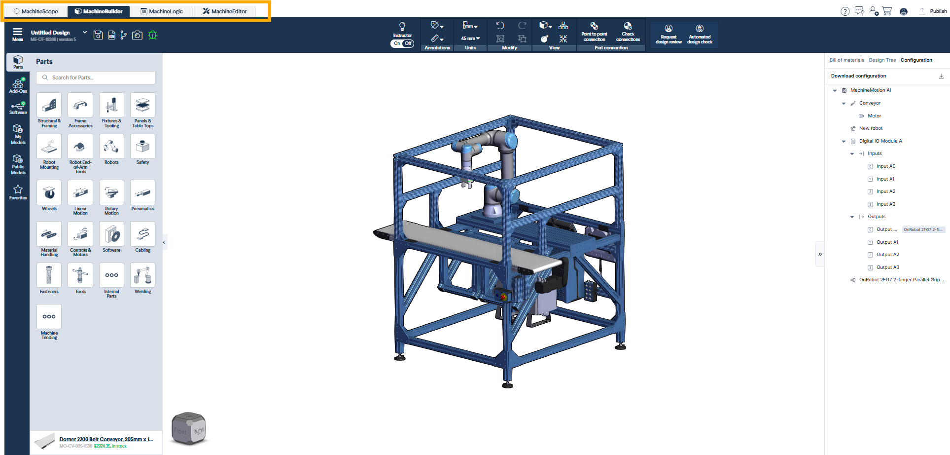
Figure 2: Accessing MachineLogic
To create a new application, select the New app button from the landing page:
.png)
Figure 3: Creating a new application from the MachineLogic landing page
3. Programming your application from MachineLogic’s Python Editor
To create a new Python application, begin by selecting the New App button from the MachineLogic landing page to access the MachineLogic Python editor.
The User Interfaces feature a cloud implementation of VS Code. to learn more about its functionalities and features, consult the VS Code documentation here
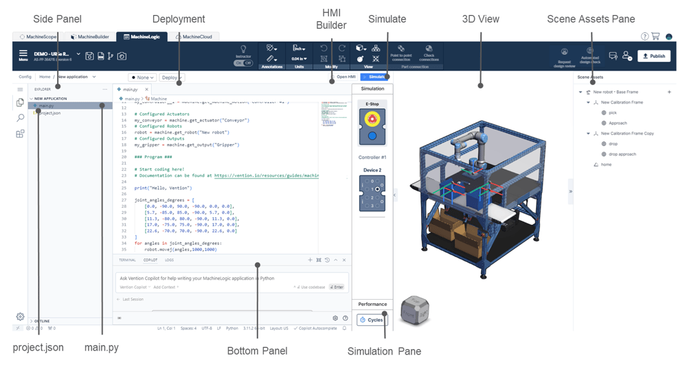 Figure 4: MachineLogic Python Editor |
Every new Python application contains two files by default, main.py and project.json
3.1. Side Panel
the collapsible side panel is used to display either the Explorer, Search or Extension functions. The Explorer is displayed by default.
Explorer
The Explorer is used to create files and directories contained in an application. it is possible to upload files and directories by Drag and Dropping content directly over the Side Panel
Search
Use Search to quickly query the application to find or replace code snippets.
Extensions
Extensions are provided by the VS Code community and allow access to additional functionalities that can be installed to the current application.
3.2. Deployment
The deployment buttons are used to access One-Click-Deploy functionalities. to learn more about deployment of your application, click here
3.3. HMI Builder
HMI Builder is a feature that can be used to create Operator Interfaces that allow interaction with the application.
to learn more about HMI builder, click here.
3.3. Simulate
Use this button to launch or interrupt the simulation
3.4. 3D View
This view displays the current loaded design and enables the MachineBuilder context menu.
Conveyor box Mechanics can also be enabled when Conveyors are present in the design.
To enable Conveyor Simulation, select the plus icon on the associated conveyor and specify the desired simulated behavior.
3.5. Scene Assets Pane
The scene Assets pane is where robot programming Assets are displayed. To learn more about Scene Assets and how to use them to generate robot motion, click here
3.6. Simulation Panel
Device Emulation:
The simulation panel allows for the emulation of IO devices and push buttons added to the design.
When these devices are configured, they will show in the simulation pane and allow interactions with the program and application when the simulation is running.
Emulation is supported for the following devices:
PushButton module
Digital I/O module
Estop Module
Estop Module W/ reset
Cycle Time
The Cycle time functionality displays both cycle time and cycle count when playing a program in simulation.
To calculate cycle time, the application must contain both a MachineAnalytics Cycle Start and Cycle End events. Both commands are found in the Set Output Category.
.png) Figure 6: Cycle Time Display |
3.7. Bottom Panel
The bottom panel is used to access the Terminal, the **Vention Copilot **tool or the Process Logs.
Terminal:
A fully integrated terminal that starts at the root of your workspace and enables working in the shell of your choice without leaving the editor
Copilot
Copilot enables AI assistance for programming your application using Vention’s Python API. Once a prompt has been entered, code snippet can be directly incorporated in the application. Use Copilot to speed up your development time and learning curve when programming with Vention’s Python API
Tip: For best results when using the copilot tool, add the pre-populated configuration code supplied by default in your code editor to your prompts. This will ensure that Copilot is aware of your configured actuator and their friendly names when suggesting code snippets. See section 3.9 for more information about the configuration.
Logs
The logs display information about running processes and provide error reporting and debugging help.
3.8. main.py
this file will be executed by default when launching your application. This is where most of the control code for your application should be written. This file is pre-populated with initialization code so you can start programming your application as soon as the application is created.
Here is an example of the initialization code for a new application containing a robot, conveyor and a digital output:
from machinelogic import Machine, ActuatorGroup
        from machinelogic import MachineException, MachineMotionException, ActuatorGroupException, ActuatorException, RobotException, DigitalOutputException

        ### Configuration ###

        # The following code has been automatically generated from the configuration.
        # If the configuration changes, please update the code below, and ensure that the names match.

        machine = Machine()

        scene = machine.get_scene()

        my_controller__1 = machine.get_machine_motion("Controller #1")

        # Configured Actuators
        my_conveyor = machine.get_actuator("Conveyor")
        # Configured Robots
        robot = machine.get_robot("New robot")
        # Configured Outputs
        my_gripper = machine.get_output("Gripper")

        ### Prgram ###

        # Start coding here!
        # Documentation can be found at /technicaldocumentation/docs/

        print("Hello, Vention")
Notice how the content of the configuration is automatically populated in the main.py file using commands from the API:
# Configured Actuators
        my_conveyor = machine.get_actuator("Conveyor")
        # Configured Robots
        robot = machine.get_robot("New robot")
        # Configured Outputs
        my_gripper = machine.get_output("Gripper")
Tip: These commands use the friendly names as defined in the configuration page, any changes made to the configuration prior to the creation of the app will have to be manually added to the main.py file afterwards.
Using a single main.py file as the entry point for simulation is the most straightforward way to simulate your python application from the web environment using Vention’s Python API. However, specifying additional simulation entry points is possible by configurating the project.json file
3.9. project.json
Using the project.json, file you can specify what bash commands you want to run when playing the application. This makes it possible to launch multiple processes simultaneously as specified in the project.json file, enabling enabling the creation of more scalable and modular Python apps. Complex applications can be broken down into different processes running in parallel.
By default, the project.json file specifies the main.py file as the single entry point:
{
        "processes": {
        "onPlay": [
        {
        "name": "MachineCode App","command": "python3 -u main.py"
        }
        ]
        }
        }
Tip: Adding the -u command line option when running python scripts allow for the stdout and stderr streams to be unbuffered, allowing for proper log output in the “LOGS” tab
to specify additional processes, add them to the project.json file as shown in the example below:
{
        "processes": {
        "onPlay": [
        { "name": "Process 1", "command": "python3 -u Process 1.py" },
        { "name": "Process 2", "command": "python3 -u Process 2.py" },
        { "name": "Server process", "command": "node web_server.js", "port": 3020 },
        ]
        }
        }
Notice how the example above also contains the port number when launching a web server process. In the example below, pressing the play button will simultaneously launch Process 1.py, Process 2.py and web_server.js.
For access to python applications example, click here
4. Adding external Python Modules to your development environment
If your application requires special python packages, create a requirements.txt file in your application and list all required modules. The proper machine-logic-sdk version compatible with your MachineMotion controller should also be specified in the requirements.txt file.
When the Simulate button is clicked, a separate process will run to create and activate venv for all packages specified.