Overview
The mechanical assembly checklist should be used as a final check once the system is assembled.
Use the following checks to ensure that your system is assembled correctly.
General assembly
1. Extrusions | Extrusions are assembled according to CAD design.
| |
2. Gussets | High-precision (HP) and general-precision (GP) gussets are installed in correct locations. | |
3. Plates | Assembly plates are properly mounted; no fasteners are missing. | |
4. Frame | Base frame can support more than enough weight.
For details, see the assembly guide . |
|
5. Screws | Screws are securely tightened.
For details, see the anti-vibration products guide . | |
6. Level | System is leveled.
| |
7. Cables and tubes | Cables and tubes are sufficiently long and run along clear paths.
For details, see the cable management guide . | |
8. Hinges | Hinges move smoothly. | |
9. Safety interlock | Safety interlocks are adjusted and fully engaged. | |
10. Custom parts | Custom parts are deburred and have no sharp edges. |
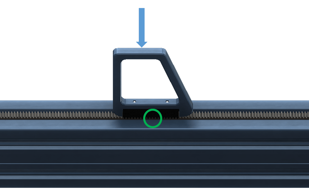
Rack and pinion
11. Rack spacing | Gear rack sections are properly joined.
For details, see the rack and pinion actuator guide . |
|
12. End-stop brackets | End sensor brackets are tightened on rack. | |
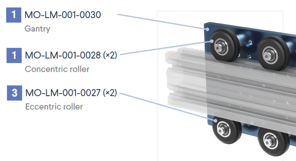
13. Housing | Bearings and/or rollers are securely mounted on housing. |
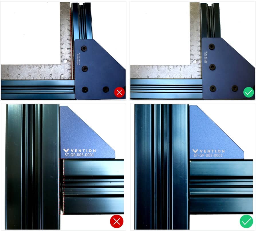
Alignment
14. Rails |
| |
15. Shaft | If system has butt-jointed rails: Butt-joints have no chamfer, gaps, or misalignment.
| |
16. Roller wheels | Eccentric rollers are all on one side and properly adjusted; concentric rollers are all on the opposite side. |
Lubrication and maintenance
Find step-by-step instructions for these components in the maintenance guide.
17. Linear ball bearings | Installation: Ball bearings lubricated. |
|
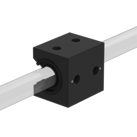
18. Plain bearings | Installation (recommended): Shaft cleaned with 3-in-1 oil. |
|
19. Ball screws | Installation: Ball screws lubricated. |
|
20. Rack and pinion | Installation: Gear racks lubricated. |
|
21. Enclosed timing belt actuator | Installation: N/A (ships pre-lubricated). |
|
22. Rotary actuator | Installation: N/A (ships pre-lubricated). |
|
.jpg)
.jpg)
.jpg)
.png)
.png)
Sensors
23. End-stop sensor | If using an actuator: End-stop sensors are functioning (to detect when gantry reaches end of travel). |
24. End-stop bumper | Sensor has sufficient clearance from plate at end-stop position.
|
25. Sensor mounting | Sensors have enough clearance and are not intercepted by the movement of other components. |
Motors
26. Motor | Before installation: Shaft has key installed on it. |
27. Power transmission devices | Before installation: Design follows proper order of motor, gearbox, and brake. |