|
.png)
Overview
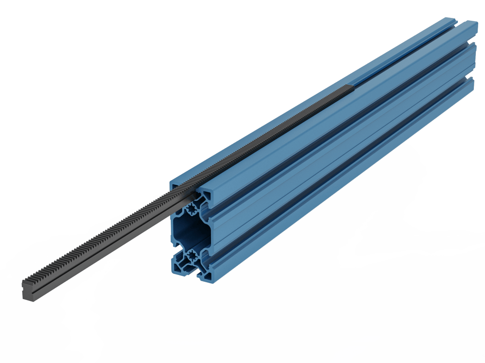
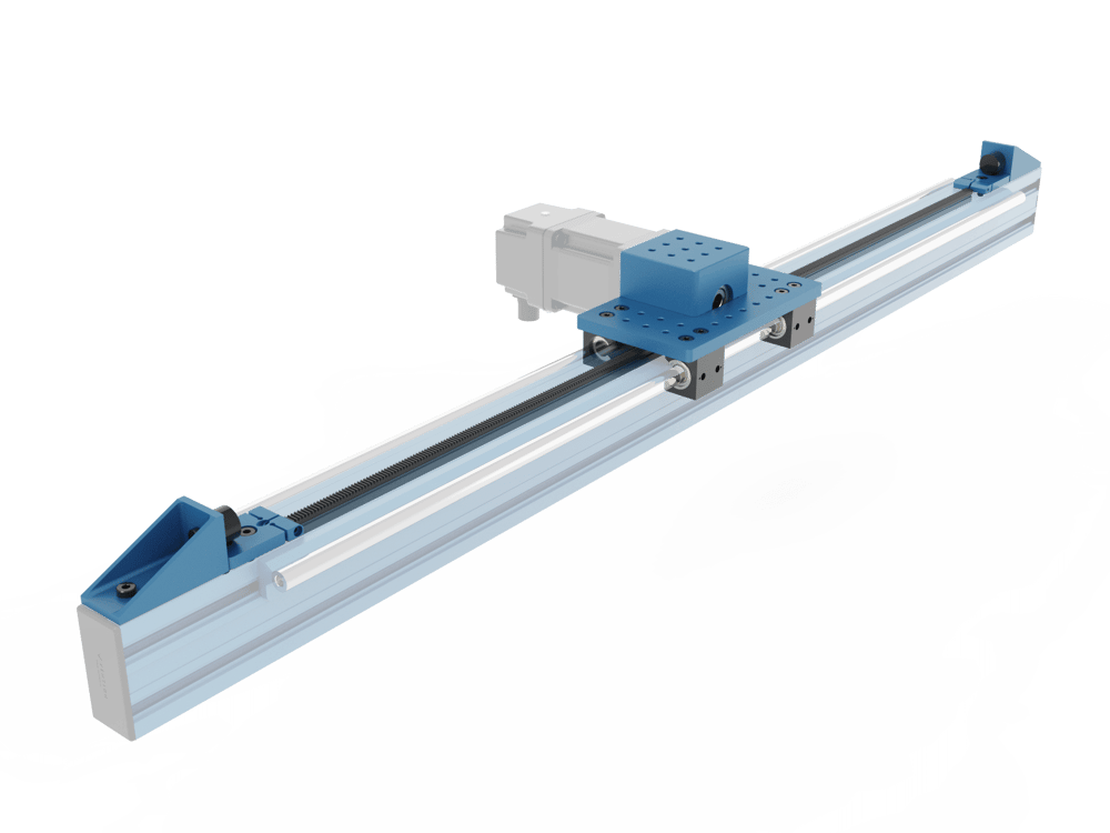
The rack and pinion actuator consists of rack segments installed into the extrusion frame and the pinion housing assembly mounted onto the frame through a set of linear guide bearings. The pinion housing assembly (MO-LM-019-0000) allows for any combination of Vention’s NEMA 34 stepper motors and/or Vention’s power transmission components to drive the actuator. With choices in motor type as well as the use of a gearbox, multiple levels of force can be achieved. The housing also features mounting holes that interface perfectly with Vention’s frame connectors and assembly plates. Two rack segment lengths (540mm and 810mm) are available and can be used in combination to create an actuator of any desired rack length.
This document covers requirements for current version of MachineMotion controller. For previous version, refer to link below:
Applications
There are several applications for rack and pinion systems. One ideal use is in high speed lifting operations, such as a Vention’s 3 or 4 axis palletizer z-axes. Another application where a rack and pinion system excels is in long range extenders or any application where actuation stroke of 3.3m or larger is needed.
Technical Specifications
Power Transmission Combinations
Motor Part Number | Max Force - Motor Only [N] | Max Force - Motor and Gearbox [N] |
MO-SM-030-0003 | 430 | 1000 (Limited by actuator wear rate) |
MO-SM-030-0002 | 250 | 1000 (Limited by actuator wear rate) |
MO-SM-030-0001 | 130 | 630 |
Specifications
Maximum Speed (mm/s) | 4000 (without gearbox) |
Axial Load Capacity (N) | 1000 |
Pinion Pitch Diameter (mm) | 45 |
Displacement Ratio (mm/turn) | 141.37 |
Repeatability including backlash (mm) | ±0.3 |
Total Backlash (mm) | 0.25 |
Motor Compatibility | All NEMA 34, 14mm shaft, 5mm key |
Force versus Speed
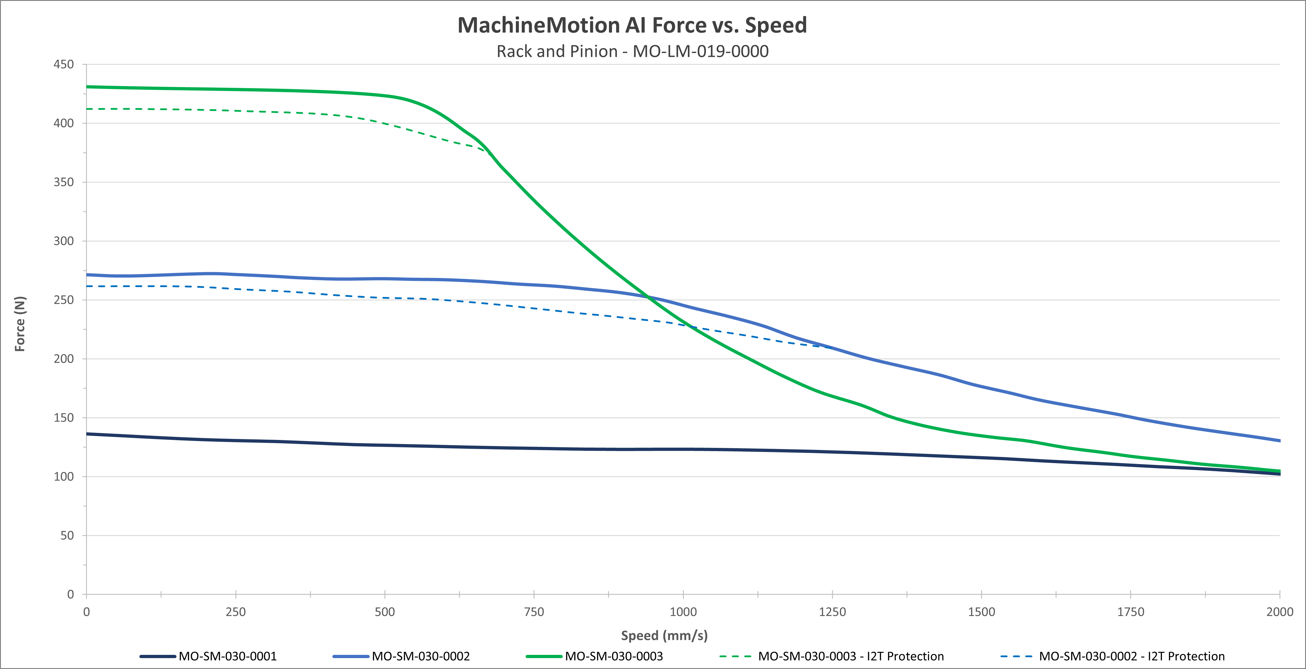 Exhibit 1. The above figure shows the expected performance with our three sizes of NEMA 34 motors: our 156mm motor (MO-SM-030-0003), our 100mm motor (MO-SM-030-0002), and our smallest 65mm motor (MO-SM-030-0001). |
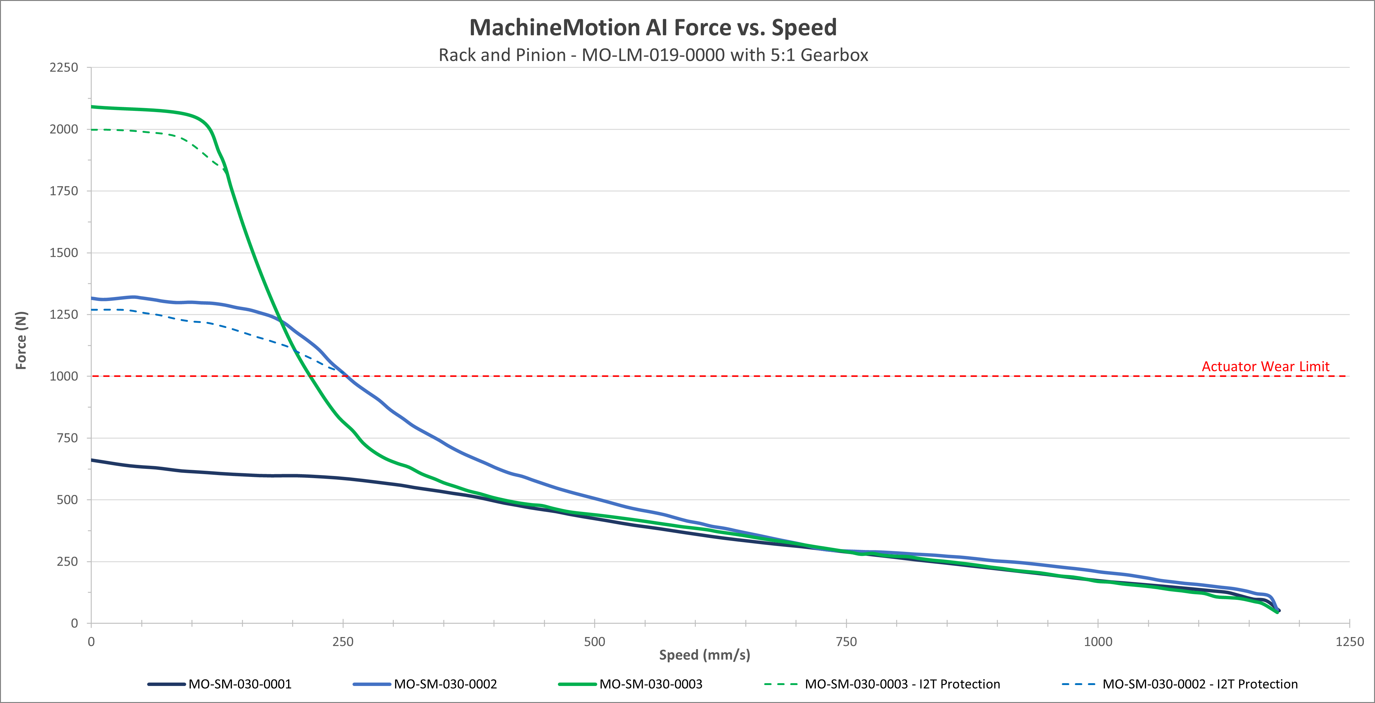 Exhibit 2. This figure shows the performance of the actuator with the same motors but a 5:1 planetary reduction gearbox (MO-PT-001-0001) is used to increase output force. |
Notes:
These performance curves are made with our motors and controller at steady state conditions. Using others motors or controllers will have different behavior therefore performance and reliability cannot be guaranteed.
Performance curves represent peak torque and speed values. Actual continuous performance may be lower due to I²t protection in the driver. For applications involving continuous, sustained torque output, contact Vention support for thermal derating guidelines or continuous-duty application advice.
Motors are equipped with an integrated safety mechanism known as I²T protection, which prevents overheating. This function continuously monitors the current drawn by the motor over time. If the motor operates at full load for an extended period (approximately 40–60 seconds), the I²T protection engages and limits the current, thereby reducing the available torque. The dashed lines in the graph illustrate the motor’s performance under these conditions. Once the motor has cooled sufficiently, it automatically returns to normal operating mode.
When two motors are mounted on the same actuator and operated in Cyclic Synchronous Torque (CST) mode, an increase in actuator output force of 1.8× can be expected. This performance gain is only applicable when both motors are synchronized in CST mode. Motors that are synchronized—but not operating in CST mode—do not yield this increase.
Selecting the right motion parameters
Determine motion requirements: Start by defining the load that needs to be moved and the required acceleration using basic kinematic equations.
Calculate required force: Apply Newton’s second law (F = m * a) to determine the resultant force the actuator must provide.
Reference performance curves: On the Force vs Speed graphs, locate the maximum achievable speed corresponding to the required force.
If operation is near the limits of the performance curve and you observe non-smooth motion or excessive following error (discrepancy between requested position and actual position), reduce the requested speed and/or acceleration. Lowering these values decreases system demand, which improves control stability and motion quality. Reducing the inertia ratio may also help the system response (see below).
Inertia Ratio
Calculating Inertia Ratio
Vention servo motor inertia values:
MO-SM-030-0003: 3.74×10⁻⁴ kg*m²
MO-SM-030-0002: 1.48×10⁻⁴ kg*m²
MO-SM-030-0001: 0.915×10⁻⁴ kg*m²
Sample Calculation
Standard Rack & Pinion actuator, with a 5:1 gearbox, moving 40kg + 10kg of external hardware (this include the mass of the motor), driven by a large motor.
Note: For most applications, an inertia ratio of 100:1 or lower is recommended. Adding a gearbox can help reduce the ratio. Generally, lowering the inertia ratio of a system results in a better response/control. If your application exceeds the recommended 100:1 inertia ratio, we encourage you to contact our Application Engineering team for a technical assessment of its feasibility.
Assembly Instructions
Slide the rack segments into the aluminum extrusion T-slots as shown. This can be done by hand or by using the rack installation tool, HW-TL-004-0001, that comes with your order.
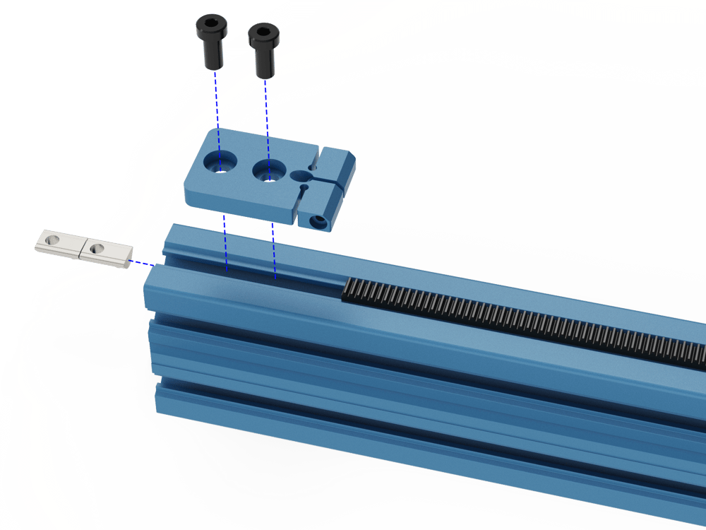
Install the Rack Compression Block at the end of the first segment using the included 16mm long M8 bolts (HW-FN-003-0016) ant T-Nuts (HW-FN-002-0001). For now, leave the M6 (HW-FN-013-0025) set screw and M4 clamping bolt (HW-FN-010-0030) loose or uninstalled; they will be covered in a future step.
Slide in the subsequent rack segments until all segments have been installed. This can be done by hand or by using the rack installation tool, HW-TL-004-0001, and a soft blow hammer if there is any resistance.
Once all segments have been installed, mount to second Rack Compression Block as shown, again using 16mm M8 bolts and T nuts.
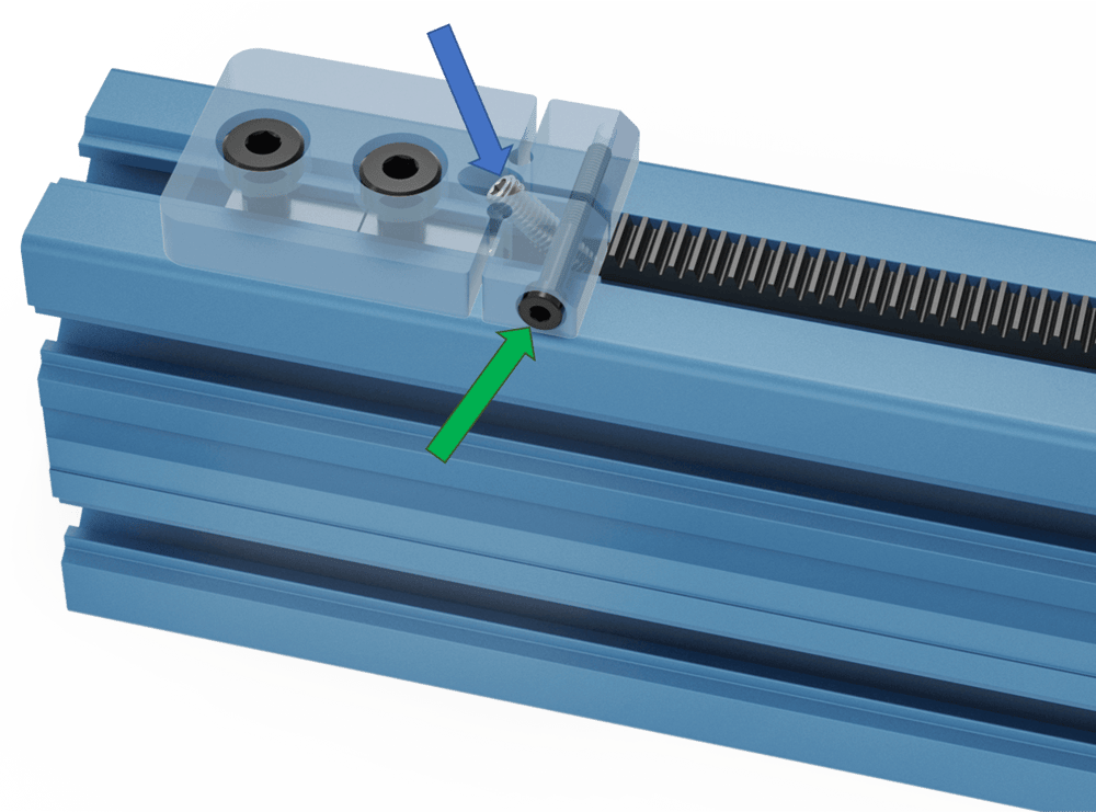
Once the compression block is fixed in place, install the M6 set screws, HW-FN-013-0025 (blue arrow) in each compression block. Additionally, install the M4 clamping bolt, HW-FN-010-0030 (green arrow) in the side of both compression blocks. The M4 should be snug but not tightened. Begin tightening both M6 set screws by even amounts on both compression blocks until all slack in the rack segments has been absorbed. Finally, tighten the M4 clamping bolts to prevent the M6 set screws from loosening.
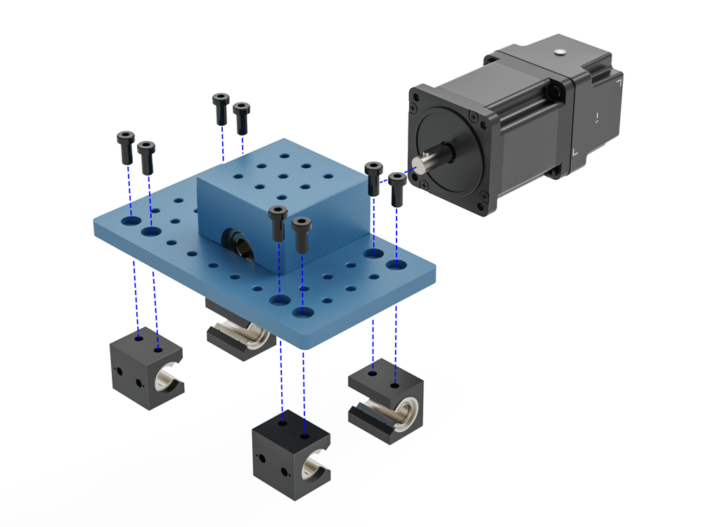
As received, the Housing and Pinion Assembly is already pre-assembled.
Mount the intended power transmission components such as the 5:1 gearbox and motor to the housing input shaft and attach the Rack and Pinion Housing to the extrusion via one of Vention’s linear guides such as the Vention 16mm linear guide rails (Assembly requires shaft MO-LM-014-XXXX and bearings MO-LM-010-0001) or the Vention roller wheels (assembly requires two eccentric wheels MO-LM-001-0027 and two concentric wheels MO-LM-001-0028). When installing the housing on linear bearings, ensure you use 12mm long M8 fasteners (HW-FN-003-0012).
Notes:
The bearings should be mounted on the rail before attaching the housing. The image below does not show the rails for visual clarity.
When installing motors, apply a small amount of grease to the motor shaft so that it is lightly coated. This will reduce the possibility of fretting corrosion occurring during operation, making future removal easier.
Moreover, do not use excessive force (hammering, prying or using screws to “push” the motor) to install the motor.
Once the housing is mounted, run the housing along the axis by hand ensuring that it is smooth and the pinion does not jam at any joint.
Mount external home and end position sensors as well as bump stop HW-BP-001-0004.
Be sure to apply grease to the racks and cycle the actuator back and forth by hand, ensuring the grease is distributed and coating the rack teeth. For more instructions on how to lubricate the actuator see the maintenance instructions here.
Assembly is complete.
Additional Assembly Tips
For custom length rack and pinions, the rack segments can be cut with a hack saw or grinder. If this is done, place the rough cut end at the very end of the actuator contacting the compression block so that the rough cut does not affect the meshing of the gear racks and pinion.