|
Overview
The Mode Switching Safety Module AI (CE-SA-018-0001__2) is ideal for applications where partial body entry into a machine is necessary without triggering an emergency stop (e-stop). A typical example is an operator replacing a part during machine tending. At each cycle, the machine’s automation program pauses for the time required by the operator to replace the part. A safe sensor (device A) detects the end of a cycle and mutes a light curtain (device B) for a few seconds until the operator completes the replacement. The program then resumes and the next cycle proceeds without an e-stop. If the operator’s hand enters the machine and crosses the light curtain at any other time during the cycle, it will immediately trigger an e-stop. This module can cover up to 2 zones with their own independent mode switching logic. Each zone requires 2 safety devices. Every safety equipment deployment should be paired with a safety assessment to ensure risk reduction.
This document covers requirements for latest version of Vention’s Mode Switching Safety Module. For previous version, refer to link below:
Features
Compatible with every model of MachineMotion AI
Configuration-free, plug-and-play
Daisy-chainable
For mode switching applications without full body entry
Latches faults from Device inputs to MachineMotion AI when mode switching logic is violated
2 independent mode switching zones
Compatible with Datalogic SG4 & Keyence GL-R light curtains
Compatible with Datalogic & Keyence laser scanners
Compatible with fail-safe inductive sensors
RGB LED indicator for safety status (emergency stop, faults)
Single-color LED indicators for power and communication status
Publishes safety state to the MachineMotion AI controller
Included cables
1x Safety Extension cable (5m) - CE-CA-102-5000__3
2x Safety Device Jumper - CE-SA-125-0001
1x Safety Jumper - CE-SA-102-0001
Safety

Vention’s safety modules perform safety functions as a part of a whole installation or machine. A complete safety system normally includes sensors or input units, logic units and contactors or output units. The manufacturer of the installation or machine is responsible for ensuring proper functioning of the whole system. The total concept of the control system into which the safety module is integrated must be validated by the user. Vention cannot guarantee all specifications of an installation or a machine without being responsible for the risk assessment and the design of the safety system. Vention takes over no liability for recommendations which are given or implied in the following description.
The following items must be taken into consideration during the design, risk assessment & installation of the safety system :
The Safety Modules shall be put into operation only after the safety functions have been tested during the commissioning.
According to EN IEC 60204-1:2018 and EN ISO 10218-1:2011 it is not allowed to restart automatically after emergency stop. Therefore the control systems of the connected devices have to disable the automatic start after emergency stop.
Opening the Safety Module or implementing unauthorized changes voids any warranty.

Functional error! Danger to life, risk of serious injuries or property damage
The Mode Switching Safety Module AI may only be used in VENTION safety ecosystem;
The Mode Switching Safety Module AI does not monitor the input redundant signals at the Device ports. If the connected devices do not have monitoring of its output signals, the performance level of the safety function can be reduced;
No emergency stop button shall be connected to the Safety IN port;
Mode switching is not designed for full body entry. As there is no latch on the monitoring of the safety device ports 1A and 2A, it is not acceptable to allow full body entry;
When using the mode switching function, it shall be ensured that the safety device ports 1B and 2B represent the safe state of the application. As there is no latch on the monitoring of the safety device ports 1B and 2B, these safety inputs shall always be low if the machinery is in an unsafe state or location;
The risk assessment shall demonstrate that when triggering the safety devices connected to the Device ports, the state of the machine and the safety distance are acceptable. Refer to ISO 13855 and ISO 13857 for additional considerations on safety distances;
The Mode Switching Safety Module AI is designed to operate in indoor environments without dust or high humidity. Dust and dampness may lead to malfunction. Do not install or operate the Safety Module outdoors;
The machine shall be designed in such a way that it is not possible to press the reset button from inside a safeguarded area without triggering one of the devices connected to the Device ports.
Technical specs
General Specifications
Item | Specification |
|---|---|
Part Number | |
Weight | 0.8kg |
Dimensions | 19.0 x 15.0 x 9.0mm |
Material |
|
Operating Temp | 0 to 40°C |
IP rating (IEC 60529) | IP54 |
Electrical Specifications
Item | Specification |
|---|---|
Nominal input voltage | 24 VDC (Class 2 or SELV power supply)** |
Input voltage range | 19.2 ~ 26.4 VDC |
Operating power consumption | 5 W without safety devices |
Short circuit protection | Internal electronic fuse, max 2.5A |
** Note: In North America, the Safety Module shall be supplied by a certified class 2 power supply. In Europe, the Safety Module must be supplied by an SELV circuit. When powered by the MachineMotion AI those requirements are met.
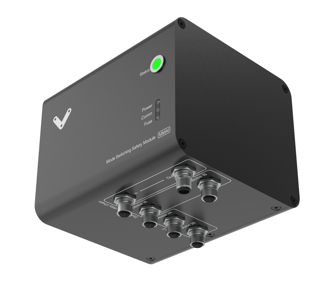
Physical Interface
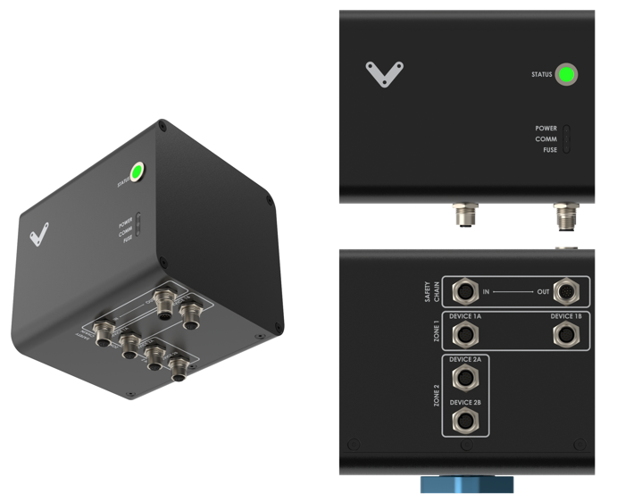 Figure 1: Physical Interface |
LED Indicators
Name | LED Color | Indicates (when ON) |
|---|---|---|
POWER | White | Power supplied to the module |
COMM | White | Ethernet communication functional |
FUSE | Red | Module internal fuse tripped |
STATUS | Off | Module disconnected |
STATUS | Green | System operational |
STATUS | Orange | Error |
STATUS | Red | Emergency stop due to upstream module |
STATUS | Blinking Red | Emergency stop due to mode switching violation |
STATUS | Blinking Blue | Mode switching active |
Functionality
In a given zone (Zone 1 or Zone 2), if Device A and Device B are triggered at the same time, the module will trigger and latch a fault on the Safety Out towards the MachineMotion AI controller. The fault is latched until a reset signal is received. The 2 zones’ logic operate independently.
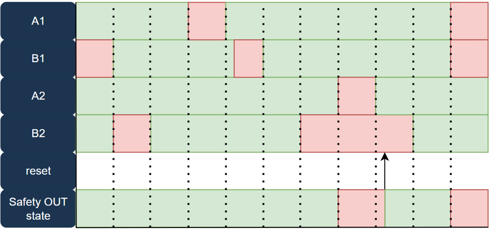 Figure 2: Mode switching logic |
Port Definitions
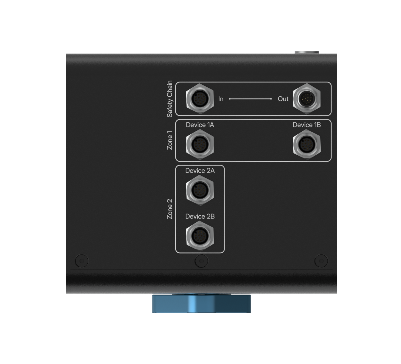 Figure 3: Mode Switching Safety Module AI ports |
Safety Out - M12, male, 12-pin, A-Keyed
The Safety Out port connects to the Safety In port of the MachineMotion AI, or to another Safety Module when daisychaining.
Pin | Function |
|---|---|
Pin 1 | 24 VDC input |
Pin 2 | 0V input |
Pin 3 | OSSD output A |
Pin 4 | 24 VDC input |
Pin 5 | OSSD output B |
Pin 6 | 24 VDC input |
Pin 7 | Reset input |
Pin 8 | 0V |
Pin 9 | Ethernet RX+ |
Pin 10 | Ethernet RX- |
Pin 11 | Ethernet TX+ |
Pin 12 | Ethernet TX- |
Safety In - M12, female, 12-pin, A-Keyed
The Safety In port connects to the Safety Out port of another Safety Module when daisychaining. If the port is unused, plug the included yellow jumper (CE-SA-102-0001).
Pin | Function |
|---|---|
Pin 1 | 24 VDC output |
Pin 2 | 0V output |
Pin 3 | OSSD input A |
Pin 4 | 24 VDC output |
Pin 5 | OSSD input B |
Pin 6 | 24 VDC output |
Pin 7 | Reset output |
Pin 8 | 0V output |
Pin 9 | Ethernet RX+ |
Pin 10 | Ethernet RX- |
Pin 11 | Ethernet TX+ |
Pin 12 | Ethernet TX- |
Device 1A/1B & Device 2A/2B - M12, female, 12-pin, A-Keyed
The Device 1A/1B and Device 2A/2B ports connect to safety devices. If any of these ports is unused, plug the included black jumper (CE-SA-125-0001).
Pin | Function |
|---|---|
Pin 1 | 24V (fused) |
Pin 2 | 0V |
Pin 3 | NC |
Pin 4 | NC |
Pin 5 | OSSD input A |
Pin 6 | NC |
Pin 7 | NC |
Pin 8 | OSSD input B |
Pin 9 | NC |
Pin 10 | NC |
Pin 11 | NC |
Pin 12 | 0V |
Mounting
Install the module mounting bracket (CE-HW-005-1002) to the extrusion with the screws provided (HW-FN-003-0018). Install the module onto the mounting bracket as illustrated below.
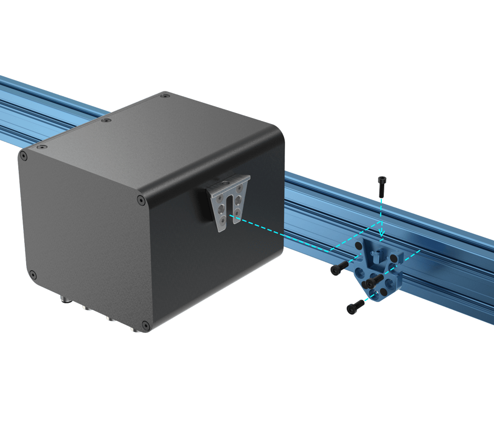 Figure 4: Module Mounting | 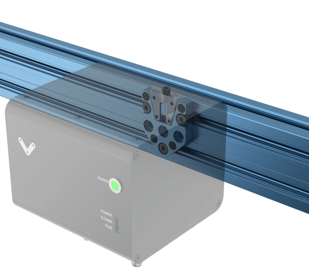 Figure 5: Module Mounting |
Wiring Diagram
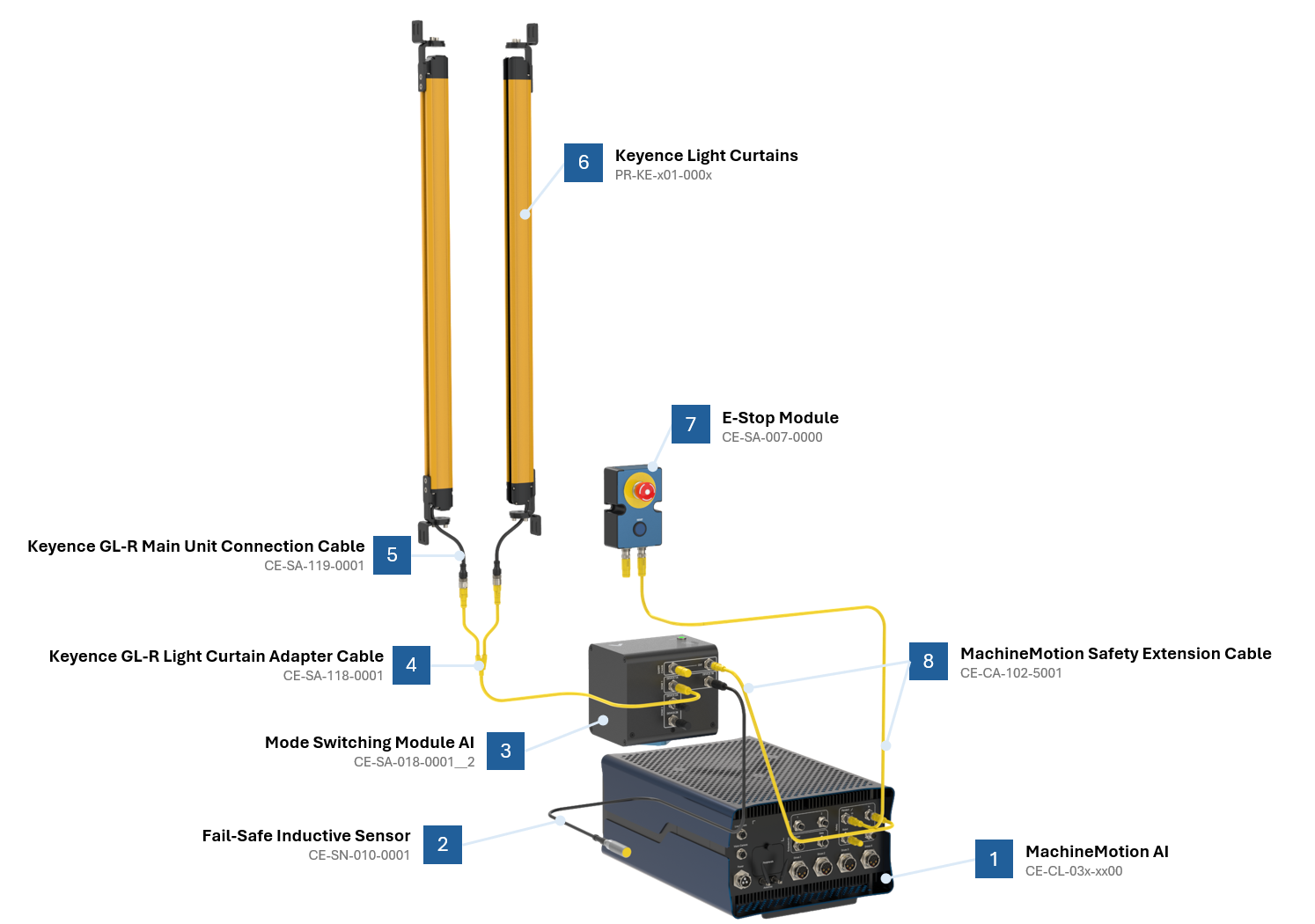 Figure 6: Mode Switching Safety Module AI wiring diagram |
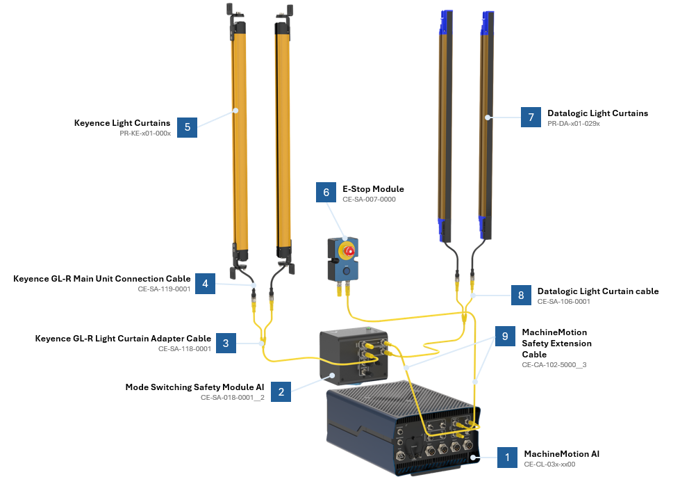 Figure 7: Mode Switching Safety Module AI wiring diagram with 2x Light Curtains |
*Note: Insert a jumper on any unused safety input for proper functionality. See table below to identify the appropriate jumper part number (included with the module).
Jumper Part Number | Description | Target module | Port restrictions |
|---|---|---|---|
CE-SA-125-0001 | M12, male, 12 pins, black jumper | Muting Safety Module AI (CE-SA-015-0001__2) | Strictly reserved for Device ports |
CE-JP-000-0002 | M12, male, 4 pins, yellow jumper | Access Request Module AI (CE-SA-017-0001__2) | Strictly reserved for End Effector port |
CE-SA-102-0001 | M12, male, 12 pins, yellow jumper | All modules | Other unused safety input ports |
Important information
The electronic fuse contained in the Mode Switching Safety Module AI protects from internal faults and external faults, but only on the Device ports. The 24V power output on the Safety In port is not protected by the electronic fuse. The electronic fuse has an auto-retry mechanism (it does not latch faults and does not require a power cycle to reset).
Safety Data
The Vention’s Safety Modules realize the following safety functions :
System emergency stop output at the Safety OUT connector from the Safety IN port (E-stop_SafetyIN-to-SafetyOUT);
The Device port (light-curtain or area scanner) to the Safety OUT portSystem emergency stop output at the Safety OUT connector from a Safety Device port (E-stop_Device-to-SafetyOUT); and
System reset propagation from the Safety IN port to the Safety OUT port (Reset_SafetyOUT).
For each of these functions, safety data can be found in the following table.
For each of these functions performed by the Robot Safety Module, safety data can be found in the following table:
Safety Function | PL | Cat. | MTTFd | DCavg | PFHd | Response time |
|---|---|---|---|---|---|---|
E-stop_SafetyIN-to-SafetyOUT | e | 3 | 224 | 99% | 4.29E-08 | 20 ms |
E-stop_Device-to-SafetyOUT | e | 3 | 224 | 99% | 4.29E-08 | 20 ms |
Reset_SafetyOUT | c | 1 | >100 | N/A | 1.14E-06 | Not Applicable |
The above information have been calculated based on the following operation conditions:
Data | Value | Unit |
|---|---|---|
dop | 365 | days/years |
hop | 24 | hours/days |
tcycle | 8640 | s/cycle |