Overview
The Momentary Pushbutton Module, CE-MD-014-0001, extends MachineMotion functionality with two momentary pushbuttons. This plug-and-play module only requires a single connection to the MachineMotion controller. Compatible modules, such as the Power Switch (CE-MD-005-0000) & additional pushbutton modules can also be daisy chained to each other, making it possible to connect up to sixteen modules per MachineMotion controller.
This document covers requirements for current version of MachineMotion controller. For previous version, refer to link below:
Features
Includes two momentary pushbuttons
Connects (daisy chain) with compatible modules
Configurable address
Technical Specifications
General Specifications
Part Number | CE-MD-014-0001 |
Certifications |
|
Weight | 0.45 kg |
Dimensions | 46 x 88 x 133.0 mm |
Material |
|
Operating Temperature | 0 to 40°C |
IP rating (IEC 60529) | IP54 |
Included in the Box |
|
Momentary Pushbutton Module Physical Interface
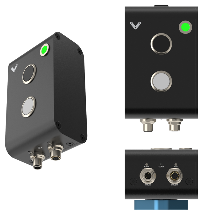 Figure 1: Physical interface |
Status LED Indicators
Name | LED Color | Indicated (when ON) |
|---|---|---|
POWER | White | 24 VDC supplied to module |
COMM | Yellow and Blue | RS-485 communication functional |
FUSE | Red | Module internal fuse tripped |
Pushbuttons (black/white)
Pushbutton type | Momentary |
Mechanical life (minimum) | 250,000 operations |
Connecting to a MachineMotion Controller
.png) Figure 2: Momentary Pushbutton module with MachineMotion AI |
CTRL IN Male M12 connector pinout
Pin | Description |
|---|---|
Pin 1 | 24V (input) |
Pin 2 | 0V (input) |
Pin 3 | RS-485 A (input) |
Pin 4 | RS-485 B (input) |
Pin 5 | Reserved |
Pin 6 | Reserved |
Pin 7 | Reserved |
Pin 8 | Reserved |
CTRL OUT Female M12 connector pinout
Pin | Description |
|---|---|
Pin 1 | 24V (output) |
Pin 2 | 0V (output) |
Pin 3 | RS-485 A (output) |
Pin 4 | RS-485 B (output) |
Pin 5 | Reserved |
Pin 6 | Reserved |
Pin 7 | Reserved |
Pin 8 | Reserved |
LED color
If you are using the Momentary Pushbutton in conjunction with an Access Request Module (CE-SA-017-0001), you may be interested in replicating the LED color of the Access Request Module on the Momentary Pushbutton, to ensure that the LEDs have the same behavior.
The Momentary Pushbutton exposes a REST interface to set the color of its LED.
firmware/control-port/<port>/set-led
Description
Set LED color on connected Pushbutton modules.
Format
URL:
POST <machineMotionIp>/firmware/control-port/<port>/set-led
Where:
<machineMotionIp>is the IP address of the MachineMotion<port>is the port number the module is connected to. It can be1or2.
Payload:
[
  {
    "id": integer,
    "red": 0 or 1,
    "green": 0 or 1,
    "blue": 0 or 1,
    "blink": 0 or 1
  }
]
Where:
<id>is the Pushbutton module’s address<red>is the red color of the RGB LED. 0 means OFF, 1 means ON.<green>is the green color of the RGB LED. 0 means OFF, 1 means ON.<blue>is the blue color of the RGB LED. 0 means OFF, 1 means ON.<blink>sets the behaviour of the RGB LED. 0 means the LED will be continuously ON, 1 means it will blink every 1.5 sec.
Usage example
curl -X 'POST' \
  'https://machinemotion.local/firmware/control-port/1/set-led' \
  -H 'accept: application/json' \
  -H 'Content-Type: application/json' \
  -d '[
  {
    "id": 2,
    "red": 1,
    "green": 0,
    "blue": 1,
    "blink": 1
  }
]'
Will set the LED of the Pushbutton module having the address 2 and connected to the Control port 1 of the MachineMotion, to blink with the color purple.
Momentary Pushbutton module address configurations
Below are the valid address configurations that can be used for the Pushbutton module:
Switches | Switches | |||||||
Device ID | Device Type | |||||||
1 | 2 | 3 | 4 | 5 | 6 | 7 | 8 | |
OFF | OFF | OFF | OFF | ON | ON | OFF | OFF | Momentary Pushbutton Module 1 |
ON | OFF | OFF | OFF | ON | ON | OFF | OFF | Momentary Pushbutton Module 2 |
OFF | ON | OFF | OFF | ON | ON | OFF | OFF | Momentary Pushbutton Module 3 |
ON | ON | OFF | OFF | ON | ON | OFF | OFF | Momentary Pushbutton Module 4 |
OFF | OFF | ON | OFF | ON | ON | OFF | OFF | Momentary Pushbutton Module 5 |
ON | OFF | ON | OFF | ON | ON | OFF | OFF | Momentary Pushbutton Module 6 |
OFF | ON | ON | OFF | ON | ON | OFF | OFF | Momentary Pushbutton Module 7 |
ON | ON | ON | OFF | ON | ON | OFF | OFF | Momentary Pushbutton Module 8 |
OFF | OFF | OFF | ON | ON | ON | OFF | OFF | Momentary Pushbutton Module 9 |
ON | OFF | OFF | ON | ON | ON | OFF | OFF | Momentary Pushbutton Module 10 |
OFF | ON | OFF | ON | ON | ON | OFF | OFF | Momentary Pushbutton Module 11 |
ON | ON | OFF | ON | ON | ON | OFF | OFF | Momentary Pushbutton Module 12 |
OFF | OFF | ON | ON | ON | ON | OFF | OFF | Momentary Pushbutton Module 13 |
ON | OFF | ON | ON | ON | ON | OFF | OFF | Momentary Pushbutton Module 14 |
OFF | ON | ON | ON | ON | ON | OFF | OFF | Momentary Pushbutton Module 15 |
ON | ON | ON | ON | ON | ON | OFF | OFF | Momentary Pushbutton Module 16 |