Overview
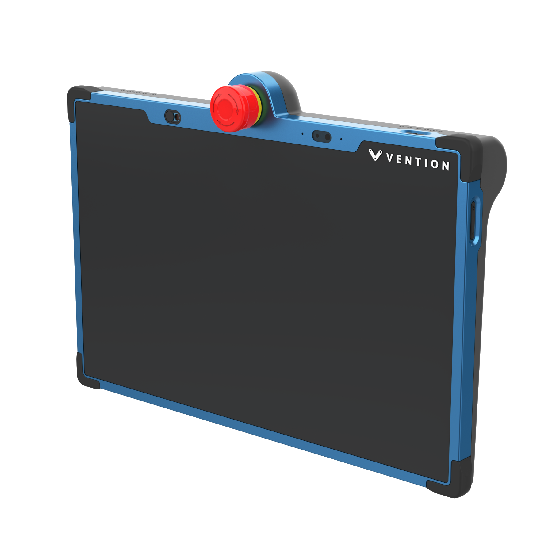
MachineMotion Pendant V4 provides a plug and play touch screen interface for automated equipment powered by Vention’s MachineMotion controller. At 13 inches with two cameras, this Pendant generation is designed to be ergonomically friendly allowing easy operation through a responsive advanced display. When connected to the MachineMotion controller, the Pendant enables machine operators and administrators to run and modify their program in a code-free environment. This product comes with pre-loaded control and machine operations software. Compatible with MachineMotion (CE-CL-030-0000, CE-CL-031-0000, CE-CL-030-1500, CE-CL-031-3000, CE-CL-010-0001 & CE-CL-010-0004). This new version of Pendant includes front and rear cameras for the Remote Support feature. It also includes Safety IN & Safety OUT connectors to be daisy-chained with safety modules and devices on the safety loop.
This document covers requirements for current version of MachineMotion Pendant V4. For previous version, refer to link below:
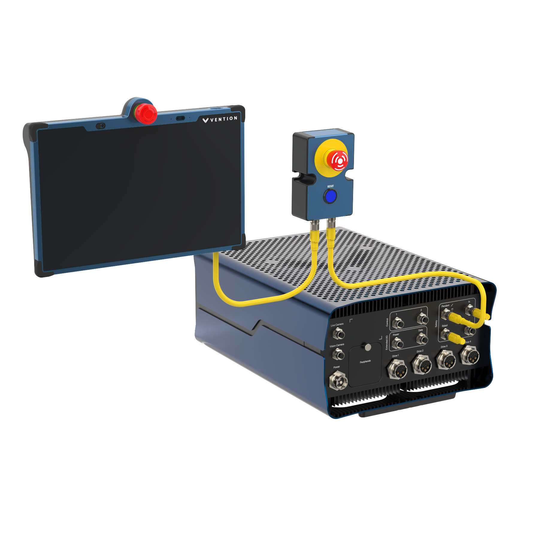 Figure 1: MachineMotion with Pendant V4 |
Features
Plug and Play compatibility with MachineMotion controller
Pre-loaded MachineLogic, for code-free automation sequence editing
Application launcher for machine operators
Manual machine operation mode
Detect and connect to a desired Wi-Fi network
Front and rear facing cameras for Remote Support function (to be purchased separately)
Safety IN & Safety OUT connectors for daisy-chaining on Vention safety loop
IP54 industrial enclosure
Volume & Power buttons
Camera privacy covers
Multiple mounting options: Horizontal, Vertical, VESA
Important Notes
Safety
.png) The Pendant V4 displays an emergency stop button and can act as an input unit of safety functions.
The Pendant V4 displays an emergency stop button and can act as an input unit of safety functions.
A complete safety system normally includes sensors or input units, logic units and contactors or output units. The manufacturer of the installation or machine is responsible for ensuring proper functioning of the whole system and validating the control system into which the Pendant V4 is integrated. Vention cannot guarantee all specifications of an installation or a machine without being responsible for the risk assessment and the design of the safety system. Vention takes over no liability for recommendations which are given or implied in the following description.
The following items must be taken into consideration during the design, risk assessment & installation of the safety system :
The emergency stop button of the Pendant V4 shall not be put into operation only after the safety functions have been tested during the commissioning.
Fault masking shall be considered.
The use of the Pendant V4 does not prevent the automatic start of the devices connected to the Safety OUT ports. According to EN IEC 60204-1:2018 and EN ISO 10218-1:2011 it is not allowed to restart automatically after emergency stop. Therefore the control systems of the connected devices have to disable the automatic start after emergency stop.
The Pendant V4 must connected to the MachineMotion’s Pendant / E-stop port. If not an Estop-reset-module (CE-SA-007-0001) must be connected to the Safety IN port
If the Pendant V4 is the last device on the MachineMotion’s Pendant / E-stop port, a Safety Jumper (CE-SA-102-0001) must be installed on the Pendant V4 Safety In port.
Opening the Pendant V4 or implementing unauthorized changes voids any warranty.
![]() WARNING
WARNING
Functional error! Danger to life, risk of serious injuries or property damage
The Pendant V4 can only be connected to Vention safety devices on the MachineMotion’s Pendant / E-stop port.
The Pendant V4 is designed to operate in indoor environments without dust or high humidity. Dust and dampness may lead to malfunction. Do not install or operate the Safety Module outdoors.
![]() NOTE
NOTE
Avoid touching the screen during startup, as this may interfere with the screen calibration process.
Control Center Software Included
MachineMotion comes with pre-loaded operations software called Control Center. Control Center is accessible through the MachineMotion Pendant or via a laptop with an Ethernet connection.
For more information about the Control Center software, please see the MachineMotion User Manual.
Technical Specifications
Mechanical Specifications
Item | Specification |
|---|---|
Vibration resistance | Enclosure validated as per IEC-60068-2-6 :
|
Shock resistance | Enclosure validated as per IEC-60068-2-27 :
|
Ingress protection | IP54 (category 2 for dust) |
Mounting |
|
Electrical Specifications
Item | Specification |
|---|---|
Processor | Intel® Pentium® Processor N6415, 4 cores and up to 3.00 GHz |
Graphics Display | 1920x1080 LCD screen with Anti-Glare & Anti-Fingerprint coating |
Memory | 8GB LPDDR4 on board |
Storage | 256G UFS 2.1 |
Front and rear facing cameras |
|
Audio |
|
Network and Communication | Wi-Fi 5 (IEEE Std. 802.11 a/b/g/n/ac) (Dual band) 2*2 |
Ethernet Switch | 5 ports 10/100MB |
Nominal Power Consumption | 12W |
Maximum Power Consumption | 20W |
Nominal Input Voltage | 24V |
Safety Cable length connected to Safety OUT | Up to 50m |
Emergency Stop Button | 3x NC Dry contact channels |
Connectors |
|
Hardware Compatibility |
|
Pin Out
Safety IN – M12A-12 pins Female
Pin | Description |
|---|---|
1 | 24V |
2 | 0V |
3 | MachineMotion Safety Channel 1 Contact 1 |
4 | MachineMotion Safety Channel 1 Contact 2 |
5 | MachineMotion Safety Channel 2 Contact 1 |
6 | MachineMotion Safety Channel 2 Contact 2 |
7 | Reset Contact 1 |
8 | Reset Contact 2 |
9 | Safety IN Ethernet TX+ |
10 | Safety IN Ethernet TX- |
11 | Safety IN Ethernet RX+ |
12 | Safety IN Ethernet RX- |
Safety OUT – M12A-12 pins Male
Pin | Description |
|---|---|
1 | 24V |
2 | 0V |
3 | MachineMotion Safety Channel 1 Contact 1 |
4 | MachineMotion Safety Channel 1 Contact 2 |
5 | MachineMotion Safety Channel 2 Contact 1 |
6 | MachineMotion Safety Channel 2 Contact 2 |
7 | Reset Contact 1 |
8 | Reset Contact 2 |
9 | Safety OUT Ethernet TX+ |
10 | Safety OUT Ethernet TX- |
11 | Safety OUT Ethernet RX+ |
12 | Safety OUT Ethernet RX- |
Physical Interface
Power Button Functionality
Pressing once on the power button while the Pendant V4 is OFF will power it ON.
Pressing more than 10 seconds on the power button while the Pendant is ON will power it OFF.
The Pendant goes into low brightness mode after 30 minutes of no interaction. Pressing once on the power button while the Pendant is ON and in low brightness mode will change the display to full brightness.
If the Pendant is not connected to a MachineMotion controller, it will power OFF after 10 minutes.
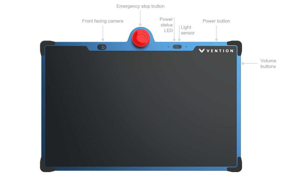
Figure 2: Pendant V4 Front
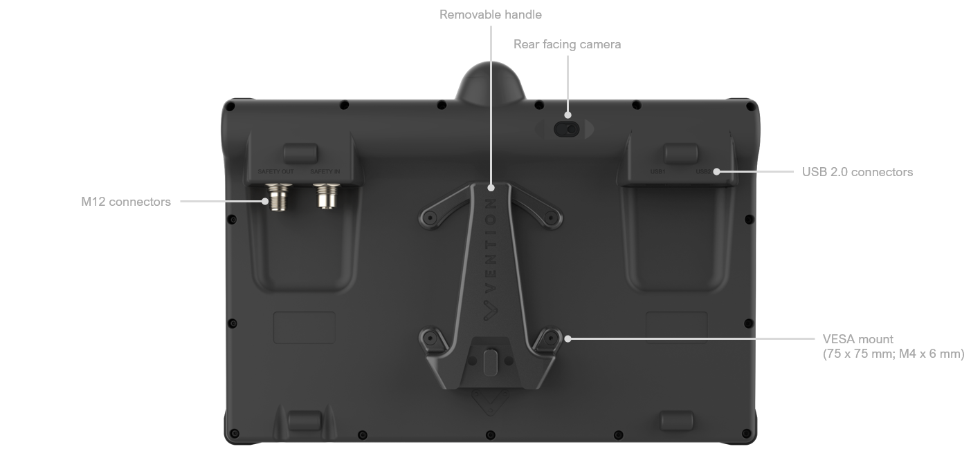
Figure 3: Pendant V4 Back
Mounting Options
The Pendant V4 can be mounting to a machine using one of the mounting options below:
Vertical static mounting bracket (CE-TP-024-0014)
Horizontal static mounting bracket (CE-TP-024-0014)
VESA mount adapter with quick disconnect feature (CE-TP-024-0015)
Safety Data
The Pendant V4 displays an emergency stop button which is connected to the safety loop of a MachineMotion.
When evaluating the performance of a safety function utilizing the Pendant V4 attention shall be made in regards to the number of daisy chained emergency stop buttons and interlock devices. Fault masking reduces the performance level of the safety function. Guidance on fault masking can be found in ISO/TR 24119.
Safety data can be found in the following table depending on if the Pendant V4 is daisy chained or not.
Function | PL | Cat. | MTTFd | DCavg |
|---|---|---|---|---|
Pendant V4 - Daisy Chained | d | 3 | 697 | 60.01% |
Pendant V4 Single unit | e | 3 | 698 | 97.72% |
The above information have been calculated based on the following operation conditions :
Data | Value | Unit |
|---|---|---|
dop | 365 | days/years |
hop | 24 | hours/days |
tcycle | 8640 | s/cycle |
EU Declaration of Conformity
The Pendant V4 is in compliance with the Machinery directive, the RoHS directive and the RED. The EU declaration of conformity is available in the documentation section of the product details page of the Pendant V4.
Electromagnetic Emission and Radio Frequency compliance statements
The MachineMotion Pendant v4 is a mobile device that comply with global RF exposure requirements. Specific Absorption Rate (SAR) refers to the rate at which the body absorbs RF energy. The SAR limit is 1.6 watts per kilogram in countries that set the limit averaged over 1 gram of tissue and 2.0 watts per kilogram in countries that set the limit averaged over 10 grams of tissue.
During testing, the MachineMotion Pendant v4 radios are set to their highest transmission levels and SAR is evaluated in real-time, over time intervals as specified by applicable regulations. When the device is evauated in positions that simulate use against the body (separation distance of 5 mm), the SAR testing results are below the limits :
Max 0.644 W/kg over 1 g (SAR1g limit : 1.6 W/kg)
Max 0.620 W/kg over 10 g (SAR10g limit : 2 W/kg)
FCC statement
The MachineMotion Pendant v4 has been tested and found to comply with the limits for a Class A device as per Part 15 of the FCC Rules. These limits are designed to provide reasonable protection against harmful interference in an industrial environment. This equipment generates, uses, and can radiate radio frequency energy and, if not installed and used in accordance with the instructions, may cause harmful interference to radio communications.
This device complies with Part 15 of the FCC Rules. Operation is subject to the following two conditions:
(1) this device may not cause harmful interference, and
(2) this device must accept any interference received, including interference that may cause undesired operation.
ISED statement
The MachineMotion Pendant v4 complies with CAN ICES-003(A)/NMB-003(A).
This device contains licence-exempt transmitter(s)/receiver(s) that comply with Innovation, Science and Economic Development Canada's licence-exempt RSS standard(s). Operation is subject to the following two conditions:
(1) This device may not cause interference, and
(2) This device must accept any interference, including interference that may cause undesired operation of the device.