|
Overview
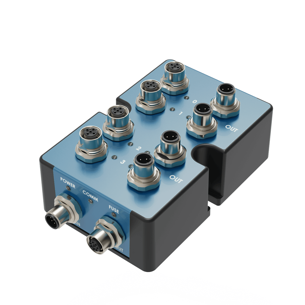
The Digital I/O Module v2, CE-MD-001-0000__2, extends MachineMotion’s functionality with 4 (NPN or PNP) inputs and 4 PNP outputs. This plug-and-play module only requires a single connection to the MachineMotion controller. Compatible modules, such as the Power Switch (CE-MD-005-0000) & additional Digital I/O Module v2 modules can also be daisy chained to each other, making it possible to connect up to sixteen modules per MachineMotion controller.
For details on Vention’s Digital IO Module V1, refer to the ‘Documentation for Previous Product Versions’ section at the bottom of this page.
Features
4 Inputs compatible with NPN and PNP sensors
4 PNP Outputs
Connects (daisy chain) with compatible modules
Configurable address
Plug-and-play access from the Control Center, MachineLogic, and Python API
Programming Options
Program the Digital I/O Module v2 using [MachineLogic] or the [Python API]. It can also be accessed from the Control Center.
Technical Specifications
General Specifications
Part Number | CE-MD-001-0000__2 |
|---|---|
Certifications |
|
Weight | 1.5 kg |
Dimensions | 60 x 88 x 150 mm |
Material |
|
Operating Temperature | 0 to 40°C |
Included in the Box |
|
Performance and Other Specifications
Specification | Value |
|---|---|
Input supply voltage | 24VDC nominal |
Digital input impedance | 10kΩ pull-up to 24V and 10kΩ pull-down to 0V |
Digital input active NPN voltage range (logical ‘1’) | Below 6V |
Digital input active PNP voltage range (logicial ‘1’) | Above 18V |
Digital input inactive voltage range (logical ‘0’) | Between 6V and 18V |
Digital input - minimum recommended sensor output impedance | NPN: 10kΩ to 24V |
Digital output maximum current | 70mA each |
Maximum current for IN/OUT ports 24VDC pins | 2A shared |
Latency (with 2 modules connected to the MachineMotion controller) | 125ms max. |
Latency has been obtained by connecting a digital output port to a digital input port, and by measuring the delay between requesting the change of output state and reading the change of input state.
Physical Interface
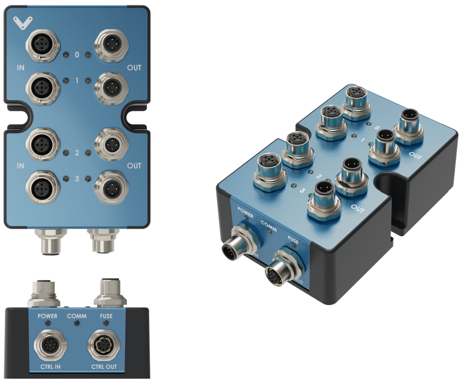 Digital I/O Module v2 Physical Interface |
CTRL IN Male M12 connector pinout
Pin | Description |
|---|---|
Pin 1 | 24V (input) |
Pin 2 | 0V (input) |
Pin 3 | RS-485 A (input) |
Pin 4 | RS-485 B (input) |
Pin 5 | Reserved |
Pin 6 | Reserved |
Pin 7 | Reserved |
Pin 8 | Reserved |
CTRL OUT Female M12 connector pinout
Pin | Description |
|---|---|
Pin 1 | 24V (output) |
Pin 2 | 0V (output) |
Pin 3 | RS-485 A (output) |
Pin 4 | RS-485 B (output) |
Pin 5 | Reserved |
Pin 6 | Reserved |
Pin 7 | Reserved |
Pin 8 | Reserved |
IN Female M12 connector pinout
Pin | Description |
|---|---|
Pin 1 | 24V (2A max. shared with other pins) |
Pin 2 | Input |
Pin 3 | 0V |
Pin 4 | NC |
OUT Male M12 connector pinout
Pin | Description |
|---|---|
Pin 1 | 24V (2A max. shared with other pins) |
Pin 2 | Output (70mA max. per output) |
Pin 3 | 0V |
Pin 4 | NC |
Digital I/O module v2 address configurations
Below are the valid address configurations that can be used for the Digital I/O module v2
Valid address configurations
Switches | Switches | |||||||
Device ID | Device Type | |||||||
1 | 2 | 3 | 4 | 5 | 6 | 7 | 8 | |
OFF | OFF | OFF | OFF | OFF | OFF | OFF | OFF | Digital I/O Module 1 |
ON | OFF | OFF | OFF | OFF | OFF | OFF | OFF | Digital I/O Module 2 |
OFF | ON | OFF | OFF | OFF | OFF | OFF | OFF | Digital I/O Module 3 |
ON | ON | OFF | OFF | OFF | OFF | OFF | OFF | Digital I/O Module 4 |
OFF | OFF | ON | OFF | OFF | OFF | OFF | OFF | Digital I/O Module 5 |
ON | OFF | ON | OFF | OFF | OFF | OFF | OFF | Digital I/O Module 6 |
OFF | ON | ON | OFF | OFF | OFF | OFF | OFF | Digital I/O Module 7 |
ON | ON | ON | OFF | OFF | OFF | OFF | OFF | Digital I/O Module 8 |
OFF | OFF | OFF | ON | OFF | OFF | OFF | OFF | Digital I/O Module 9 |
ON | OFF | OFF | ON | OFF | OFF | OFF | OFF | Digital I/O Module 10 |
OFF | ON | OFF | ON | OFF | OFF | OFF | OFF | Digital I/O Module 11 |
ON | ON | OFF | ON | OFF | OFF | OFF | OFF | Digital I/O Module 12 |
OFF | OFF | ON | ON | OFF | OFF | OFF | OFF | Digital I/O Module 13 |
ON | OFF | ON | ON | OFF | OFF | OFF | OFF | Digital I/O Module 14 |
OFF | ON | ON | ON | OFF | OFF | OFF | OFF | Digital I/O Module 15 |
ON | ON | ON | ON | OFF | OFF | OFF | OFF | Digital I/O Module 16 |