This document covers requirements for current version of MachineMotion controller. For previous version, refer to link below:
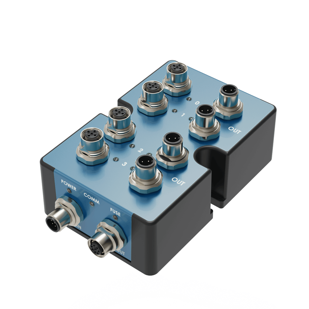
Status LED Indicators
Name | LED Color | Indicated (when ON) |
|---|---|---|
POWER | White | 24 VDC supplied to module |
COMM | Yellow and Blue | RS-485 communication functional |
FUSE | Red | Module internal fuse tripped |
STATUS LED - OUT | White | Active (24V) |
STATUS LED - IN | White | Active (24V or 0V) |
Resetting the electronic fuse
The Digital I/O Module v2 has an internal resettable electronic fuse that will trip in case of a short-circuit between the power pins (24V and 0V). This may occur when connecting a faulty or miswired device to the module, or even by touching pin #1 and pin #3 of any digital input/output port with a metallic object. If the fuse trips on a given module, the FUSE status LED will turn on red, but modules connected on the same daisychain will not be affected since each of them has its own fuse. To reset the fuse, simply disconnect and reconnect the cable on the CTRL IN port.
Applications
Connecting to MachineMotion (directly)
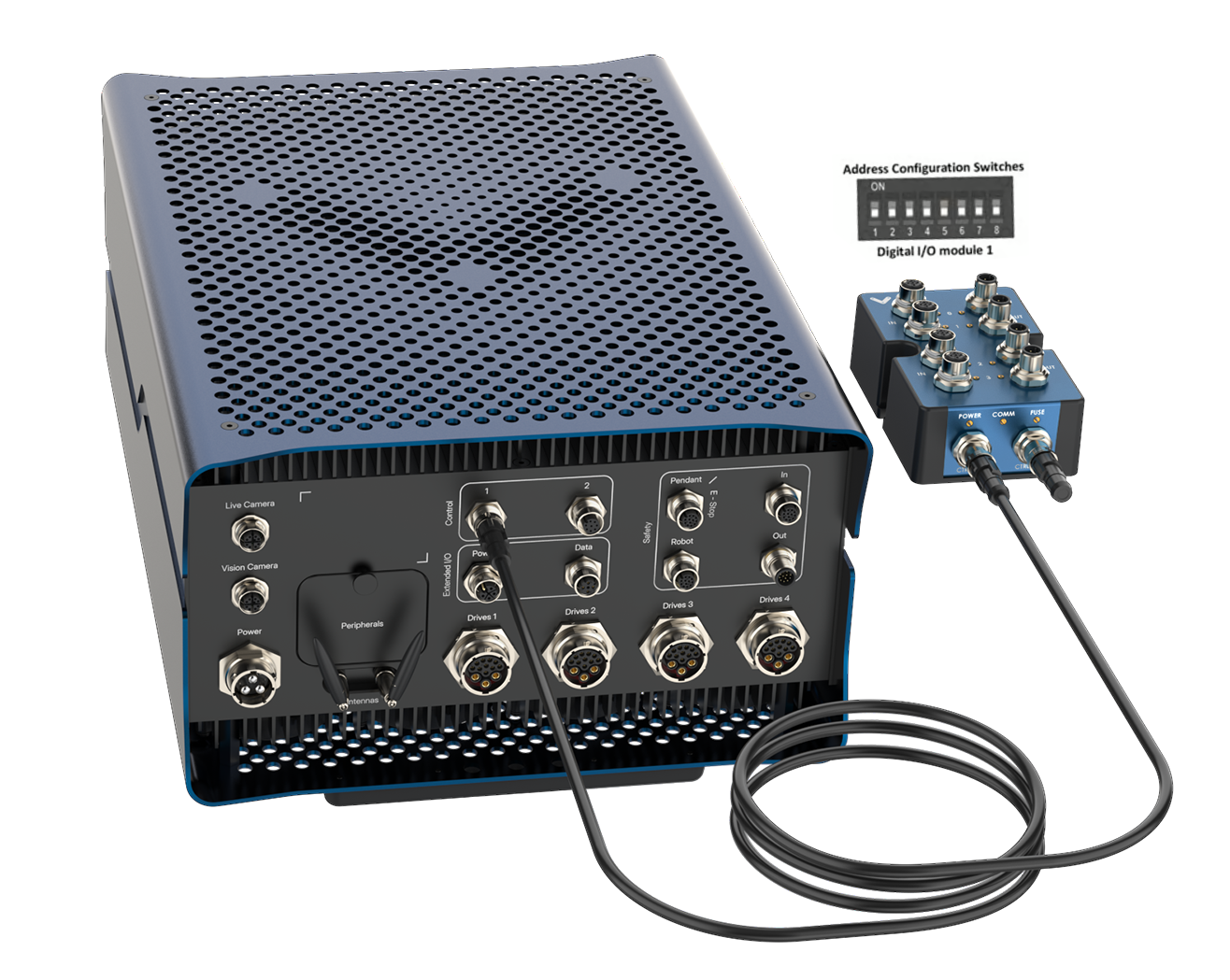 Figure 1 - Connecting Digital I/O v2 directly to MachineMotion AI |
To connect a Digital I/O Module v2 directly to MachineMotion AI (see Figure 1):
Set the address of the Digital I/O Module v2, as explained in the Setting the address configuration switches section below.
Using the Control Device Extension Cable (CE-CA-022-5000):
Connect the male end to any CONTROL port on MachineMotion.
Connect the female end to the CTRL IN port on the Digital I/O Module v2.
Connect the Module Termination Jumper (CE-JP-001-0001), to the CTRL OUT port on the Digital I/O Module v2.
Connecting to MachineMotion (daisy chain)
.png) Figure 2 - Daisy chaining Digital IOs MachineMotion AI |
Compatible modules, including the Digital I/O Module v2 can also be connected via daisy chain to a single CONTROL port on the MachineMotion AI controller (see Figure 2). Across all two CONTROL ports, the controller supports up to sixteen modules at the same time, provided they all have distinct addresses (see Address configuration switches).
To connect several modules in a daisy chain:
Set a distinct address for every module of the daisy chain, as explained in the section Setting the address configuration switches.
Using a Control Device Extension Cable (CE-CA-022-5000):
Connect the male end to any CONTROL port on MachineMotion.
Connect the female end to the CTRL IN port on the first module of the daisy chain.
For every additional module to be connected in the daisy chain, repeat this step using an additional Control Device Extension Cable (CE-CA-022-5000):
Connect the male end to the CTRL OUT port on the previous module in the daisy chain.
Connect the female end to the CTRL IN port on the current module in the daisy chain.
Connect the Module Termination Jumper (CE-JP-001-0001), to the CTRL OUT port on the last module in the daisy chain.
Connecting non-Vention components as digital inputs/outputs
While every Vention component (sensors, pneumatic manifolds, etc.) is compatible with the Digital I/O Module v2 out-of-the-box, other external devices can also be easily connected to the module.
Important note: to mitigate ESD (electrostatic discharge) damage, it is highly recommended to use shielded cables (such as CE-CA-018-5000) between input/output devices and the Digital I/O Module v2, especially when doing field-wiring. If the end device does not have a shield or a metallic enclosure, extend the cable shield as close as possible to the device. Every M12 connector port on the module is bonded to Earth ground. This is especially relevant with dress kits running along robotic arms and pneumatic tubing, since they are prone to ESD.
To connect a non-Vention device as a digital input (e.g. sensors, switches, etc.):
The signal can be either NPN (sinking, active 0V) or PNP (sourcing, active 24V).
If the device uses a M12, 4-pin, A-keyed, male interface with the signal on pin #2, you can connect it directly to any module input.
If the device does not use such interface or if the signal is on a different pin, use field-wireable male connector adapter CE-CN-030-0001 with the pinout shown below.
Digital Input Pin | Description |
|---|---|
Pin 1 | 24V |
Pin 2 | Input (Hybrid NPN/PNP) |
Pin 3 | 0V |
Pin 4 | Not Connected |
To connect a non-Vention device as a digital output (e.g. valve, relay, LED, etc.):
The activating signal has to be PNP, operate at 24V and consume no more than 100mA.
If the device uses a M12, 4-pin, A-keyed, female interface with the signal on pin #2, you can connect it directly to any module output.
If the device does not use such interface or if the signal is on a different pin, use field-wireable female connector adapter CE-CN-048-0002 with the pinout shown below.
Digital Output Pin | Description |
|---|---|
Pin 1 | 24V |
Pin 2 | Output (PNP) |
Pin 3 | 0V |
Pin 4 | Not Connected |
Setting the address configuration switches
Each module has an address with two components: device ID and device type. Both device ID and device type are set by changing the state of the address configuration switches, which are located at the back of the Digital I/O Module v2 under a removable rubber cap.
Switches 1 to 4 define the module device ID and allow the MachineMotion AI controller to know which module it is communicating with. Every module connected to the same controller should have a distinct device ID, regardless of its device type.
Switches 5 to 8 define the module device type and their positions should remain identical for all modules of the same type.
The table below lists every valid address for the Digital I/O Module v2. An individual switch is considered ON when the selector is slid up and OFF when the selector is slid down.
Switches | Switches | |||||||
Device ID | Device Type | |||||||
1 | 2 | 3 | 4 | 5 | 6 | 7 | 8 | |
OFF | OFF | OFF | OFF | OFF | OFF | OFF | OFF | Digital I/O Module 1 |
ON | OFF | OFF | OFF | OFF | OFF | OFF | OFF | Digital I/O Module 2 |
OFF | ON | OFF | OFF | OFF | OFF | OFF | OFF | Digital I/O Module 3 |
ON | ON | OFF | OFF | OFF | OFF | OFF | OFF | Digital I/O Module 4 |
OFF | OFF | ON | OFF | OFF | OFF | OFF | OFF | Digital I/O Module 5 |
ON | OFF | ON | OFF | OFF | OFF | OFF | OFF | Digital I/O Module 6 |
OFF | ON | ON | OFF | OFF | OFF | OFF | OFF | Digital I/O Module 7 |
ON | ON | ON | OFF | OFF | OFF | OFF | OFF | Digital I/O Module 8 |
OFF | OFF | OFF | ON | OFF | OFF | OFF | OFF | Digital I/O Module 9 |
ON | OFF | OFF | ON | OFF | OFF | OFF | OFF | Digital I/O Module 10 |
OFF | ON | OFF | ON | OFF | OFF | OFF | OFF | Digital I/O Module 11 |
ON | ON | OFF | ON | OFF | OFF | OFF | OFF | Digital I/O Module 12 |
OFF | OFF | ON | ON | OFF | OFF | OFF | OFF | Digital I/O Module 13 |
ON | OFF | ON | ON | OFF | OFF | OFF | OFF | Digital I/O Module 14 |
OFF | ON | ON | ON | OFF | OFF | OFF | OFF | Digital I/O Module 15 |
ON | ON | ON | ON | OFF | OFF | OFF | OFF | Digital I/O Module 16 |
Configuring the Digital I/O Module v2
Configure your Digital I/O module v2 in order to utilize it with MachineLogic, following the steps below:
Open your MachineBuilder design.
Open the Configuration section in the right pane.
Select the Digital I/O Module v2 you would like to configure.
Fill out the following fields:
MachineMotion Port: Represents the port number of the MachineMotion the Digital I/O module v2 is plugged into.
Device ID: Represents the device ID of your module. The device ID is configured on the physical module using address configuration switches, therefore, ensure the device ID configured in this dropdown matches the address configuration switches on the physical module.
Input Name / Output Name: Give each of your Digital I/O module v2 pins a friendly name, which will be used to program them in MachineLogic.
Deploy the Configuration to your MachineMotion following the steps provided in this document.
Figure 3: Digital I/O module v2 configuration in MachineBuilder |
.png)
Testing the Digital I/O Module v2 in Control Center
To test the configured Digital I/O Module v2, open the MachineMotion’s Control Center (via the Teach Pendant, or by connecting your laptop to the “To PC” Ethernet port, and navigating to the URL “machinemotion.local” in the Chrome browser).
Via the top navigation bar, select the Manual Control page.
In the left pane, select the Digital Inputs/Outputs section.
You should see your Digital I/O Module v2, as long it has been properly connected to the MachineMotion.
You can test the Digital I/O Module v2 inputs by monitoring their state change between 0 and 1. You can test the Digital I/O Module v2 outputs by clicking the toggle 0/1 to check if the device connected to the Digital I/O Module v2 toggles on and off.
Note: If you connect a new Digital I/O Module v2 to the MachineMotion, you might need to refresh the Control Center view in order to see it appear in the Manual Control page. Select another section, and click again on the Digital Inputs/Outputs section.
|
.png)
Programming the Digital I/O Module v2 with MachineLogic
To program your Digital I/O module v2 in MachineLogic, ensure you have completed the steps in Configuring the Digital I/O Module v2.
Go to the MachineLogic tab.
Click Add command > Add Output:
Under Output, selecting Digital Output
Under Output Name select your device
Under Value, select the state that you would like your device to be in
Click Add command > Add Wait:
Under Wait For, selecting Digital Input Transition would allow your program to wait for a Digital input rising edge or falling edge before playing the next command.
Click Add command > Add Wait:
Under Wait For, selecting Digital Input would allow your program to wait for a Digital input to be 0 or 1 before playing the next command.
It is also possible to get the state of the Digital Input into a Variable.
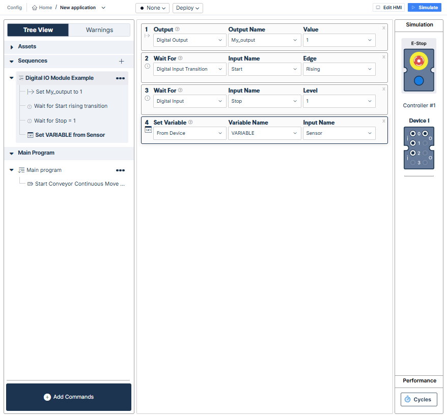
Figure 5: Wait for digital input transition
Using the Digital I/O Module v2 with the Python API
The Digital IO module can also programmed using the Vention Python API. The full API documentation can be accessed here