|
|---|
Overview
Vention offers a range of motors that are compatible with the MachineMotion AI controller. Depending on your application and technical requirements, compare the specifications of each motor below.
This document covers requirements for current version of MachineMotion controller. For previous version, refer to link below:
MachineMotion AI Motors
|
|
|
| |
Name | ||||
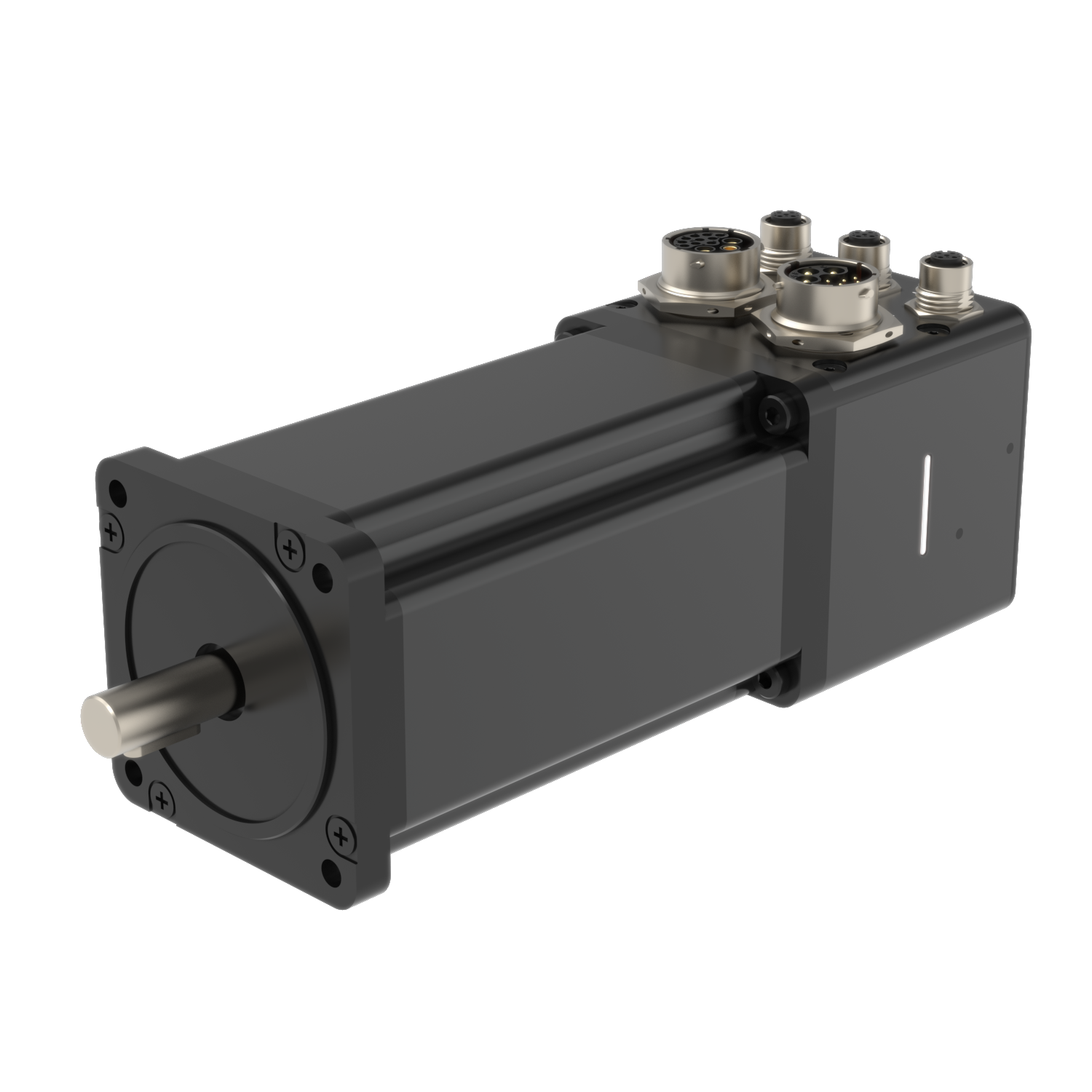
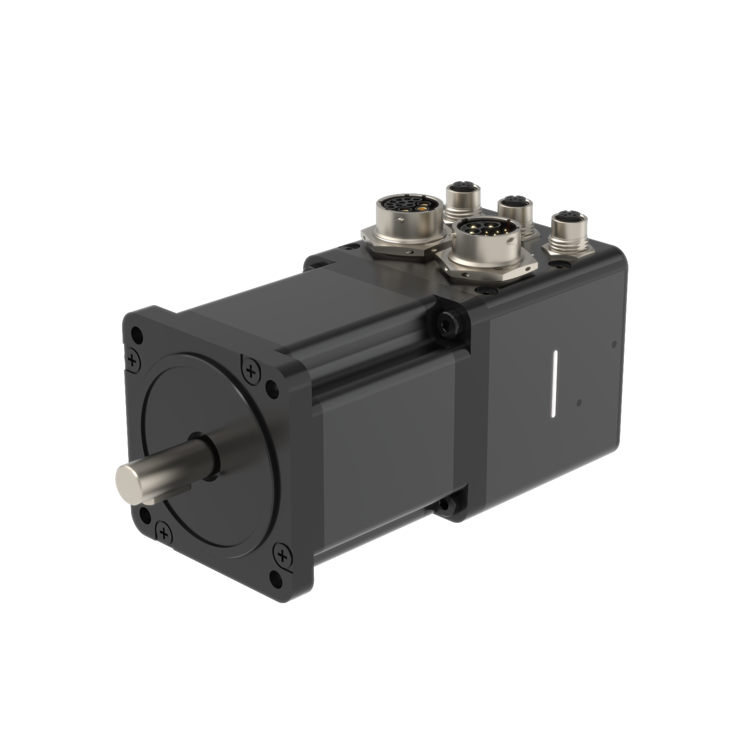
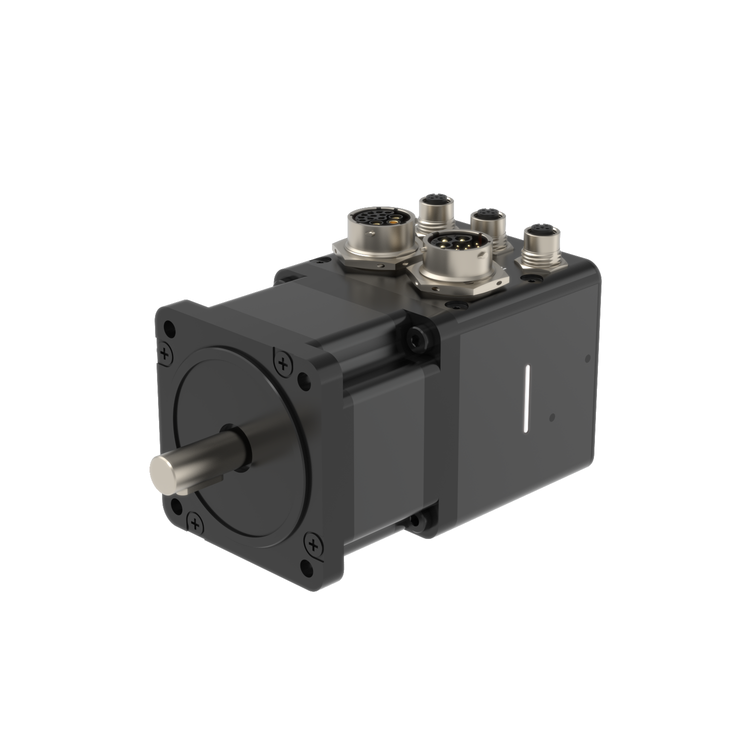
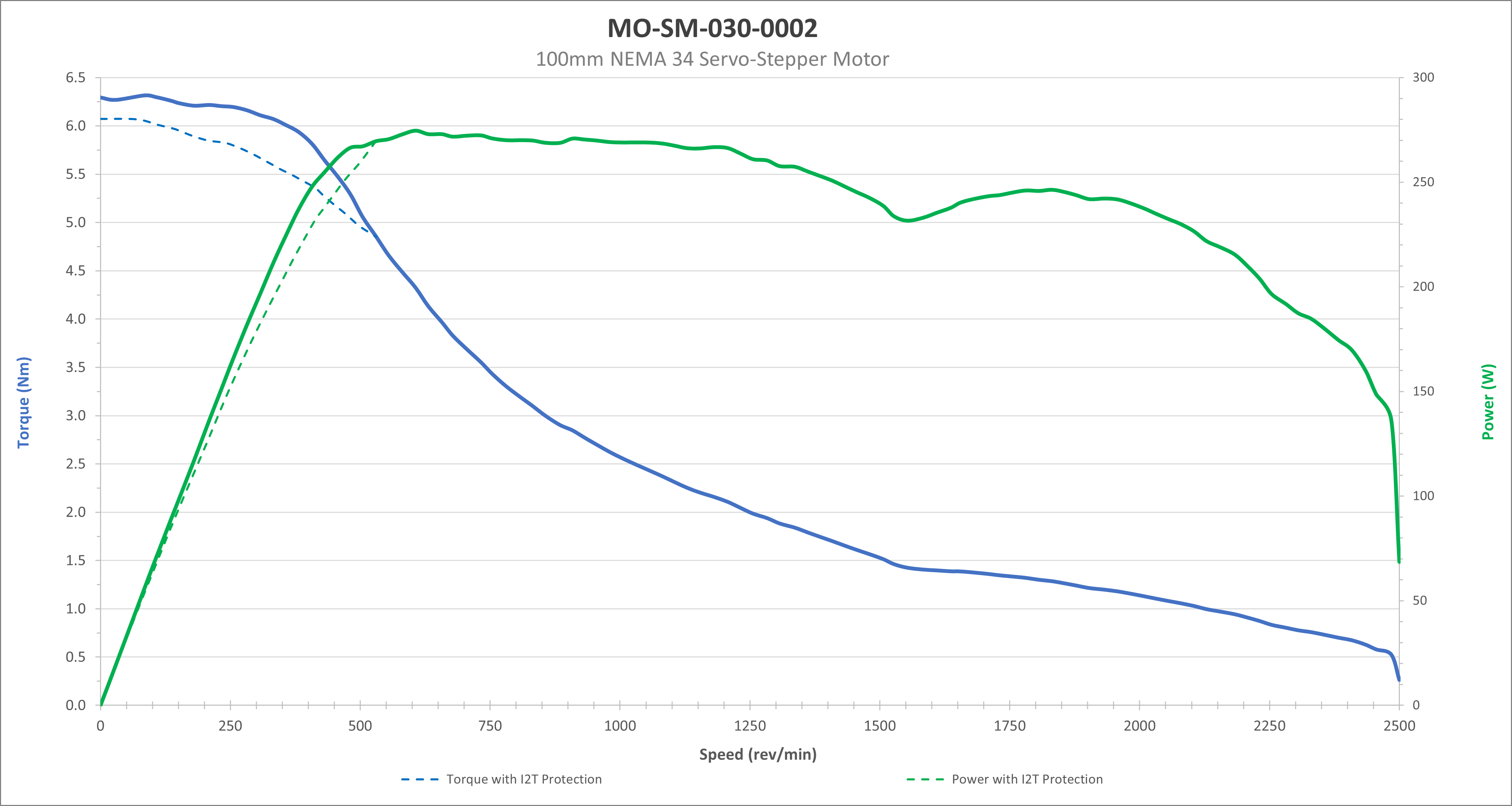
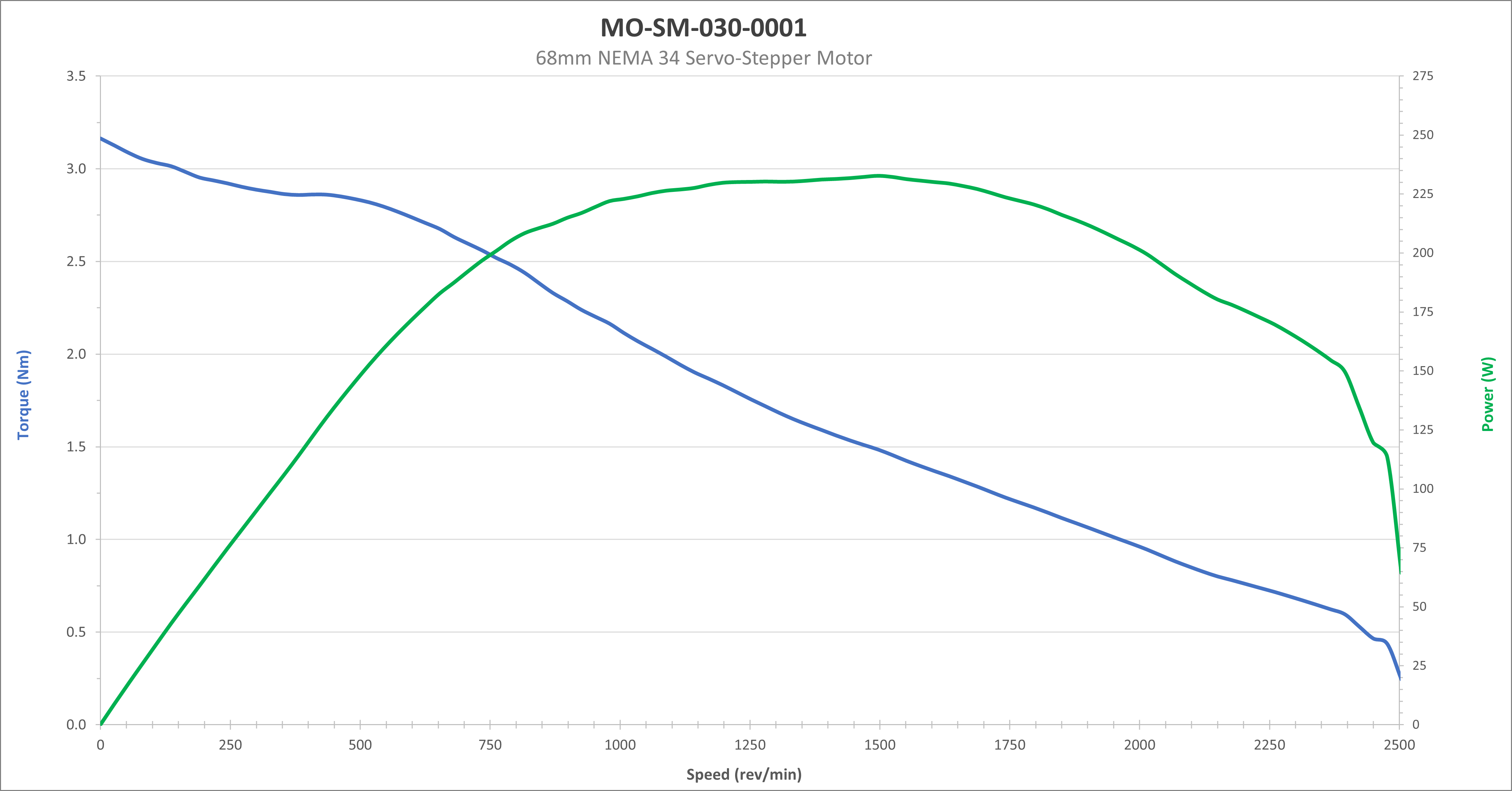
Part Number | MO-SM-030-0004 | MO-SM-030-0003 | MO-SM-030-0002 | MO-SM-030-0001 |
Included cable | 2-meter signal-power hybrid cable | 5-meter signal-power hybrid cable | 5-meter signal-power hybrid cable | 5-meter signal-power hybrid cable |
Motor Type | Servo | Hybrid Stepper Servo | Hybrid Stepper Servo | Hybrid Stepper Servo |
Motor Flange | NEMA 34 | NEMA 34 | NEMA 34 | NEMA 34 |
Motor Length | 157 mm | 157 mm | 96 mm | 66.5 mm |
Step Angle | 1.8° ± 5% | 1.8° ± 5% | 1.8° ± 5% | 1.8° ± 5% |
Holding Torque | 10 Nm | 10 Nm | 6.3 | 3.2 Nm |
Output shaft | 14 mm | 14 mm | 14 mm | 14 mm |
Input Voltage (Motion) | 60-80V, 72V nominal | 60-80V, 72V nominal | 60-80V, 72V nominal | 60-80V, 72V nominal |
Maximum Input Current (Motion) | 5A | 5A | 5A | 5A |
Maximum Motor Phase Current | 10A RMS | 10A RMS | 10A RMS | 10A RMS |
Maximum Mechanical Power (Torque x Speed) | 260W | 260W | 260W | 240W |
Input Voltage (Drive Logic) | 20-28V, 24V nominal | 20-28V, 24V nominal | 20-28V, 24V nominal | 20-28V, 24V nominal |
Maximum Input Current (Drive Logic) | 0.2A | 0.2A | 0.2A | 0.2A |
Communication Protocol | CANopen over EtherCAT (CoE) | CANopen over EtherCAT (CoE) | CANopen over EtherCAT (CoE) | CANopen over EtherCAT (CoE) |
Power-Signal ports (IN/OUT) | Amphenol Sine Systems ecomate® RM Hybrid connector (3 power pins, 10 signal pins) | Amphenol Sine Systems ecomate® RM Hybrid connector (3 power pins, 10 signal pins) | Amphenol Sine Systems ecomate® RM Hybrid connector (3 power pins, 10 signal pins) | Amphenol Sine Systems ecomate® RM Hybrid connector (3 power pins, 10 signal pins) |
Sensor ports (A/B) | M12 A-coded female *See Sensor Compatibility and Integration Specifications section below | M12 A-coded female | M12 A-coded female | M12 A-coded female |
Brake port | N/A | M12 D-coded female | M12 D-coded female | M12 D-coded female |
Operating Temperature | 0℃ to + 40℃ | 0℃ to + 40℃ | 0℃ to + 40℃ | 0℃ to + 40℃ |
Relative Humidity | 0% -85% RH, non-condensing, non-splash | 0% -85% RH, non-condensing, non-splash | 0% -85% RH, non-condensing, non-splash | 0% -85% RH, non-condensing, non-splash |
Vibration | IEC 60068-2-6
| IEC 60068-2-6
| IEC 60068-2-6
| IEC 60068-2-6
|
Shock | IEC 60068-2-27
| IEC 60068-2-27
| IEC 60068-2-27
| IEC 60068-2-27
|
Motor Insulation Class | B | B | B | B |
Motor Insulation Resistance | 100 Mohm | 100 Mohm | 100 Mohm | 100 Mohm |
Housing Material | Steel (motor) and aluminum (junction box) | Steel (motor) and aluminum (junction box) | Steel (motor) and aluminum (junction box) | Steel (motor) and aluminum (junction box) |
Overall Width | 86 mm | 86 mm | 86 mm | 86 mm |
Overall Length | 258 mm | 258 mm | 198 mm | 168 mm |
Overall Height | 103 mm | 103 mm | 103 mm | 103 mm |
Weight | 6.37 kg | 6.37 kg | 4.53 kg | 3.43 kg |
Daisy Chainable | Yes, refer to MachineMotion AI Controller User Manual | Yes, refer to MachineMotion AI Controller User Manual | Yes, refer to MachineMotion AI Controller User Manual | Yes, refer to MachineMotion AI Controller User Manual |
Certifications | cETL,
EU DoC,
FCC, ISED
| cETL,
EU DoC,
FCC, ISED
| cETL,
EU DoC,
FCC, ISED
| cETL,
EU DoC,
FCC, ISED
|
Safety data - EN ISO 13849-1 | PLe / Cat3 MTTFd : 337 years DCavg : Medium PFHd : 4.29E-08 | PLe / Cat3 MTTFd : 337 years DCavg : Medium PFHd : 4.29E-08 | PLe / Cat3 MTTFd : 337 years DCavg : Medium PFHd : 4.29E-08 | PLe / Cat3 MTTFd : 337 years DCavg : Medium] PFHd : 4.29E-08 |
Compatibility |

.png)
Sensor Compatibility and Integration Specifications for the Conveyor Motor (MO-SM-030-0004)
1. General Interface Requirements
The Conveyor motor sensor inputs are configured for NPN logic on Pin 2. Compatibility is determined by the output pin assignment of the sensor:
Pin 2 NPN Output: Compatible via direct connection using cable series CE-CA-018-xxxx (where xxxx denotes length in mm).
Pin 4 NPN Output: Requires the CE-CA-073-0001 adapter cable installed in series.
2. Keyence Sensor Compatibility Matrix
Vention Part Number | Compatibility Status | Requirement |
|---|---|---|
CE-SN-007-0007 | Native | Direct Connection |
CE-SN-007-0009 | Native | Direct Connection |
CE-SN-007-0011 | Native | Direct Connection |
CE-SN-007-0016 | Native | Direct Connection |
CE-SN-007-0021 | Configurable | Field Configuration Required |
CE-SN-007-0023 | Native | Direct Connection |
3. IFM Sensor Compatibility Matrix
Vention Part Number | Compatibility Status | Requirement |
|---|---|---|
CE-SN-004-0001 | Native | Direct Connection |
CE-SN-004-0003 | Native | Direct Connection |
CE-SN-006-0001__2 | Compatible | Adapter CE-CA-073-0001 |
CE-SN-006-0004__2 | Incompatible | PNP Output Only |
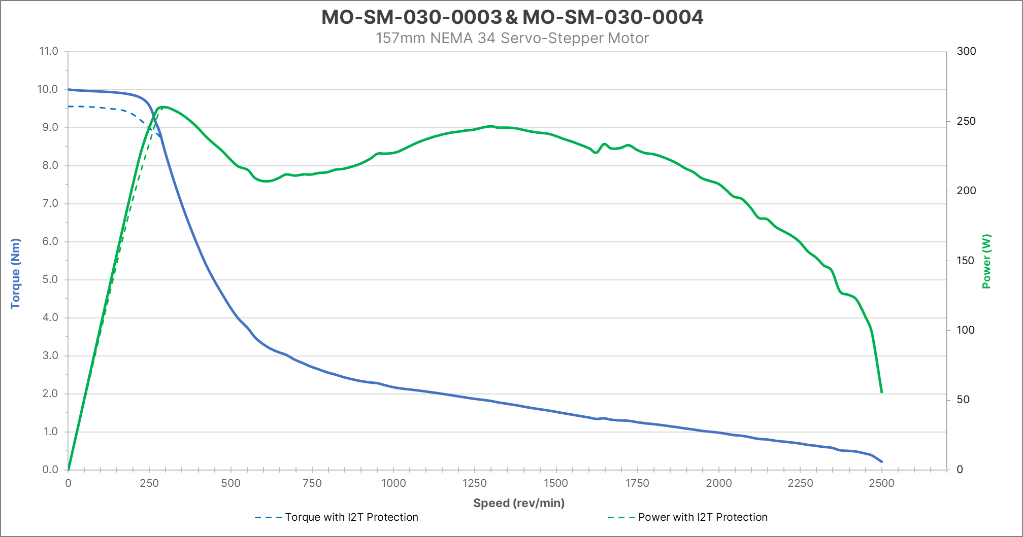
Motor torque-speed curves
|
|
|
Motor connector pinouts
Pin | IN | OUT |
|---|---|---|
A | Motion supply 0V | Motion supply 0V |
B | Protective Earth | Protective Earth |
C | Motion supply 72V | Motion supply 72V |
1 | Drive logic supply 24V | Drive logic supply 24V |
2 | Drive logic supply 0V | Drive logic supply 0V |
3 | Safe Torque Off A (OSSD) | Safe Torque Off A (OSSD) |
4 | Safe Torque Off B (OSSD) | Safe Torque Off B (OSSD) |
5 | EtherCAT In TX+ | EtherCAT Out TX+ |
6 | EtherCAT In TX- | EtherCAT Out TX- |
7 | EtherCAT In RX+ | EtherCAT Out RX+ |
8 | EtherCAT In RX- | EtherCAT Out RX- |
9 | Reserved | Reserved |
10 | Reserved | Reserved |
Pin | A | BRAKE (not applicable for MO-SM-030-0004) | B |
|---|---|---|---|
1 | Sensor supply output 24V (3A max) | Brake supply output 72V (0.5A max) | Sensor supply output 24V (3A max) |
2 | Normally closed NPN sensor input | Brake detection 1 | Normally closed NPN sensor input |
3 | Sensor supply output 0V (3A max) | Brake detection 2 | Sensor supply output 0V (3A max) |
4 | Not connected | Brake supply output 0V (0.5A max) | Not connected |
Power-Off Brake
| |
Name | |
Part Number | MO-PT-006-0001 |
Holding Torque | 9 Nm |
Rated Current | 0.25 A |
Rated Voltage | 72 V DC ± 7% |
Rated Power | 18 W |
Engagement Time | 7 ms |
Connector | M12 D-coded Male |
Brake Type | Power-off, permanent magnet |
Shaft Diameter | 14 mm |
Bore Diameter | 14 mm |
Max speed | 4 000 rpm |
Moment of inertia | 1.0711 X 10⁻⁵ Kg m2 |
Dimensions | 85 mm x 85 mm x 100.5 mm |
Weight | 1.527 kg |
Operation details
The power-off brake is controller by a 72VDC supply. When the brake is de-energized, the brake shaft is locked. When the brake is energized, the brake shaft can rotate freely. The brake will be automatically locked if either one of these conditions is true:
The MachineMotion AI controller is in emergency stop.
The motor drive connected to the brake is not in operational state.
Pin | Description |
|---|---|
1 | Brake supply input 72V |
2 | Brake detection 1 |
3 | Brake detection 2 |
4 | Brake supply input 0V |