Overview
This document outlines conveyor applications and assembly, as well as how to calculate the forces required to transfer your goods and the corresponding powertrain combinations.
Applications
Roller conveyors move objects from one position to another. Applications vary from simple gravity-based conveyors to complex systems with indexing and part accumulation.
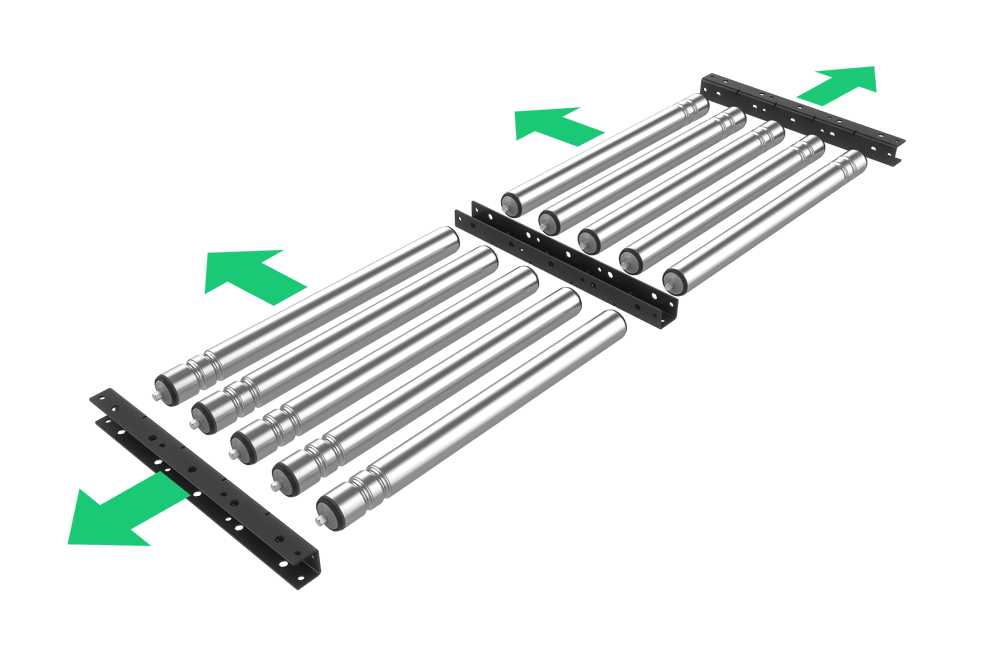
Vention conveyors have modular width capabilities, which means you can increase the scale of any application by adding more rows of rollers to your conveyor. Check out our design library for inspiration.
|  From left to right: gravity, automated, modular |
|
Technical Specifications
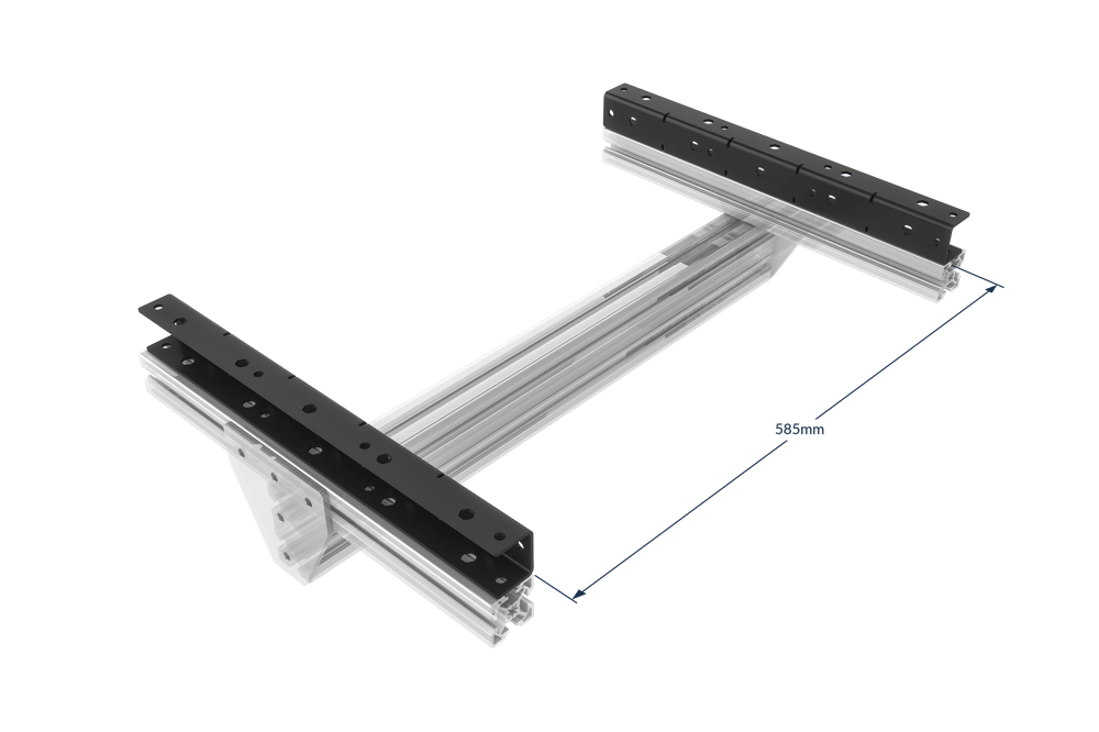
Roller width | 585 mm |
Conveyor width | Modular in 585 mm increments, plus 45 mm per bracket |
Conveyor length | Modular in 450 mm increments |
Max payload per roller | 40 kg |
Max driveable payload per motor | 30 kg |
Max number of rollers powered per motor | 14 (7 on each side of motor mounting block) |
Min object size (length)* | 270 mm |
Max linear speed | 2000 mm/s |
Displacement ratio | 157.7 mm/turn |
Roller material | Zinc-plated steel |
*Intended to ensure that the conveyed object is in contact with at least three rollers, spaced 90 mm apart, at all times
The above rating for maximum driveable payload per motor is calculated at equilibrium and assumes a horizontal conveyor. The limiting factor is slip between the belt and the conveyor roller. To determine the correct powertrain for more complex applications involving accelerations and inclines, see Calculating Required Driving Force
Calculation Required Driving Force
To calculate the required linear force to drive your payload one must consider the desired starting acceleration and the incline of the conveyor. The sum of the forces required to fulfill these specifications will give the required linear force of the roller conveyor.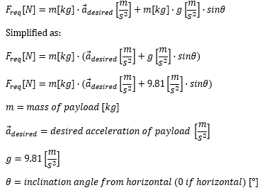
After the required driving force has been calculated, compare it to the force vs speed graph below.
Sample Calculation
Example: A roller conveyor needs to move a payload of 20 kg at 1.0 m/s up a 10 degree incline with seven rollers on each side of the motor mount (14 rollers total). The conveyor must occasionally be able to accelerate the mass at 0.5 m/s².
In this case our variables are 20 kg for mass, 0.5 m/s² for acceleration, and 10 degrees for angle theta.
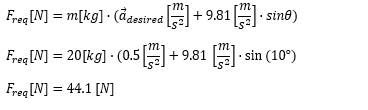
These variables result in a required driving force of 44.1 N with a speed 1000 mm/s.
Looking at the force vs. speed graph below, we can see that the required motors are part numbers MO-SM-011-0000, MO-SM-012-0000, or MO-SM-013-0000, driven by MachineMotion 2.
Force vs. Speed
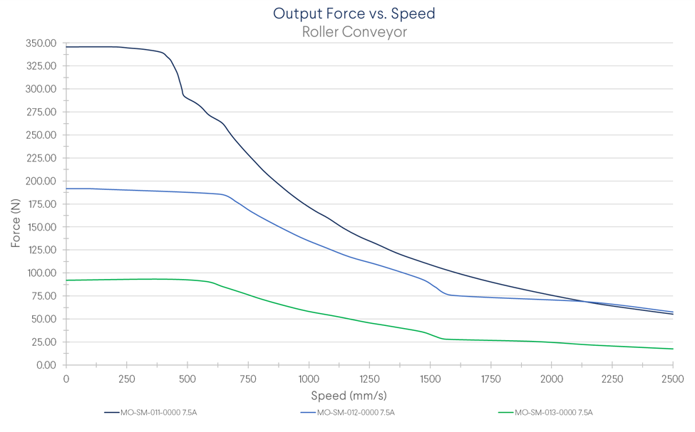 Roller conveyor linear force using Vention's three NEMA 34 motor options, driven by MachineMotion 2. |
Once the motor type has been selected based on required force and speed you can add the appropriate part to your design.
Motor Mounting Block Configurations
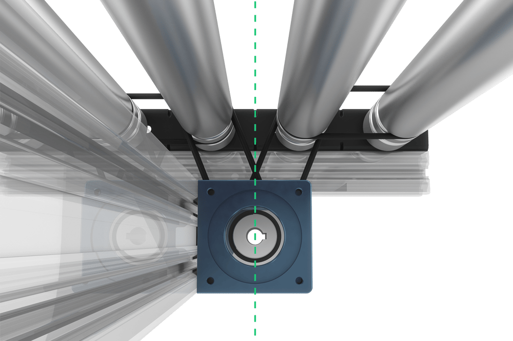
Vention’s motor mounting block (MO-CV-003-0001__2) can be installed on your conveyor frame in three different configurations.
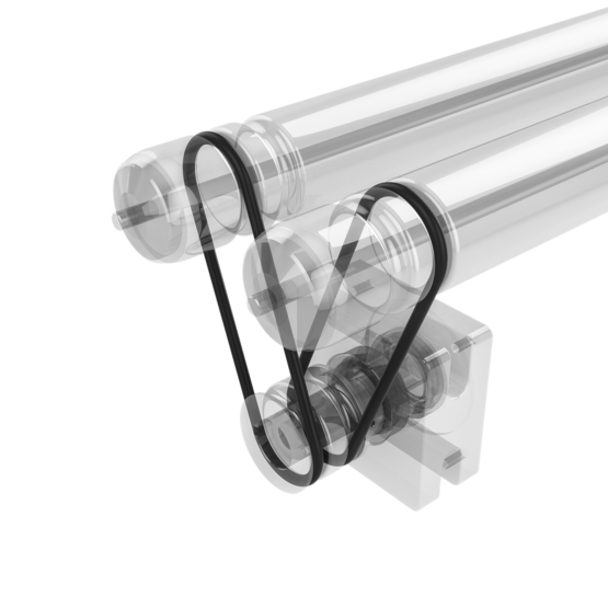
Using two 306-mm belts (MO-PL-002-0306), the motor mounting block can be installed 112.5 mm below the conveyor rollers, in between two consecutive rollers.
Using one 292-mm belt (MO-PL-002-0292), the motor mounting block can be installed 112.5 mm away from a parralel conveyor roller.
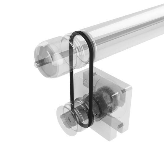
Using one 300-mm belt (MO-PL-002-0300), the motor mounting block can be installed 112.5 mm away from a perpendicular conveyor roller.
Assembly Instructions
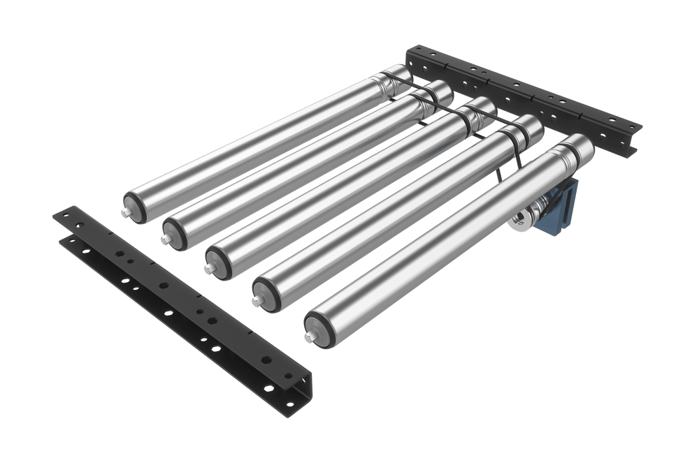
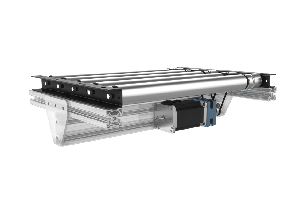
These instructions will help you assemble an automated conveyor coupled to our motors using two of our 306-mm belts (MO-PL-002-0306) and our motor mounting block (MO-RM-003-0001). The motor can then be installed parallel to the rollers and under the conveyor.
If this motor mounting configuration does not fit your application’s space requirements, see the two other motor mounting configurations and the belts that make them possible: MO-PL-002-0292 and MO-PL-002-0300.
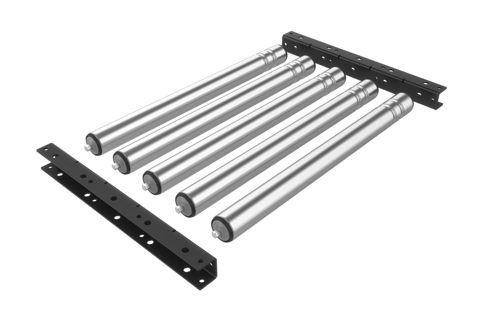
Assemble the vention extrusion frame (see Assembling your Vention machine).
Install each bracket with its flanges set 585 mm apart on the frame, using four screws per bracket.
If building an automated conveyor, install the rollers connected to the motor with their 257-mm belts (MO-PL-002-0257) and 306-mm belts (MO-PL-002-0306) installed but hanging free. If building a gravity conveyor, omit the belts.
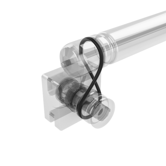
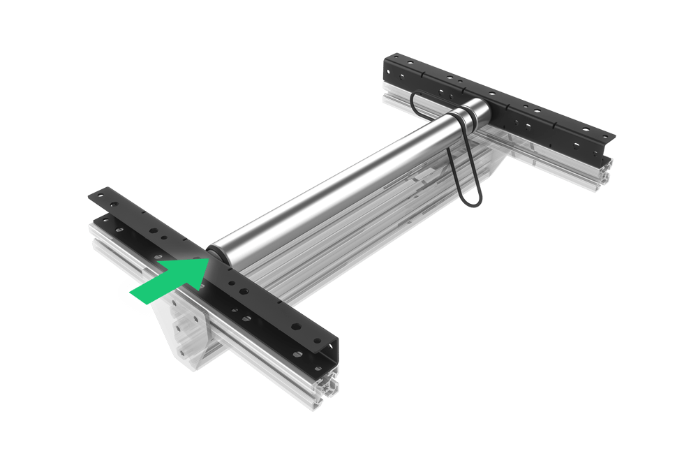
To install the rollers:Insert the fixed end of the shaft
Insert the spring-loaded shaft end while keeping the spring-loaded shaft fully pushed in.
Release the shaft, making sure the spring-loaded end fully engages in the bracket when released.
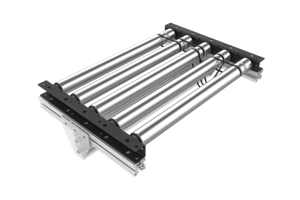
Install the rest of the rollers (the ones not connected to the motor).
Attach a coupling belt and free-hanging belt to the new roller. Loop a new 257-mm coupling belt onto the roller, then connect the roller to the free-hanging belt of a previously installed roller.
Insert the new roller into the bracket, fixed-end first (followed by the spring-loaded end).
Repeat steps 4 a. and b. for each roller. Connect the final roller to the previous roller’s free-hanging 257-mm belt.
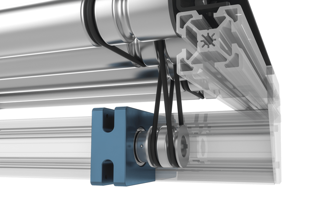
Install the motor mount. Center its shaft between the two rollers that connect directly to it.
Align the pulley with the roller’s grooves as best as possible. Connect the two rollers to the motor mount using the two free-hanging 306-mm belts. The belts can stretch to accommodate minor misalignment.
Install your Vention NEMA 34 motor on the motor mount.
Note: when installing motors, apply a small amount of grease to the motor shaft so that it is lightly coated. This will reduce the possibility of fretting corrosion occurring during operation, making future removal easier.
Your conveyor is now ready to automate!
|
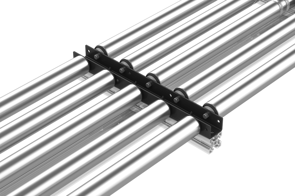
N-Row Conveyors
If your conveyor has more than one row of rollers, make sure you install the center brackets as shown in the assembly below. Keep the center bracket’s side flanges pointing up to create a U shape.
|
Maintenance
To take the roller apart for maintenance, first disconnect the spring-loaded end of the roller, then disconnect the fixed end and remove the roller. Next, remove the belts. Then follow step 3 or 4 in the assembly instructions above as needed.