General Description
The Vention Machine Tending Hardware Kits are designed to optimize the loading and unloading of machine tools with a standardized and cost-effective robot base. Select from two different bases, safety area scanners, supporting add-ons and Vention’s extensive library of grippers to tailor this kit to your specific needs. Due to their large storage capacity, both the drawer base and part presenter base have the ability to extend the autonomy of a CNC machine tool to over 8 hours. Tested to work with Universal Robots, FANUC and ABB cobots, this kit is flexible and powerful. Unlock your CNC’s full potential with one of Vention’s Machine Tending Hardware Kits.
Available Configurations
Two bases are available for customization, the drawer base and the part presenter base (coming soon!).
Base Type | Maximum Workpiece Height | Total Area Available for Part Storage | Additional Features | |
|---|---|---|---|---|
Drawer Base | 170 mm | Up to 1.45 m2 | DIN mounting for PLCs, pneumatics ready, CNC communication ready, safety area scanner ready, 4x drawer position sensors | |
Part Presenter Base | TBA | TBA | Pneumatics ready, CNC communication ready, safety area scanner ready, storage shelf |


Design
Supported Robot Arms
Manufacturer | Models |
|---|---|
Universal Robots | UR10e, UR20, UR30 |
ABB | ABB CRB15000 GoFa10, ABB CRB15000 GoFa12 |
FANUC | FANUC CRX-10iA, FANUC CRX-10iA/L, FANUC CRX-20iA/L |
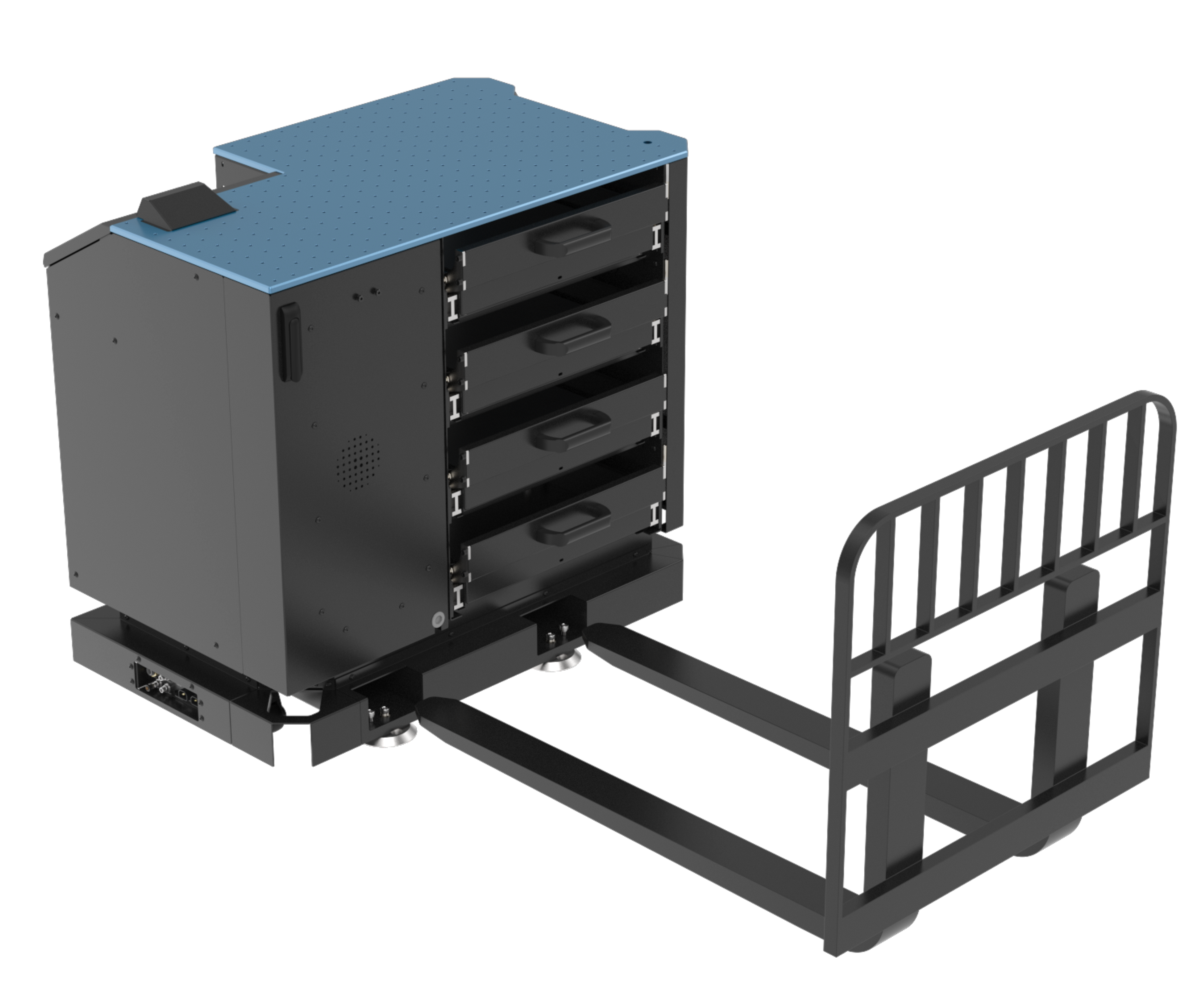
Drawer Base Component Overview
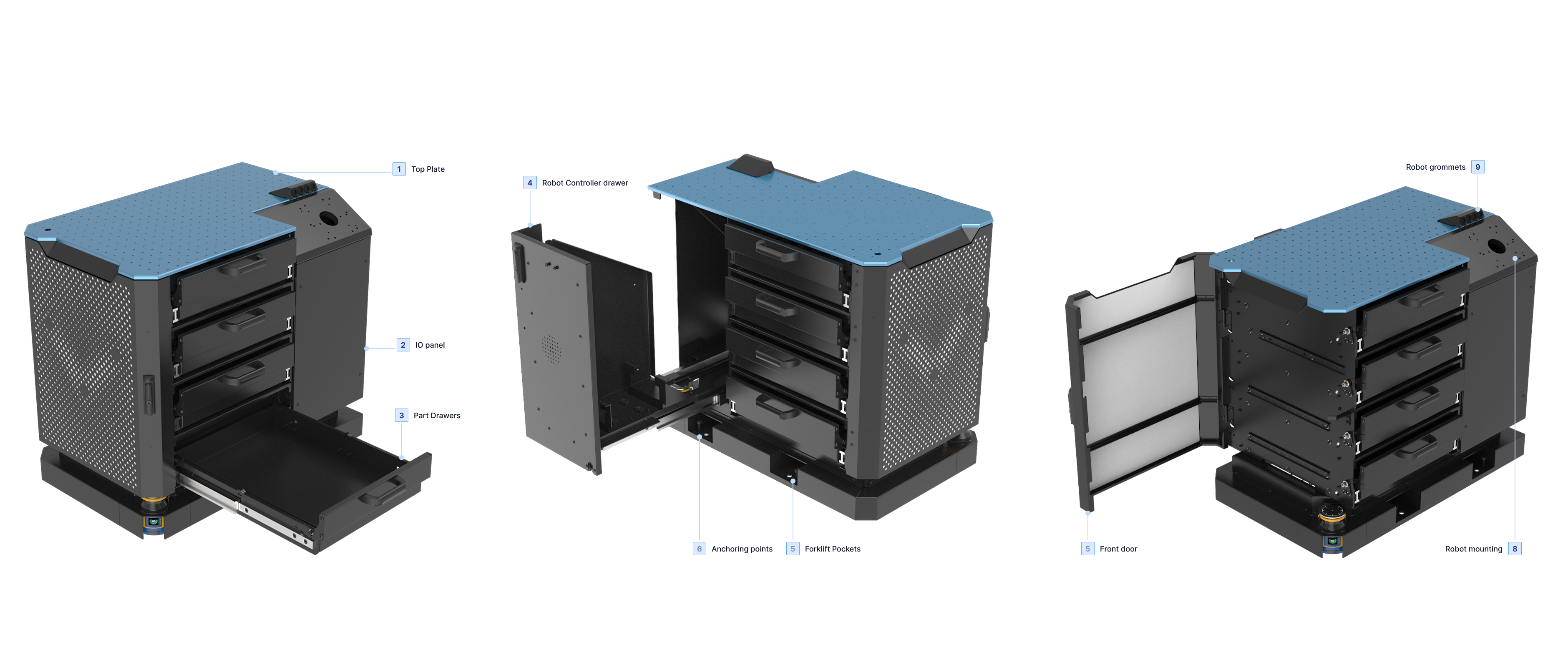
Machine Tending Drawer base overview
Top plate: The top plate enables the mounting of custom jigs, tool changers or other accessories via its array of M8 × 1.25 threaded holes.
IO panel: Located on the CNC side of the base, these IO allow the base to be quickly connected to power, pneumatics and CNC communication.
Part drawers: Four part drawers give this base its ability to store part blanks. Use the optional part trays to position parts accurately and repeatably.
Robot controller drawer: The robot controller is mounted in this drawer, which provides easy access during commissioning and troubleshooting. Its also has threaded holes for a pendant mount.
Forklift pockets: Integrated into the machine frame are two forklift pockets. Use these to easily lift the base.
Anchoring points: The base is provisioned with four 19mm holes for floor anchoring and four M12 leveling screws.
Front door: Behind this door are three DIN rails which can be used to mount customer PLCs or pneumatic components.
Robot mounting: The robot mounting plate allows the mounting of the supported robots directly. Dowel pins ensure repeatable mounting.
Robot grommets: Four cut to size grommets allow users to pass pneumatics, sensor cables and robot cables from the inside of the base to the robot base flange.
Inputs, Outputs & Pinouts
To enable a customizable solution, the Machine Tending bases are provisioned with an IO panel consisting of the following:
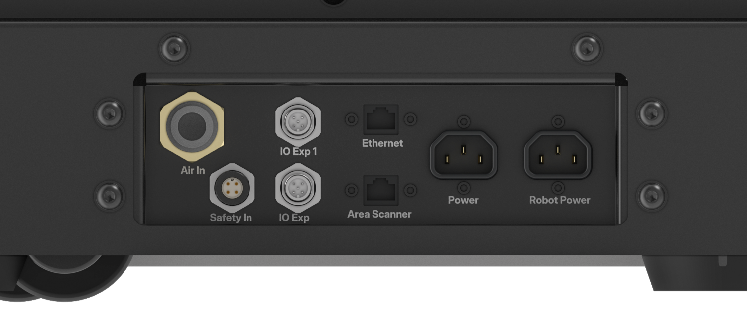
Machine Tending IO panel
Two AC power connectors: One connector is used by default for robot controller power, second can be used to connect to user provided PLC.
Two M12 8 pin connectors: These are user wire-able to enable communication between the robot controller and CNC if required. See pinout below.
Two RJ45 ports: One is used to connect a laptop to the area scanners (if purchased) for programming. The second can be used to connect to user provided PLC or for other user configured communication.
One M12 12 pin connector: Used when the safety area scanner add on is purchased to connect an external estop module to the base.
One 12mm pneumatic fitting: Can be used to power pneumatic components added to base, including grippers if configured.

User wire-able M12 connector pinout
Sample Floorplan
The exact configuration of Machine Tending base and CNC machine will depend on the users requirements. However, a sample floor plan is shown before to illustrate a common setup.
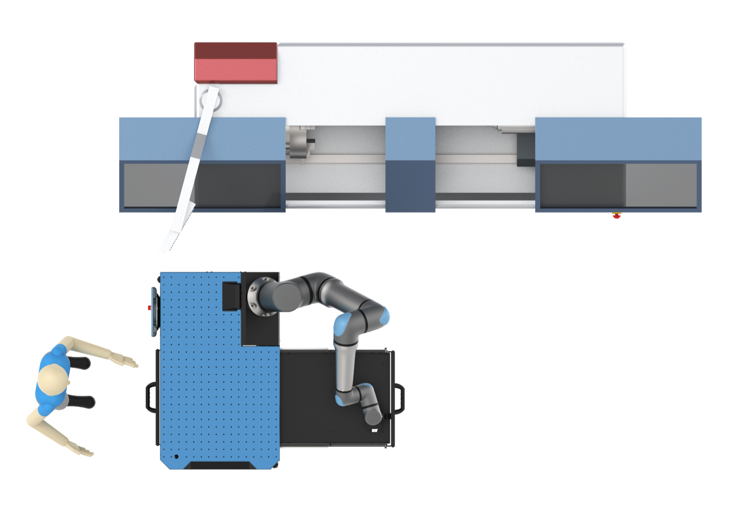
Drawer base floor plan
Specifications
Drawer Base | Part Presenter Base | |
|---|---|---|
Machine Weight | xxx kg | TBA |
Footprint | A x B m | TBA |
Useable storage area | Up to 1.45 m2 | TBA |
Maximum part dimensions | TBA | |
Load Capacity | 100 kg per drawer | TBA |
Operating temperature range | 10 -40 °C | 10 -40 °C |
Maximum operating humidity | 85% | 85% |
Power requirements | Up to 15A @ 120V or 10A @ 240V (Robot model dependent) | Up to 15A @ 120V or 10A @ 240V (Robot model dependent) |
Mounting requirements | Anchored into concrete or transfer plate | Anchored into concrete or transfer plate |
Drawer repeatability | ±0.05mm Drawer Position | N/A |
Drawer rigidity (deflection) | 1.35 mm / 20 kg | N/A |
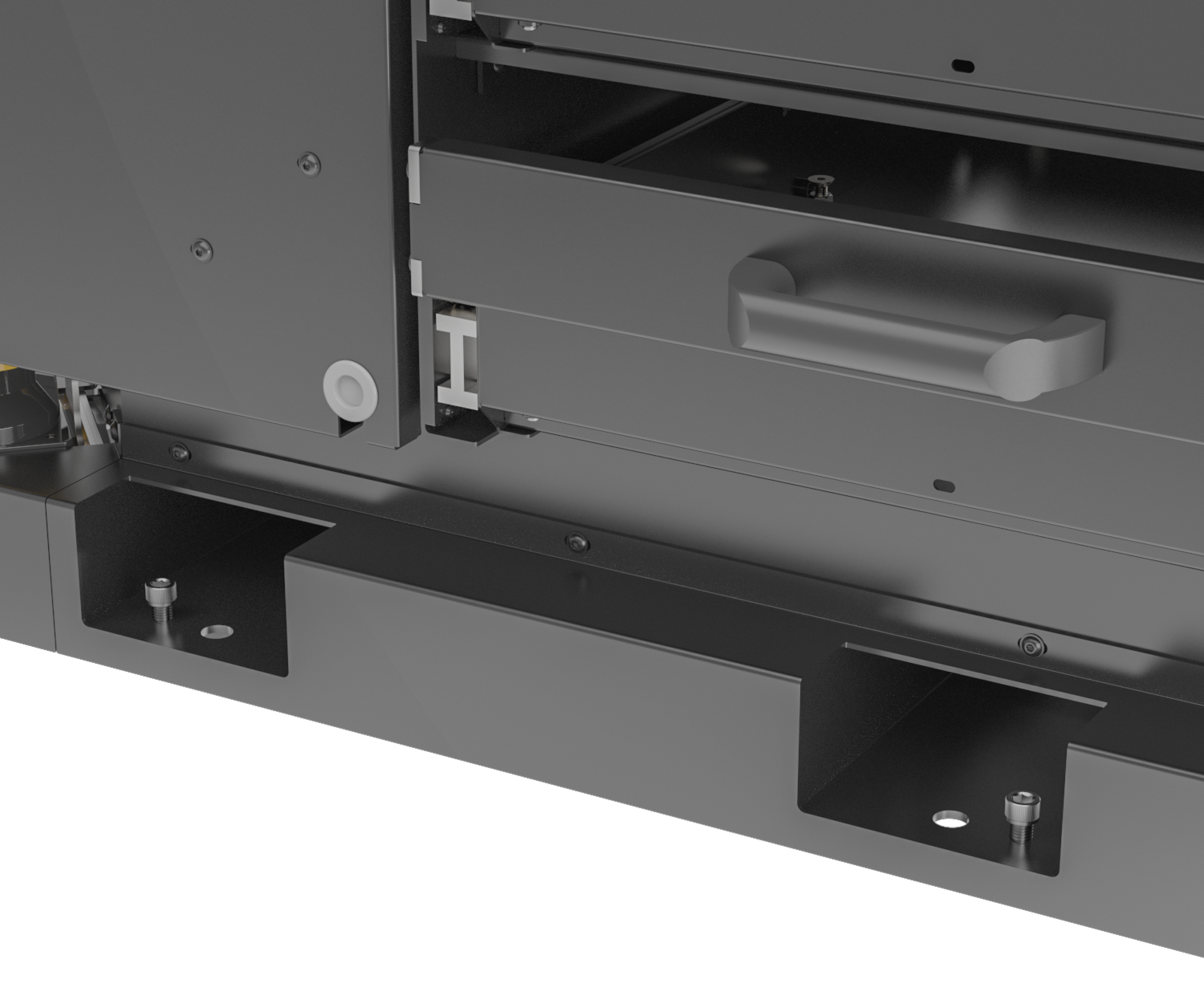
Drawer Mechanism
Function
Machine Tending bases equipped with the drawer option included a locking mechanism to properly fix the drawer in the closed and open positions. This is ideal for robots, as it eliminates the risk of the drawer being in an undefined position. The drawer has the ability to be locked in three positions: closed, open on the robot side and open on the operator side. To unlock the drawer, the robot or operator simply lifts the handle approximately 10mm to release it from the pins. The drawer is then free to slide in either direction. Drawer can be unlocked from either the robot or operator side.
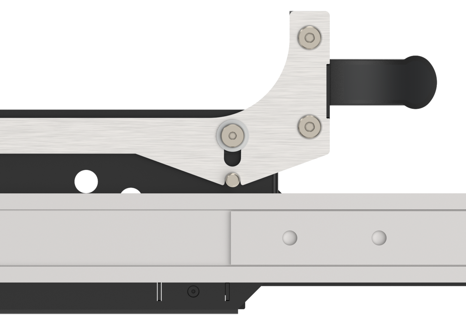
Drawer locking mechanism
To validate that the drawer is in a defined position, each drawer has two inductive proximity sensors; on each side of the drawer (operator and robot sides). The two sensors defines 3 states for the drawer: closed, opened in the operator side and open on the robot side. Users can use this in their programs to check drawer state and eliminate the risk of the robot unintentionally touching a partially open drawer.
.png)
Drawer sensor location
Robot Interaction
To successfully program a cobot to open the drawer an optional hook can be purchased. Generally the motion of the robot to open or close the drawer can be broken down into these steps:
Approach the robot end of arm tool near the handle.
Position the hook or gripper directly under the handle.
Lift the handle to a point where the locking mechanism is disengaged.
Open or close the drawer.
Release and clear the end of arm tool.
Check that the drawer sensor is triggered.
.png)
Drawer opening sequence
Drawer Sensors
Drawer sensors are inductive type M18 NPN, when the drawer is in a defined position they will be triggered by a bolt on the drawer. It is possible to adjust them both in the direction of drawer travel and perpendicular to ensure they are triggering correctly. This adjustment is done at the factory and should not be required on receiving.
Inclusions & Options
Safety Area Scanner Kit
The safety kit comes pre-wired into the Machine Tending base. Area scanners enable the Machine Tending unit to sense approaching humans and affect robot behavior as result. Users have the ability to configure this behavior, the size and dimensions of the zones through the Datalogic programming interface. Learn more by reading Vention’s manual.
.png)
Laser Scanner in the Machine Tending Base
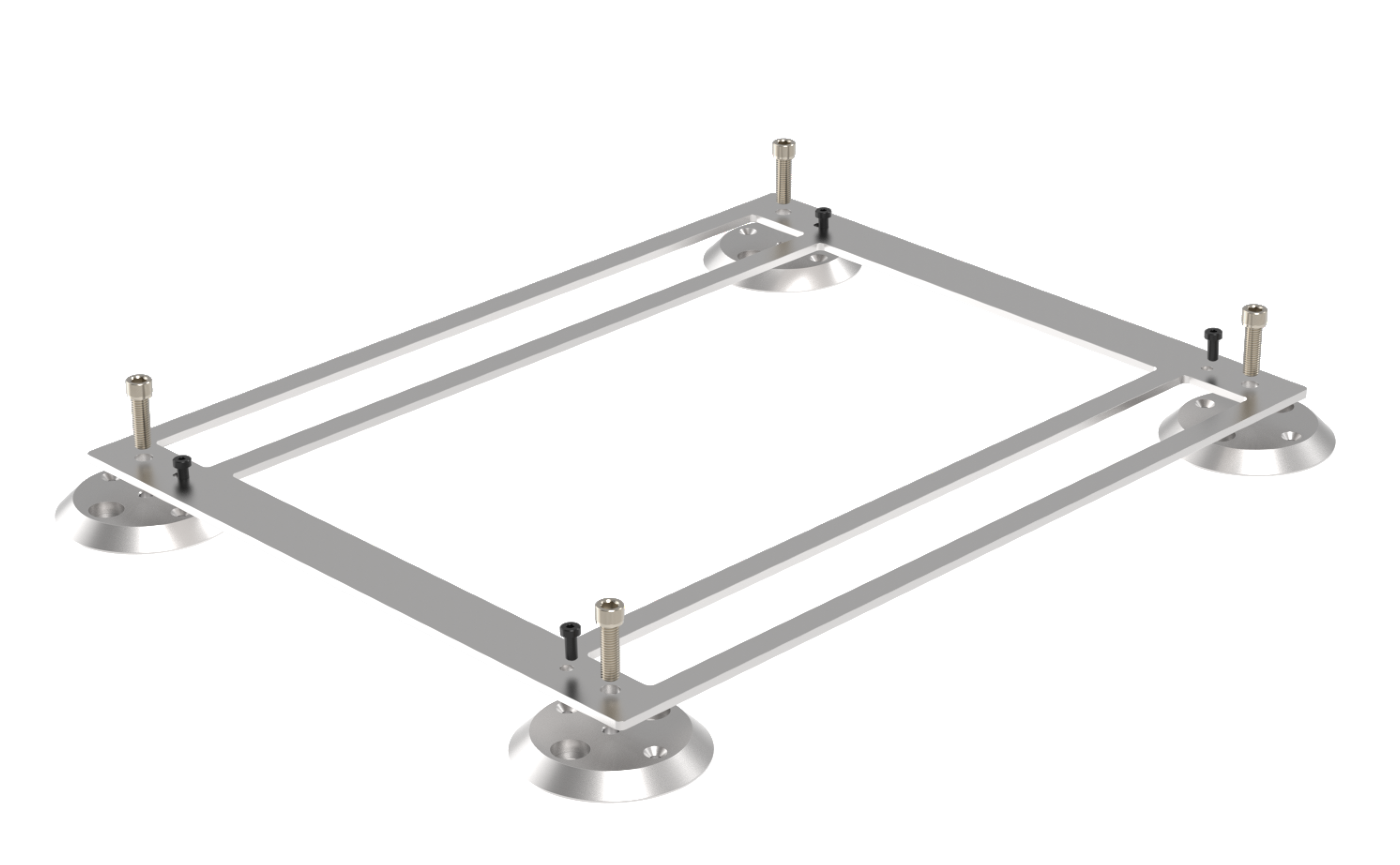
Floor Anchor Kit
Included with every Machine Tending base is a drill jig that can be used to drill anchors in the correct location. See the installation instructions below. The floor anchoring kit is an optional extra that allows quick anchoring of the machine tending base. Once the anchor pads are installed, the machine tending base can be moved into position, bolted down and leveled all within 10 minutes. Anchor pads can be installed at each machine that will be tended, allowing flexible use of one or more machine tending bases.
.png)
Floor mounting pads
Part Tray
Customized part trays are available for both drawer and part presenter bases. Vention will customize these part trays for user parts, or blank trays can be purchased for users to machine themselves. Trays are made from 3/8” thick PolyEco, an impact resistant, recycled HDPE.
.png)
Blank Part Tray Customized Part Tray
Part Tray Stand-off Kits
For longer parts, stand-off kits can be added to the design to space the trays. Stand-off kits come in two lengths, 25 mm and 50 mm and can be stacked together if needed. These are needed for longer parts since without them those parts would have a tendency to fall over.
.png)
Stand-off kit exploded view
Drawer Opening Hook
To aid with drawer opening and closing, the drawer opening hook and adapter are available from Vention. The modular multi-tool flange adapter is designed for all cobots and grippers that Vention offers. It can be combined with the hook in a variety of ways to suite your application. See its technical documentation for more information.
Pneumatics
Vention offers a variety of pneumatic components to customize your Machine Tending solution. Add an air-prep station and solenoid valves to support a pneumatic gripper or air blow system. The base includes a 12mm fitting at the bulkhead and internally routed tube to make customization simple and quick.
Design Checklist
To make your machine tending application successful we recommend going through the following checks.
Reach Validations
Robot reach is critical when selecting the cobot model needed for an application. Also, ensure that the weight of the workpiece, tool flange and gripper does not exceed the maximum capacity of the cobot arm.
Opening Bottom Drawer
Opening the bottom drawer typically presents the largest challenge to reach with the machine tending drawer base. Check that the robot reach is sufficient to clear the handle of the bottom most drawer. This has been confirmed to work with the UR10 when equipped with the drawer opening hook. Other robots, grippers and tool flange accessories might affect this reach, so it is important to check.
Part Blanks
For each part blank that will go on a part presenter base or drawer base, it will be necessary to check the following:
Part to part spacing is adequate to allow the gripper fingers to go between the workpieces.
Robot has the reach to pull the part blanks out of the grid or part tray. Remember that the longer a piece, the more the robot will have to move to clear the work holding.
CNC Validation
In order to place a part into a CNC, the path of the robot tool and workpiece into the CNC machine must be considered. CNC door size, interior volume and tools can affect the path of the robot to pick and place workpieces.
Interference
Ground
In some extreme cases, its possible that when reaching to open the bottom most drawer the gripper touches the ground. This is only the case when either a long wrist extension is used or a gripper with large tool center point offset is used. In this case, it is important to check that there is no collision with the ground. An extended drawer opening hook is available to mitigate this issue.
.png)
Available extended Drawer opening hooks
Handles
On the second, third and fourth drawers the handle from the previous drawer project slightly over the tray area. Check that the tool and robot end of arm flange do not interfere with these handles.
.png)
Robot EOAT interference with handle
Lifting
Before installation of the Machine Tending base, it is required to lift it off the shipping pallet. Two methods are available for lifting the base, first with the built in forklift pockets and secondly by lifting from the top plate threaded holes. Before lifting, ensure that the strapping has been cut and the wrapping removed. Also ensure that the drawers are in the closed locked position for the drawer base. Both methods of lifting are covered below. Ensure that local regulations for lifting are followed.
Lifting with a Forklift
Two lifting pockets are available for lifting, their location and dimensions can be found on the drawing of the base. Before lifting, ensure that the levelling screws are removed and that no wires/cables will get pinched. Make sure that your forklift is capable of lifting at least 500kg.
Forklift pockets
Lifting using hooks
It is equally possible to lift the Machine Tending base with lifting hooks. Vention suggests using M8 threaded hooks that are rated for lifting, such as these that are available on the marketplace. Depending on which robot arm is selected, different holes and lifting straps may be required to lift the load without tipping.
.png)
Lifting with straps
Installation
As the Machine tending kit is mounted on wheels, ensure the cart is anchored before mounting the robot on the top plate during the installation at your factory.
Anchoring with Included Drill Jig
In order to maintain repeatability when placing parts in the CNC machine, it is required to anchor the base to the ground. Included with every base is a drill jig to space the anchors properly to match the bolt holes in the base. The steps to use this jig are as follows:
Place the machine tending base in the desired position and verify the reach of the cobot into the CNC machine.
Mark the location of at least two anchors with a marker.
Move the Machine Tending base out of the way and place the jig over the marked position.
Drill the floor according to the anchoring manufacturers specifications.
Re-place the Machine Tending base and level using the included levelling screws.
Leveling the Machine Tending base
Fasten with concrete fasteners.
Anchoring with Optional Floor Kit
Place the machine tending base in the desired position and verify the reach of the cobot into the CNC machine.
Mark the location of at least two anchors with a marker.
Move the Machine Tending base out of the way.
Assemble the jig and floor pads together, place over the marked locations.
Floor kit anchoring kit assembly for drilling
Drill and anchor the four available holes, remove jig to drill and anchor the other four if required.
Place base over the pads and level the base, then tighten the anchoring fasteners.
.png)
Floor kit anchoring kit levelling and fastening.
CNC Communication
Communication with the CNC is critical to successfully deploying a machine tending application. Communication will tell the robot when the CNC is ready for a new part to be loaded and the CNC when to release the part to the robot. The following is a list of potential signals that might be used for communication. Each application will need to have its own communication requirements defined.
Signals from CNC to cobot controller:
Work-holding status (clamped/unclamped)
Secondary work-holding status (clamped/unclamped)
Cycle complete and ready for robot unloading
Door open/closed
Estop
Signals from cobot controller to CNC:
Door open/close request
Work holding request to open/close
Secondary work holding request to open/close
Cycle start
Estop
Possible communication methods include:
Digital signals directly from robot to CNC
Communication over EtherNet/IP, Modbus TCP or PROFINET depending on CNC machine capabilities