Overview
MachineMotion AI is an advanced industrial automation controller, designed to power the next generation of motion control and AI-driven automation. It integrates NVIDIA technology to facilitate AI-enabled and autonomous robotic applications. MachineMotion AI supports up to 20 motors via EtherCAT, offers plug-and-play connectivity with a broad ecosystem of automation components, includes built-in networking, safety, and I/O expansion capabilities.
This document covers requirements for current version of MachineMotion controller. For previous version, refer to link below:
This user manual covers the following MachineMotion AI controllers:
Controller | Description |
|---|---|
| MachineMotion AI Pro CE-CL-031-3000 |
| MachineMotion AI CE-CL-030-1500 |
| CE-CL-030-0000 MachineMotion AI Robot |
| CE-CL-031-0000 MachineMotion AI Robot Pro |

.png)
.png)
MachineMotion AI Key Features
AI-Powered Automation: Equipped with NVIDIA Orin NX16GB / Orin Nano 8GB processors for AI-driven robotics and machine vision applications.
EtherCAT Connectivity: Support up to 20 motors via EtherCAT daisy-chaining of motors.
Integrated Safety System: Dedicated ports for safety HMI, robot safety and child devices.
Expanded I/O Support: 2x RS485 ports, supporting up to 128 sensors, and EtherCAT-compatible IO-Link Masters.
Built-in Networking: 2x Gigabit Ethernet, Wi-Fi, and LTE connectivity for seamless remote monitoring and OTA updates.
Camera Integration: PoE live camera and PoE vision camera support.
Higher Power Capacity: Upto 3,380W total power, with upto 3,000W motion output with MachineMotion AI Pro.
Cloud-Connected Security: TLS 1.2 & 1.3 encryption for secure remote access.
Linux-Based OS: Compatible with Python, G-code, and MachineLogic programming interfaces.
IP54 Industrial Enclosure: Ensures durability in industrial environments with passive or fan-assisted cooling.
Status Light: Integrated in MachineMotion AI controller and motors for quick diagnostics
What is Included with Each MachineMotion AI
Each MachineMotion AI package includes:
MachineMotion AI Controller
AC Power Cord
120V - NEMA 5-20 - CE-CA-001-0007
240V - CEE 7/7 - CE-CA-001-0008
240V - NEMA L6-20 - CE-CA-001-0009
Ethernet Cable - CE-CA-017-2130
USB 3.0 To Gigabit Ethernet Adapter - CE-EL-005-0002
Safety Jumpers - CE-SA-102-0001
Mounting Hardware - CE-HW-005-0000
Safety Notice
Introduction
This section contains important information pertaining to the safe installation and operation of the MachineMotion AI controller. The end users are required to familiarize themselves with this section and have a good understanding of the installation, manipulation and operation of the MachineMotion AI controller.
It is mandatory to follow all assembly instructions and guidance provided within this manual while attributing special emphasis to this section.
Throughout this manual, special attention shall be provided to areas identified by the warning symbols below. Here is a description of each symbol used in this manual as well as symbols used on any Vention product. Vention aims to use standard symbols as defined by ISO.
Symbol | Definition |
|---|---|
| Warning/Caution: Electric Shock Hazard Dangerously high voltage; avoid coming into contact with any such electrical parts. Failure to do so may result in serious injury or death. |
| Warning/Caution: Hot Surface This symbol is used to indicate that a surface might become too hot to touch. The user should avoid touching any surfaces marked with this symbol. Not doing so might result in serious injury. |
| Warning/Caution: General Warning This symbol defines a general warning. The user should take care regarding the hazard specified by the supplementary sign or accompanying text. Not doing so might result in serious injury or death. |
| Warning/Caution: Pinch-Point Warning This symbol indicates the presence of a pinchpoint. The user should take special precautions when accessing these areas and ensure that the machine is not moving. Not doing so might result in serious injury or death. |
| Instruction: STOP This symbol emphasises that the user must stop and carefully read the specified instruction before continuing. |
| Mandatory instruction: Refer to Instructions This symbol is used to indicate that it is mandatory to refer to the instruction manual before proceeding. |
.png)
.png)


![]() NOTE
NOTE
Vention disclaims all liability if the MachineMotion controller is damaged, changed, or altered in any way not indicated in this manual. Vention cannot be held responsible for damage caused by incorrect manipulation, installation, operation, or programming of the MachineMotion controller. Although this manual aims to reduce the risks associated with operating the MachineMotion controller, it cannot guarantee their complete elimination. As such, Vention should not be held responsible for any injury caused by residual risk factors.
User Responsility
This manual only contains information on safely installing and operating the MachineMotion controller. It does not cover designing, installing, or operating a complete machine. The complete machine must be designed in accordance with local safety requirements and standards. The system integrator is responsible for taking all precautions in order to mitigate any potentially hazardous situations in the complete assembly.
These precautions include, but are not limited to:
Performing a risk assessment of the complete system.
Ensuring there is a safety system in place.
Deciding if additional safety devices are needed for the safe operation of the system.
Familiarizing oneself with all relevant literature.
Following all instructions on installing and commissioning Vention products.
Validating the complete system.
Collecting all pertinent information and storing it in a master file accessible to all operators.
Training all potential users.
General Warning and Cautions
This section gives a summary of general warnings and cautions pertaining to the safe manipulation, installation and operation of the MachineMotion controller.
![]() WARNING
WARNING
Upon receiving the MachineMotion controller and its associated components, inspect them for any damagethat may have been incurred during shipping.
Read all related documents before using the MachineMotion controller.
Ensure that all associated components (see “Included with MachineMotion”) are in the box.
Follow the installation guidelines provided in this manual.
Ensure sufficient power is provided to the MachineMotion controller
Before powering on the system, make sure all connectors are firmly attached.
Never use a damaged MachineMotion controller.
Do not open the MachineMotion AI controller. Contact Vention Support.
While performing the initial validation of the complete system, use low speeds (maximum 50 mm/s).
Before attaching any Vention accessory or module to the MachineMotion controller, read its respective user manual.
Do not connect or disconnect any device from the controller while powered on.
Always use the power button to power off the controller. Wait for the status LED to turn off before disconnecting the power cable.
Intended Use
MachineMotion is a smart multi-axis controller. In conjunction with Vention actuators, modules and other auxiliary devices, it is used to build complex automated systems. The MachineMotion controller itself is tested and certified to various applicable standards pertaining to electrical safety. However, that does not mean any given machine will be inherently safe. The integrator is always responsible for creating a safe design. We recommend using ISO 12100 and RIA R15.306 when the machine includes a robot to perform a risk assessment.
Carry out risk assessments when designing the machine. The risk assessment should determine the need for additional safety measures during all operative scenarios of the complete machine.
![]() WARNING
WARNING
MachineBuilder is a complete 3D-CAD platform that allows users to quickly design complex automation solutions. It needs to be noted that safe design principles and techniques are to be considered by the user. Although the MachineMotion controller is thoroughly tested and certified to international electrical safety standards, the end user is responsible for the safe installation of Vention’s products. To ensure safe operations of Vention products, it is required to perform a risk assessment before the installation and deployment of any Vention designed machine.
Before proceeding with the unboxing, installation and deployment of any Vention machine, the end user is required to read this manual. At all times, Vention’s Terms and Conditions should be respected. Vention Terms and Conditions, available at www.vention.io/terms-of-use
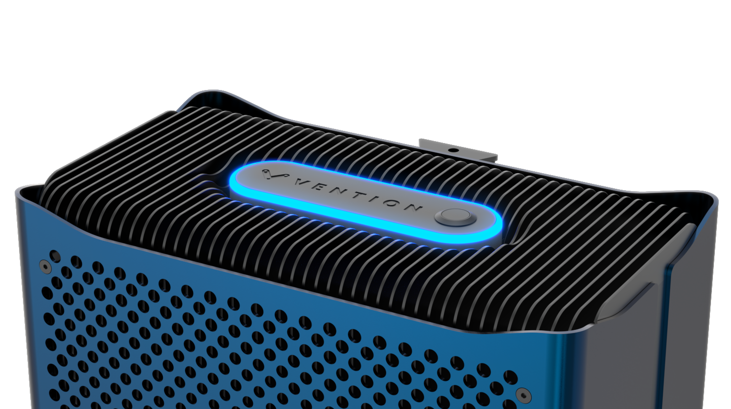
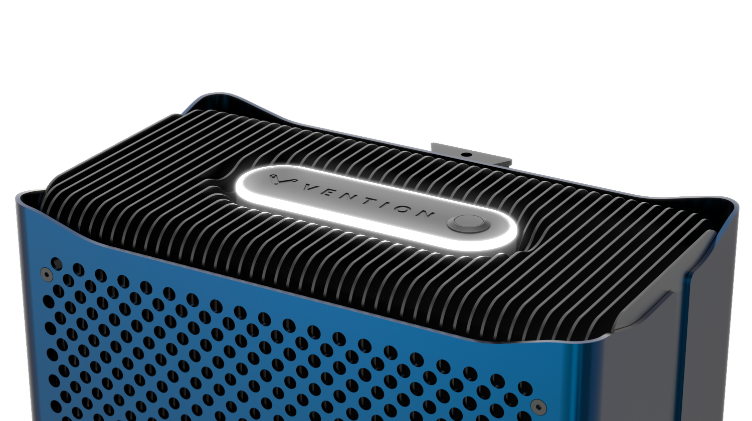
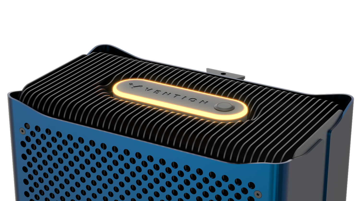
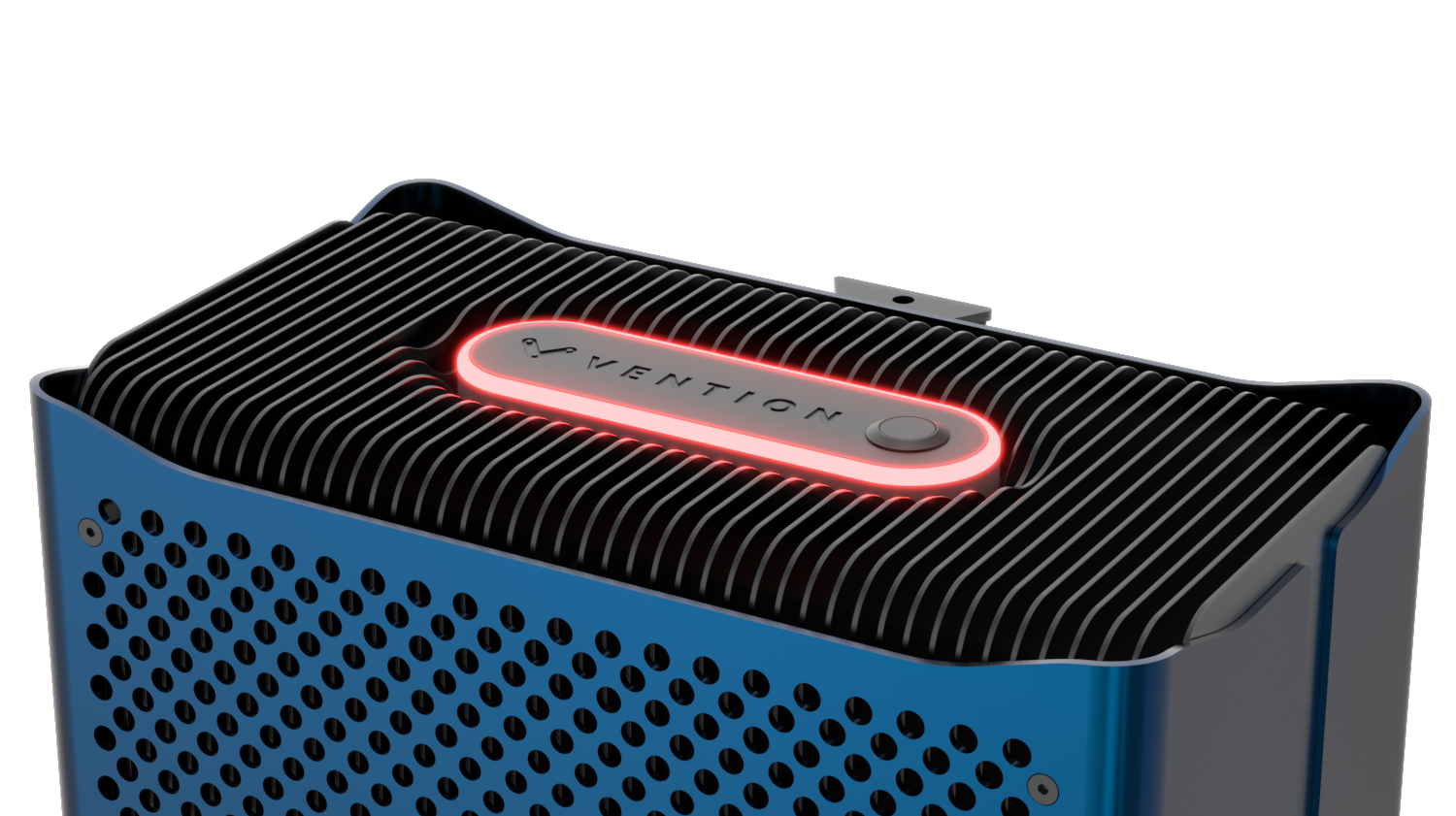
Status LED
The status LED on top of the MachineMotion AI controller indicates system states:
Status LED | LED Behavior | Controller State | Controller State Description |
|---|---|---|---|
| Off | Off | Machine is off |
| Pulsing Blue | Booting or Shutting down | Machine is booting or machine is shutting down |
| White | Idle | Machine is on and operational |
| Yellow | Non-operational | Machine is on and non-operational |
| Red | Emergency Stop | Machine is on and in emergency stop |
| Pulsing White | Running | Machine is on and a MachineLogic application is running |
.png)
.png)
Power Button
The MachineMotion AI controller power button is located at the top of the enclosure, next to the status LED.
.png)
Mounting
Install the mounting bracket (CE-HW-005-1002) to the extrusion with the screws provided (HW-FN-003-0018). Install the MachineMotion AI controller onto the mounting bracket and secure the controller with 2 screws (HW-FN-003-0018) illustrated below.
|
|
.png)
.png)
Wiring Diagram
![]() NOTE
NOTE
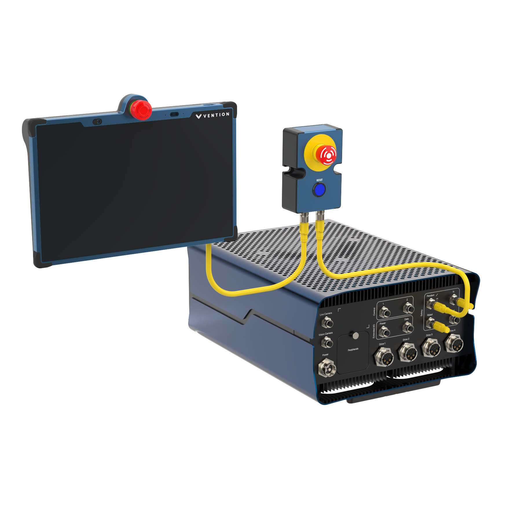
A Pendant or E-Stop module must always be connected to the Pendant / E-Stop port. If the Robot or Safety IN ports are not in use, a safety jumper (CE-SA-102-0001) must be connected to the port. The Safety OUT port does not require a jumper if unused.
Example | Wiring Diagram |
|---|---|
MachineMotion AI with an E-Stop & Pendant |
|
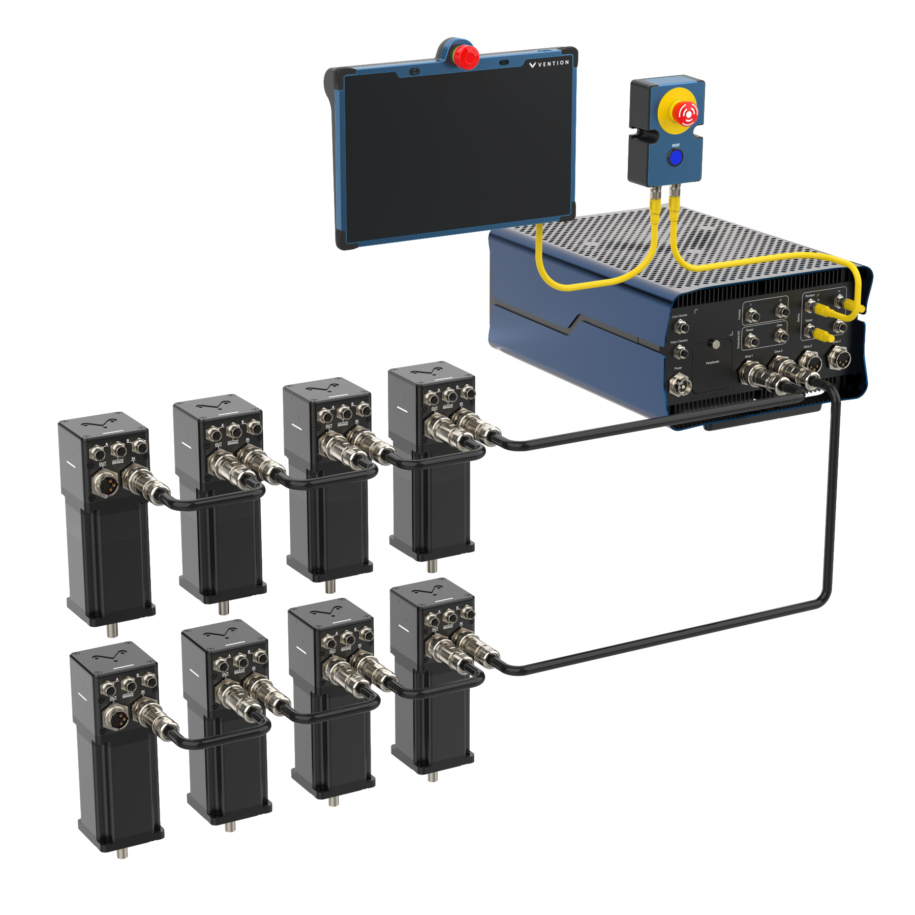
MachineMotion AI with Motors |
|
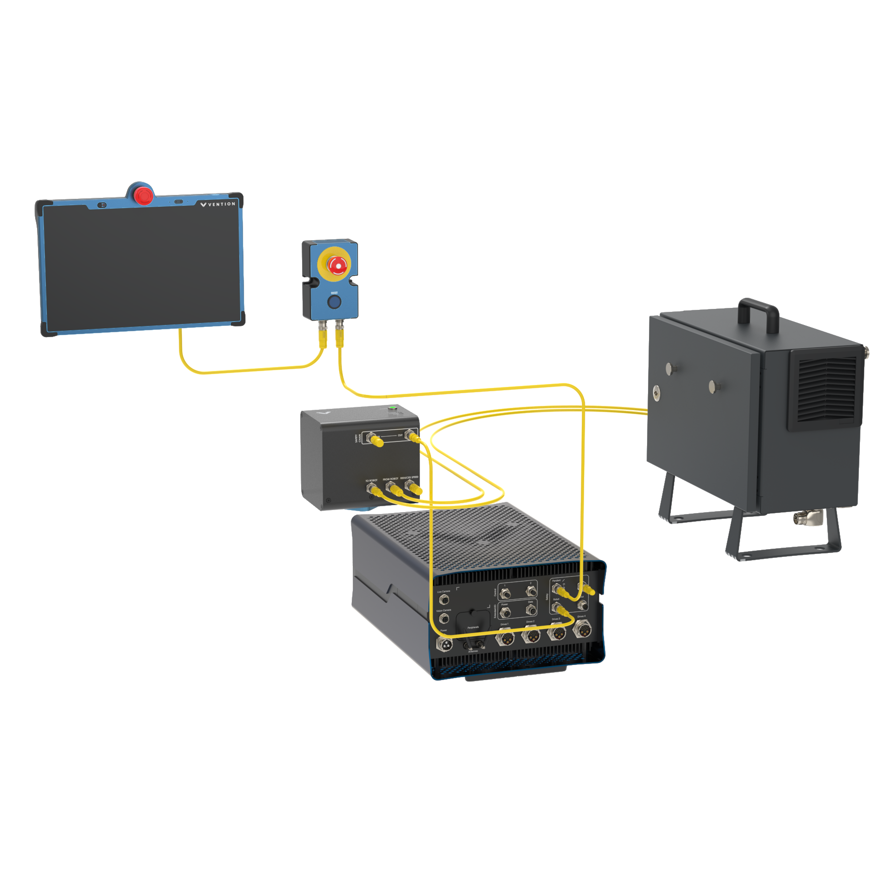
MachineMotion AI with Light Curtains & Area Scanner |
|
MachineMotion AI with a Robot Controller |
|
.png)
Motor Daisy Chaining Guidelines
|
|---|
Important Note
Before connecting or disconnecting a motor from the MachineMotion controller, make sure to power off the MachineMotion controller.
When motors are being daisy chained, your system will experience a voltage drop on each motor cable that corresponds to the overall current draw of the downstream motors. The motor drive will operate correctly as long as its motion supply voltage stays above 60V when no brake is used. When a brake is used, the motion supply voltage must remain above 67V. It is essential to recognize that the actual voltage can vary over time due to the instantaneous current draw of the motors. Additionally, it is crucial to limit the total cable length and the distance between motors to facilitate reliable EtherCAT communication and maintain the drive logic supply voltage above an acceptable level. Therefore, please ensure compliance with the following daisy chaining guidelines.
![]() WARNING
WARNING
Voltage Requirements & Limitations
Please refer to Machine Motion AI Motors & Brake Datasheet for voltage requirements and daisy chanining limitiations
If a motor does not have a brake, make sure it gets at least 60V.
If a motor has a brake, it needs at least 67V.
Cable, Motor & Brake Limitations
The cable between any two motors should not be longer than 50 meters.
The total length of all the cables in one chain should not go over 100 meters.
You can connect up to 10 motors in one daisy chain.
If one of your motors has a brake, it should be no farther than the 6th motor in the chain.
Maximum amount of motors connected to any controller is limited to 20 motors.
Combined power of sensors plugged into Motor Sensor Port and Motor Drive Control Power should not exceed 90W. Refer to MachineMotion AI Datasheet for further information.
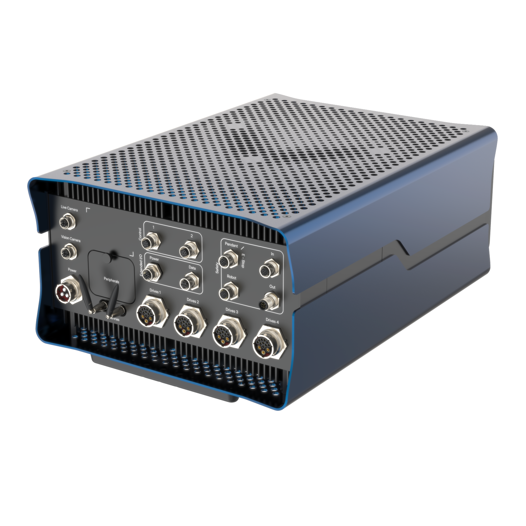
Connecting Components
Power | Input Mains Power (see datasheet/nameplate for voltage rating) |
Drives 1, Drives 2 (AI and AI Pro) | Motors |
Pendant / E-Stop | Pendant |
Pendant / E-Stop | E-Stop Module Interlocks (non-lockable) |
Safety In | Safety Module with Muting Access Request Module |
Robot | Robot Safety Module |
Safety Out | Child Safety Devices |
Control 1, Control 2 | Digital I/O Modules |
LAN | Local network |
To PC | Computer |
USB 3.0 Type-A, USB Type-C | USB devices |
Live Camera, Vision Camera | Camera (PoE) |
To PC should only be used for a direct connection to a computer. Live Camera, Vision Camera, Control, and Safety should only be used with compatible devices. These Ethernet ports are not intended for connection to an untrusted network.
Network Connectivity
MachineMotion AI provides multiple network options:
LAN: Connect the MachineMotion to a local area network via the LAN Ethernet port. Configure the interface via the Control Center.
Wi-Fi: Connect the MachineMotion to a Wi-Fi network via the Control Center.
LTE: Requires an activated SIM card. See Data Bundle subscription page.
Peer-to-Peer Ethernet: Connect directly using the To PC Ethernet port.
By default, the “LAN“ interface and the wireless “Wi-Fi” and “LTE” interfaces will not expose services that allow remote administration, this includes Control Center access. Customers who fully trust the network, the “LAN” interface is connected to may chose to remove these restrictions at their discretion, by contacting our Customer Success team.
Remote Access Policy
A secure SSH is used in the event a remote access to the MachineMotion AI is requested during a Remote Support Session. To access a device remotely via SSH, the Customer Support team must first be connected to the same local network (LAN) as the MMAI device. For security reasons, we do not allow SSH access over the open internet.
Customers must initiate a Remote Support Session. During this session:
CS enters the device's serial number into a Vention internal tool.
Our secure Vault generates a temporary login certificate for that specific device.
This certificate is valid for 24 hours by default, but the duration can be adjusted if needed.
Access to this tool is restricted and all logins are securely managed.
Power On and Setup
Connect Power: Plug in the AC power cable.
120V - NEMA 5-20 - CE-CA-001-0007
240V - CEE 7/7 - CE-CA-001-0008
240V - NEMA L6-20 - CE-CA-001-0009
Boot Up: Switch on the MachineMotion AI controller by pressing on the power button. The status LED will be pulsing blue.
After a few moments, the status LED should change colour, depending on your controller model:
- If you have a MachineMotion AI Robot or Robot Pro model, the light will turn white.
- If you have a MachineMotion AI or AI Pro model, the light will turn red. This means the system has booted up correctly and is currently in emergency stop.Access Control Center:
Method 1: via the Teach Pendant
Connect the Teach Pendant to the “Pendant“ port of the MachineMotion controller.
It will automatically load the Control Center welcome page.Method 2: via laptop
Connect your laptop to the “To PC” port of the MachineMotion controller, using an Ethernet cable.
Open the Google Chrome web browser and navigate to the URLmachinemotion.local.
Alternatively, you can also use the IP address192.168.7.2.
This should load the Control Center welcome page.Common troubleshooting questions
If your laptop looses Internet connection upon connecting to a MachineMotion
Sometimes the laptop can erroneously prioritize the MachineMotion connection for WAN access, causing it to lose Internet connectivity. You will need to adjust your laptop settings.
For MacOS: Change the order of the network services your Mac uses
For Windows: An explanation of the Automatic Metric feature for IPv4 routes
To configure the Automatic Metric feature:
In Control Panel, double-click Network Connections.
Right-click a network interface, and then select Properties.
Click Internet Protocol (TCP/IP), and then select Properties.
On the General tab, select Advanced.
To specify a metric, on the IP Settings tab, clear the Automatic metric check box, and then enter the metric that you want in the Interface Metric field.
Terms and Conditions: Read through the Vention Disclaimer and accept the End User License Agreement. When you are ready, click “Continue”.
Reset emergency stop: Make sure every device is released from emergency stop. Then, press the blue reset button on the Safety Reset Module.
If the emergency stop state persists, then ensure the pendant port has a jumper connected to it, if no pendant is present then ensure a safety system is properly connected into the “Safety In” connector.
Alternatively, you can also skip this step by minimizing the modal.Network Settings: If you would like to connect the MachineMotion to Wi-Fi, Ethernet, or LTE networks, you can do so in the Control Center navigation top bar, select "Settings", then in the left pane, "Network".
If you have successfully connected the MachineMotion to Internet, the blue “Access to internet” label will be displayed in the left pane.
For more details, see the section Settings.Deployment of Configuration and Applications: This is a mandatory step to be able to control the motors and robots you have connected to your system.
You can follow the steps provided in this document.
Power Off
To power off the MachineMotion AI controller, shortly press the power button. The status LED will be pulsing blue. After a few moments, the status LED will turn off completely and you may unplug the power cable.
In the event of the controller being unresponsive and not shutting down, you may force the controller to shutdown by keeping the power button pressed for more than 5 seconds. Please note that a forced shutdown is not graceful and may lead to data corruption.
Control Center Software Included
MachineMotion comes with pre-loaded operations software called Control Center. Control Center is accessible through the MachineMotion Pendant or via a laptop with an Ethernet connection.
Settings
The Settings page allows you to:
Software section
Upload the MachineMotion configuration from MachineBuilder
Download the logs of the MachineMotion services
Lock the Teach Pendant screen on the Application Launcher page ; allowing you to turn the Teach Pendant into an operator device. This feature can be toggled on and off from a laptop connected to the MachineMotion.
Network section
Configure the Ethernet and Wi-Fi network, as well as the cellular network
Please avoid using the following reserved subnets, as they could impact MachineMotion functionality:
192.168.5.0/24,192.168.7.0/24,192.168.8.0/24,192.168.9.0/24,100.64.0.0/10(which covers100.64.0.0through100.127.255.255)To configure Wi-Fi, select your network from the list, enter the password, and click connect.
If you have an LTE enabled MachineMotion AI, select LTE, turn the toggle on, and it will automatically connect to the pre-configured cellular network.
Please note that you cannot use Wi-Fi and LTE concurrently on the MachineMotion at the moment.
System Information section
Perform over-the-air software updates. They allow you to keep your MachineMotion software up to date, to benefit both from new features and patches. New software versions are made available on a quarterly release schedule.
Make sure your MachineMotion remains powered on while a software update is installing. You will need to reboot your MachineMotion after having installed a new software version.Before performing a software update, it is recommended to download and backup your configuration and MachineLogic applications.
After installing a software update, you might need to do a hard refresh on your laptop’s browser to access the updated Control Center. In most browsers, the keyboard shortcut is Ctrl + Shift + R.
.png)
Control Center Settings page
MachineLogic
The MachineLogic page lets you upload, edit and run MachineLogic Code Free and Python applications.
MachineLogic is the preferred option for programming within the Vention ecosystem. It contains both a code-free interface and a Python IDE, providing a path to quick and simple automation programming for users of all skill levels.
Code-Free Programming
MachineLogic’s Code-Free programming lets users program using simple instruction cards in a drag and drop, code-free interface.
Click here to learn more about code-free programming.
For robot specific applications, click here.
Python Programming
MachineLogic Python Programming lets users program application using well-known and documented Python syntax.
Click here to access the Python documentation.
.png)
ControlCenter MachineLogic page
Application Launcher
The Application Launcher page lets you control MachineLogic applications in operator mode:
Launch MachineLogic CodeFree and MachineLogic Python Applications
Access your operator HMI
Configure applications in auto-launch mode, to execute them automatically after MachineMotion power-ON
.png)
Control Center Application Launcher page
Manual Control
The Manual Control page lets you control each axis and robot independently, and monitor the status of the digital inputs and outputs:
Send motion commands to each actuator independently and monitor their state.
Control the robot connected to your system, and monitor its state.
Control all Vention IO modules connected to your machine, and monitor their state.
.png)
Control Center Manual Control page