|
.png)
Introduction
This guide covers how to configure a design and program an application using MachineLogic.
MachineLogic provides a development environment to create customized applications using either code-free or Python programming. MachineLogic also provides simulation and deployment tools dedicated to the creation of applications that can be easily deployed to the MachineMotion Controller.
To learn more about how to deploy applications on the MachineMotion controller, click here.
Throughout this document, we will be using this design as an example.
Tip
MachineLogic’s user Interface does not yet adapt to different monitor sizes. For an optimal experience, consider reducing your browser’s Zoom setting when using MachineLogic when using a smaller monitor such as a laptop screen
Accessing MachineLogic
To access MachineLogic, your MachineBuilder design must contain:
A MachineMotionAI Controller
One of the following component types:
once a controlled devices have been added to a design, their Configuration properties will be shown in the configuration pane:
.png)
The configuration data is automatically populated once the corresponding device has been added to the design. For more information on each device’s configuration properties, select one of the links below:
Once the automation components have been added to the design, access MachineLogic by selecting the MachineLogic tab at the top of the MachineBuilder toolbar:
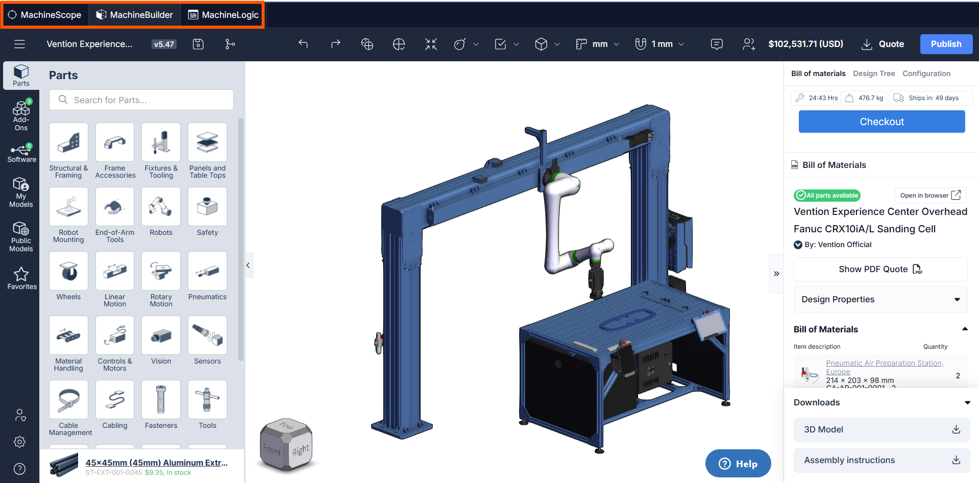
To create a new application, select the New app button from the landing page:
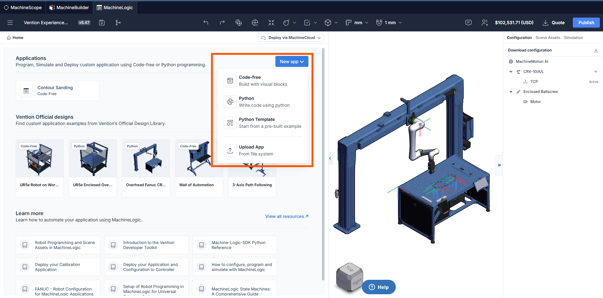
the following sections will focus on Code-Free Programming. For more information on MachineLogic Python programming, please click here
Code-free Programming
The main components of the MachineLogic Code-Free interface are explained below:
Program Assets
Variables and Functions can be defined from the Program Assets section:
.png)
Variables
Variables give the ability to change a parameter easily throughout the entirety of the MachineLogic program. This can be used to expose important application parameters such as speeds and positions, and makes it generally easier to collaborate with colleagues on the same application.
Variables support the following data type:
Integers and floats
Arrays
Strings
Objects
Json files
Variable values can be inputted directly in MachineLogic commands and changed using the Set Variable command.
It is also possible to define variables tracking input states, this can be useful when setting flags in the application that reflect the state of a configured input.
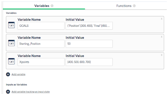 Figure 6: Variables in MachineLogic |
Functions
functions give the ability to create complex expressions to return a string, a number, an array or an object, to be inputted in other MachineLogic commands.
To use functions, enter a function name, arguments to allow names to be passed in the body and the actual Function body.
Functions accept regular JavaScript syntax, meaning for or while loops, if-else conditionals, operators, and much more can be written in the function’s body. Additionally, JavaScript objects such as Math, Array, or Map, and their respective functions can also be called directly in-line. Learn more about what can be done by visiting the official JavaScript Documentation.
functions can be called in any of the MachineLogic sequence commands found below, in the following format: FunctionName(Arguments).
Motion commands
Wait commands
Output commands
Set variable commands
Condition commands
Loop commands
Message commands
Functions should be used when similar calculations are needed to be used in the commands mentioned above. For example, if a position could be computed by adding two numbers together, it is possible to create a function that takes in two arguments and returns their sum.
Example:
First, create a function in the functions tab:
myFunction(a,b) {return a + b}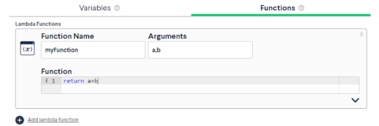 Figure 7: Creating functions |
The example below shows how functions can be inputted in a “add motion” command, in this example, myFunction(200,300) will return a value of 500.
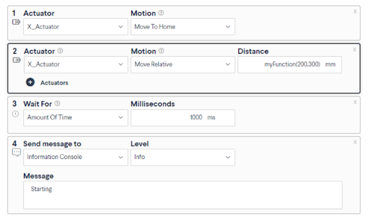 Figure 8: Calling a lambda function in a command |
Sequences
.png)
Sequences can be thought of as functions that are executed by the Main Program when using either an Execute, Condition or Loop command . Sequences contain a set of commands that will dictate a task accomplished by the machine.
New sequences can be inserted using the “Plus” icon in the header.
Sequences are displayed in a tree-view structure displaying the commands they contain. From the tree-view it is possible to duplicate instructions as well as disable them to help when debugging. Instructions can also be reordered using drag and drop.
.png)
Main Program
The Main Program is where sequences and commands are executed and simulated in the 3D View. Sequences can be executed in the main program using either Execute, Condition or Loop commands. It is also possible to directly insert commands in the Main Program.
Only one main Program may be created inside an application.
Command Pane
.png)
The Command Pane is where each of the inserted command’s properties are displayed. Commands are displayed and executed from top to bottom. It is possible to reorder commands in this view by drag and drop.
Deployment
.png)
The deployment buttons are used to access One-Click-Deploy functionalities. to learn more about deployment of your application, click here
HMI Builder
.png)
HMI Builder is a feature that can be used to create Operator Interfaces that allow interaction with the application.
to learn more about HMI builder, click here.
Run Button
.png)
Use this button to launch or interrupt the simulation
3D View
This view displays the current loaded design and enables the MachineBuilder context menu.
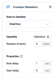
Conveyor box Mechanics can also be enabled when Conveyors are present in the design.
To enable Conveyor Simulation, select the plus icon on the associated conveyor and specify the desired simulated behavior.
Scene Assets Pane
.png)
The scene Assets pane is where robot programming Assets are displayed. To learn more about Scene Assets, click here
Simulation pane
.png)
Device Emulation:
The simulation pane allows for the emulation of IO devices and push buttons added to the design.
When these devices are configured, they will show in the simulation pane and allow interactions with the program and application when the simulation is running.
Emulation is supported for the following devices:
PushButton module
Digital I/O module
Estop Module
Estop Module W/ reset
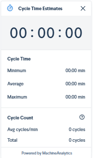
Cycle Time
The Cycle time functionality displays both cycle time and cycle count when playing a program in simulation.
To calculate cycle time, the application must contain both a MachineAnalytics Cycle Start and Cycle End events. Both commands are found in the Set Output Category.
Add Commands
.png)
The Add command button is used to access and insert commands in Sequences and Main Programs. It contains instructions cards that are used to program the logic and motion of the application.
.png)
Programming Commands
| Description |
Break from loop | Immediately exits the innermost |
Condition | Executes one of several specified sequences based on the evaluation of conditional expressions (similar to If/ElseIf/Else logic). |
Console Log | Outputs a specified message (text, variable values, or expression results) to the MachineLogic information console for debugging or status. The console is accessed through the |
Loop | Repeats the execution of a specified sequence either forever, a fixed number of times, or while a given condition remains true. |
Python snippet | Executes a user-provided block of Python code, allowing access to the MachineLogic Python SDK for custom logic. |
Run Sequence | Executes a specified, named sequence either in series (waiting for completion) or in parallel (continuing immediately). |
Set variable | Assigns a new value to a specified variable, sourced from an expression, a device input, an actuator position or a constant. |
Stop application | Immediately terminates the execution of the entire MachineLogic application. |
Wait for amount of time | Pauses the execution of the current sequence for a specified duration (e.g., in seconds or milliseconds). |
Wait for condition | Pauses the execution of the current sequence until a specified logical expression evaluates to true. |
State machine Command

Use this instruction to create state machines in your application. To learn more about State machines in MachineLogic, click here
Input/Output Commands
| Description |
set digital output value | Sets the state of a specified digital output pin to High (1) or Low (0). |
set variable from digital input state | Reads the current state (High/1 or Low/0) of a specified digital input pin and assigns that value to a Boolean variable. |
Wait for digital input state | Pauses the execution of the current sequence until a specified digital input pin reaches a desired state (High/1 or Low/0). |
wait for digital input transition | Pauses the execution of the current sequence until a specified digital input pin changes state (either rising edge: 0 to 1, or falling edge: 1 to 0). |
Communication Commands
| Description |
Make HTTP request | Sends an HTTP request (e.g., GET, POST) to a specified URL, optionally sending data and storing the server's response in a variable. |
Publish MQTT message | Publishes a message (payload) to a specified topic on the MachineLogic MQTT broker. |
Wait for MQTT message | Pauses the execution of the current sequence until a message is received on a specified MQTT topic, optionally filtering by message content. |
Send Ethernet/IP message | Sends a data packet using the EtherNet/IP protocol to a configured target device on the network. To learn more about Ethernet/IP, click here. |
Wait for Ethernet/IP | Pauses the execution of the current sequence until a specific data packet is received from a configured device via the EtherNet/IP protocol, optionally filtering by data. To learn more about Ethernet/IP, click here. |
MachineAnalytics Commands
| Description |
|---|---|
Cycle Start | Initiates the cycle timer and counter accessible through the simulation pane. |
Cycle End | Terminates the cycle timer and counter and displays the resulting cycle time. |
Robot Commands
| Description |
Robot move | Commands the robot to move its Tool Center Point (TCP) through a sequence of one or more specified targets (Cartesian or Joint Scene Assets), using defined motion parameters (Move Type, Speed, Acceleration, Blend Radius). to learn more about Scene assets, click here |
Robot move relative | Moves the robot a specified distance and/or rotation (X, Y, Z, Rx, Ry, Rz) relative to its current position, along the active TCP frame. |
Robot stop | Immediately stops any ongoing robot motion initiated by a previous |
Set Payload | Informs the robot controller of the current weight (payload in kg) being carried by the robot, allowing it to adjust dynamics for optimal performance and safety. |
Set active TCP | Selects and activates one of the pre-configured Tool Center Points (TCPs) for subsequent robot motions, allowing the program to switch between different tools or reference points. |
Linear Actuator Commands
| Description |
Move relative | Moves one or more specified linear actuators a defined distance (positive or negative) from their current positions, using the currently set motion parameters. Motion can be either in series (waiting for completion) or in parallel (continuing immediately). |
Move absolute | Moves one or more specified linear actuators to a defined position relative to their established home position, using the currently set motion parameters. Motion can be either in series (waiting for completion) or in parallel (continuing immediately). |
Move to home | Initiates the homing sequence for one or more specified linear actuators, moving them towards their home sensor to establish a zero reference point. |
Set motion parameters | Defines the maximum speed and acceleration values that will be used for subsequent motion commands ( |
set variable from actuator position | Reads the current position of a specified linear actuator and assigns that numerical value to a variable. |
Stop linear move | Immediately stops any ongoing motion for the specified linear actuator(s). |
Wait for motion complete | Pauses the execution of the current sequence until the specified linear actuator(s) have finished their current motion commands ( |
Rotary Actuator Commands
| Description |
Move relative | Rotates one or more specified rotary actuators by a defined angle (positive or negative, in degrees) from their current positions, using the currently set motion parameters. Motion can be either in series (waiting for completion) or in parallel (continuing immediately). |
Move absolute | Rotates one or more specified rotary actuators to a defined angular position (in degrees) relative to their established home position, using the currently set motion parameters. Motion can be either in series (waiting for completion) or in parallel (continuing immediately). |
Move to home | Initiates the homing sequence for one or more specified rotary actuators, moving them towards their home sensor to establish a zero-degree reference point. |
Set motion parameters | Defines the maximum angular speed (e.g., deg/s) and angular acceleration (e.g., deg/s²) values that will be used for subsequent motion commands ( |
set variable from actuator position | Reads the current angular position (in degrees) of a specified rotary actuator and assigns that numerical value to a MachineLogic variable. |
Stop rotary move | Immediately stops any ongoing rotational motion for the specified rotary actuator(s). |
Wait for motion complete | Pauses the execution of the current sequence until the specified rotary actuator(s) have finished their current rotational motion commands ( |
Move to closest angle | Rotates a rotary actuator to a specified target angle (within -360 to 360 degrees) using the shortest path, or a specified direction (clockwise/counter-clockwise), ensuring less than a full rotation. |
Set angle | Redefines the current physical position of a rotary actuator as a specific angle value (in degrees) without causing any physical movement. |
Start continuous move | Initiates continuous rotation of a specified rotary actuator at the currently set speed and acceleration until a |
Conveyor Commands
| Description |
Move relative | Moves one or more specified conveyors a defined linear distance (positive or negative) from their current positions, using the currently set motion parameters. Motion can be either in series (waiting for completion) or in parallel (continuing immediately). |
Set motion parameters | Defines the maximum linear speed (e.g., mm/s) and linear acceleration (e.g., mm/s²) values that will be used for subsequent motion commands ( |
set variable from actuator position | Reads the current estimated linear position of a specified conveyor (if position tracking is enabled/supported) and assigns that numerical value to a variable. |
Stop conveyor move | Immediately stops any ongoing motion for the specified conveyor(s), including continuous moves. |
Wait for motion complete | Pauses the execution of the current sequence until the specified conveyor(s) have finished their current discrete motion commands (e.g., |
Start continuous move | Initiates continuous forward or reverse motion of a specified conveyor at the currently set speed and acceleration until a |
Pneumatic Commands
| Description |
Push | Activates the output associated with extending the piston of the specified pneumatic actuator. |
Pull | Activates the output associated with retracting the piston of the specified pneumatic actuator. |
Idle | Deactivates both the push and pull outputs for the specified pneumatic actuator, allowing it to potentially be moved freely by external forces. |