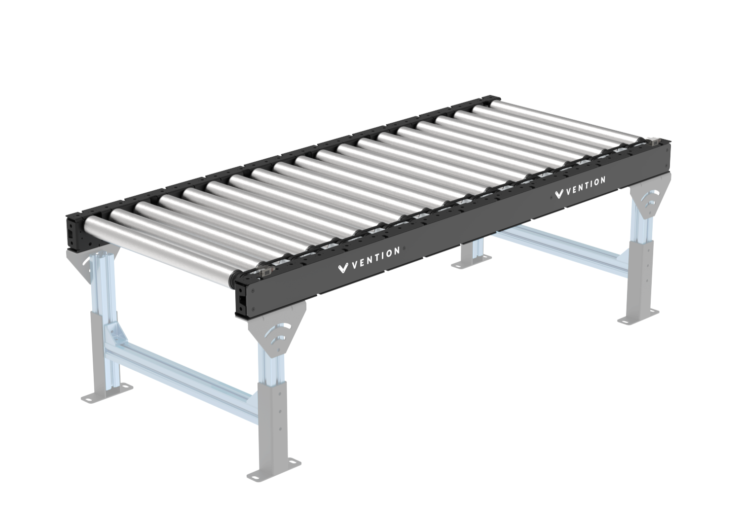
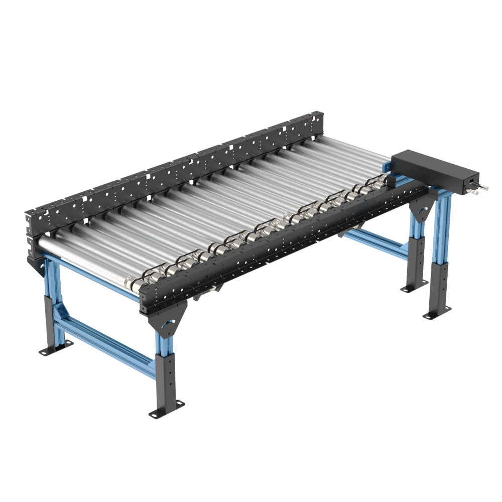
Vention’s pre-assembled poly-v roller conveyor sections were designed to ensure an easy initial setup and long-lasting performance. From a simple straight segment to a full conveyor application, it has never been so easy to design a conveyor system. All our sections are compatible with each other, as well as our full Vention’s ecosystem.
All sections are equipped with provisions to add sensors and cable management cut-outs and are compatible with many Vention accessories, including modules, leg adjustment, angle adjustment, pneumatic pushers, and end stops.
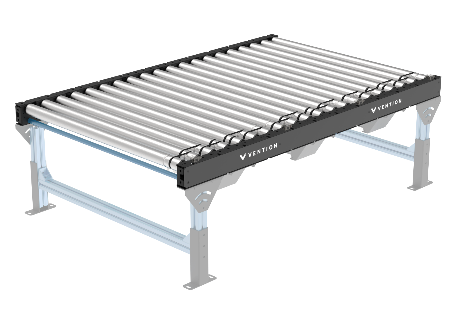
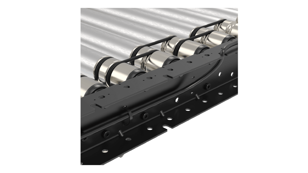
Straight sections
Our straight sections are available in 2 widths (585 and 945 mm) and a length of 1575 mm. These sections come unpowered and the Motor Mount Bracket (MO-CV-031-0006) and Motor Adaptor (MO-CV-039-0001) can be added to them as required. This is because two segments can be powered by a common motor at their junction.
Table below shows all variations of straight sections.
Note: Width is the between the frames width (BF width) of the rollers. For the full width of the conveyor add another 90mm.
|
|
Part Number | Width (mm) | Length (mm) | Number of rollers |
|---|---|---|---|
585 | 1575 | 20 | |
945 |
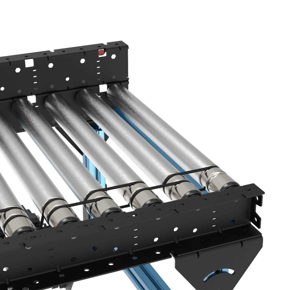
Skewed sections
Vention’s new Poly-V conveyor family includes a series of skewed sections designed to align packages against a conveyor guide while supporting accumulation. This allows boxes to be consolidated on one side of the conveyor and buffered until a full group has formed, an ideal setup for end-of-line palletizing. Additionally, these rollers feature accumulation sleeves that increase buffer capacity and extend the equipment's service life. All four sections are available in left- and right-hand configurations.
|
|
.png)
.png)
Part Number | Width (mm) | Direction | Length (mm) | Number of Rollers | Skewed Angle (°) | Lateral Movement Along Length (mm) |
|---|---|---|---|---|---|---|
405 | Right to Left | 1575 | 19 | 10.8 | 300 | |
Left to Right | ||||||
585 | Right to Left | 7.6 | 210 | |||
Left to Right |
Applications
Conveyors are used to move loads from one point to another. Our poly-v conveyor family offers possibilities to create applications that vary from material transport to accumulation. Visit our design library for sample designs of different applications. Here are a few examples:
To build a conveyor using our Machine Logic code-free conveyor application, consult this guide.
Material Transport
The Poly-V Roller Conveyor is engineered for the high-capacity transport of diverse industrial goods, including boxes, totes, and full pallets. Designed for heavy-duty applications, the system supports a maximum payload of up to 500 kg.
For complex floor layouts, Poly-V sections can be seamlessly integrated with O-ring conveyors to facilitate 90-degree turns and corner transitions. Additionally, the system is compatible with smart zone sections for zero-pressure accumulation (ZPA) functionality. Note that while these smart zones enable precise part sequencing and indexing, they operate with a reduced maximum payload compared to standard heavy-duty Poly-V segments.
Accumulation for end-of line packaging
In end-of-line packaging environments, the Poly-V Roller Conveyor provides a robust solution for pressure accumulation. This configuration is specifically designed to buffer boxes and other goods, creating a stable, repeatable queue for high-precision picking by industrial or collaborative robots (cobots).
This setup is especially advantageous for multi-pick configurations. By allowing goods to accumulate against a stop, the system automatically aligns and positions multiple boxes simultaneously. This enables a robotic gripper to "multi-pick"—grabbing several units in a single cycle—significantly increasing the throughput of palletizing or case-packing operations.
Technical Note: To maintain optimal system health and ensure maximum belt longevity, the payload limit for pressure accumulation applications is 30 kg. This restriction minimizes frictional heat and mechanical stress on the Poly-V belts during continuous accumulation, preventing premature wear while maintaining high-density staging for robotic integration.
Technical Specifications
Section types | straight, skewed |
Application type | conveying, accumulation |
Lengths | 1575 mm |
Roller diameter | 50 mm |
Rollers Pitch | 78.75 mm |
Roller widths (mm) | 405, 585, 945 mm |
Between frame width (BF) (mm) | 405, 585, 945 mm |
Max payload for transport (Rigid container such as crate or tote)* | 500 kg |
Max payload for transport (cardboard boxes)* | 150 kg |
Max payload for pressure accumulation | 30 kg |
Max payload per roller | 40 kg |
Max speed | 2000 mm/s |
Displacement ratio | 120.8 mm/revolution |
Min box length | 160 mm |
Roller material | zinc plated steel |
*Note: The capacity to transport material is highly dependent on the rigidity of the payload and therefore the generated rolling resistance. A rigid plastic tote bin or wooded box or pallet will yield much higher load capacity than a single layer cardboard box. For example the conveyance of wooden pallet or totes weighing up to 500kg is possible but when using carboard boxes a limit of 150kg per zone should be used. A zone is defined as a grouping of rollers or conveyors driven by a common motor.
Accessories
1) Leg adjustments
The two following leg and conveyor adjustments are available and fully compatible with this o-ring conveyor family.
Height Adjustment bracket: This bracket allows a quick and simple way to adjust the conveyor to any existing equipment. The max translation is 150 mm
Angle Adjustment bracket: The angle adjustment bracket is a key part for all gravity conveyors, while also allowing to adjust the conveyor to existing equipment.
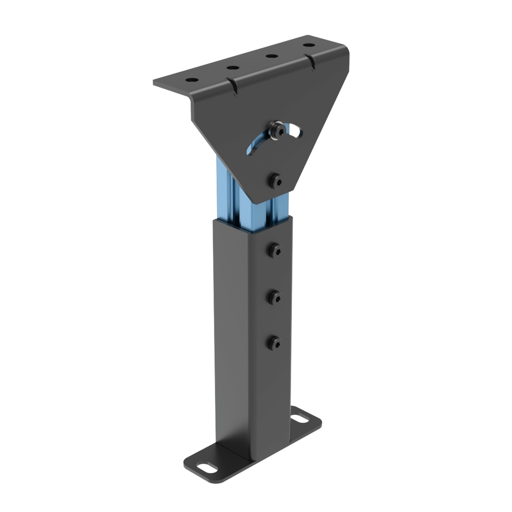
Height and angle adjustments
2) Modules, sensors, and cable management
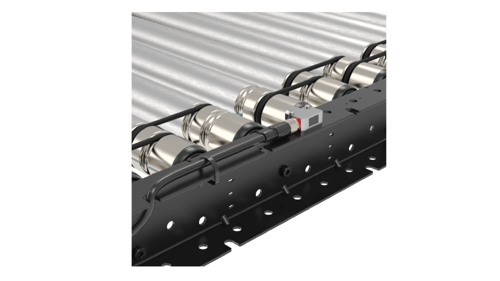
Sensor Mounts
Each C-channel of Vention’s Poly-V conveyor family is equipped with specific placement for sensors, making it easy to install without additional hardware. It is also possible to use any existing hole, with the addition of the sensor bracket (CE-HW-001-0003).
I/O and E-Stop Module
There are several options for installing the I/O and E-Stop modules, either using the vertical extrusions or using a simple extrusion structure attached beneath the conveyor c-channel, as shown below.
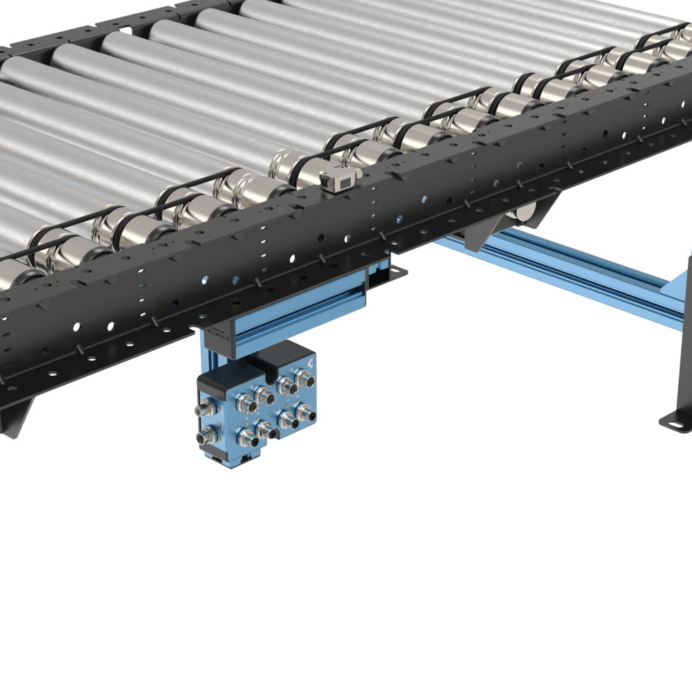 Module and sensor installation |
Cable Management
The C-Channel brackets is equipped with cutouts to allow easy cable management coming from sensors, modules, and motor cables to prevent chaffing and offer a clean integration setup. It is also possible to use zip ties to secure cables using the designated holes along the C-Channel.
|
|
3) Guides
a) Mounting bracket as side guard
The C-channels mounting the rollers are versatile and can also be used as a guiding system on all sections. The c-channel can simply be superposed over the actual conveyor section. Associated fasteners are included in each C-Channel to ensure a safe installation.
.png) Straight mounting bracket as side guide | 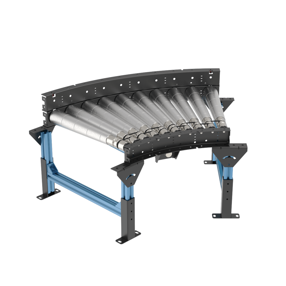 Curve mounting bracket as side guard |
Another great perk of having a channel as a side guide is being able to install sensors underneath the top bracket in its designated cutouts. This will allow maximum protection of the sensor.
 Sensor behind guard | 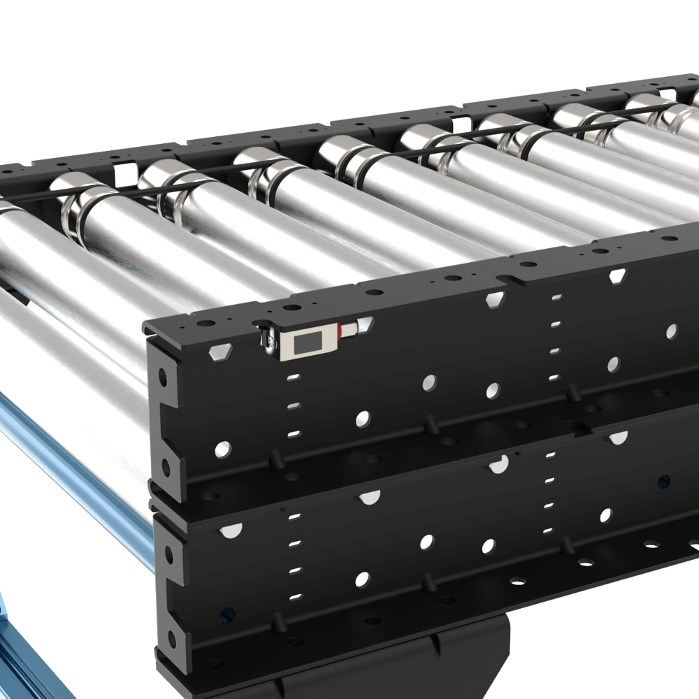 Sensor behind guard (other side) |
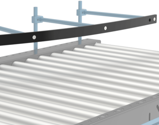
b) Flexible guides (straight sections only)
Flexible guards (ST-PN-020-XXXX) come in multiple lengths and can be cut to specific lengths if needed. They are used to index or funnel boxes along a conveyor during material handling operations. Using our well-known round extrusion, the flexible guide provides an adjustable solution for flexible guide. For more details, refer to the Flexible Conveyor Guide section of the Material Handling Datasheet.
4) Pneumatic pushers
In palletizing applications, to have the box on a certain location on the conveyor at the end of the line and close to the robot to pick up, a pneumatic pusher is used to push the box to the side of the conveyor. It is possible to install the pneumatic pusher in a simple way on Vention’s new poly-v conveyors. Follow these steps for a quick and easy design:
Install a short 45x45 extrusion on top of the conveyor c-channel using associated fasteners from the conveyor
M8 serrated nuts (HW-FN-031-0002)
M8x18 mm screws (HW-FN-003-0018) and
M8 split washers (HW-WS-001-1003)
Design and install an additional leg made of extrusion, with the same height as the conveyor. The below image shows a T-shaped leg to hold the pusher.
Install the pusher on top of the conveyor and the additional leg.
Pneumatic pusher installation
Pinch Point Mitigation
The driving system in the poly-v conveyors is a high tension transmission belt. This means that much more torque is transmitted to the rollers, therefore higher dangers and risks of pinch points and entrapments are relevant for this drive type.
To mitigate these risks and offer an inherently safe solution, Vention has implemented numerous guards and protective features directly into the ecosystem so that no external components are needed to make your conveyor system safe.
Some or all of these guards may be needed depending on the level of protection required and depending on factors such as a safety fencing solution or if the conveyor is accessible to operators while running. If the conveyor is in a fenced enclosure and inaccessible to operators while running then none of these solutions are needed. Both casses are supported by Vention.
Finger guards:
To prevent any pinch points or entrapments with the belts, plastic guards that reduce all gaps to the belts to less than 5mm are installed on all of the poly-v conveyors. These guards prevent pinches and entrapment by shrinking the gaps and openings between the moving belt and other components to a size smaller than what can be pinched. This is in line with standards such as ANSI/ASME B20.1, ISO 13857, and OSHA 1910.219.
Note: The finger guards are installed with 1Nm, if they are removed to replace a belt or roller do not over torque them upon re-installing.
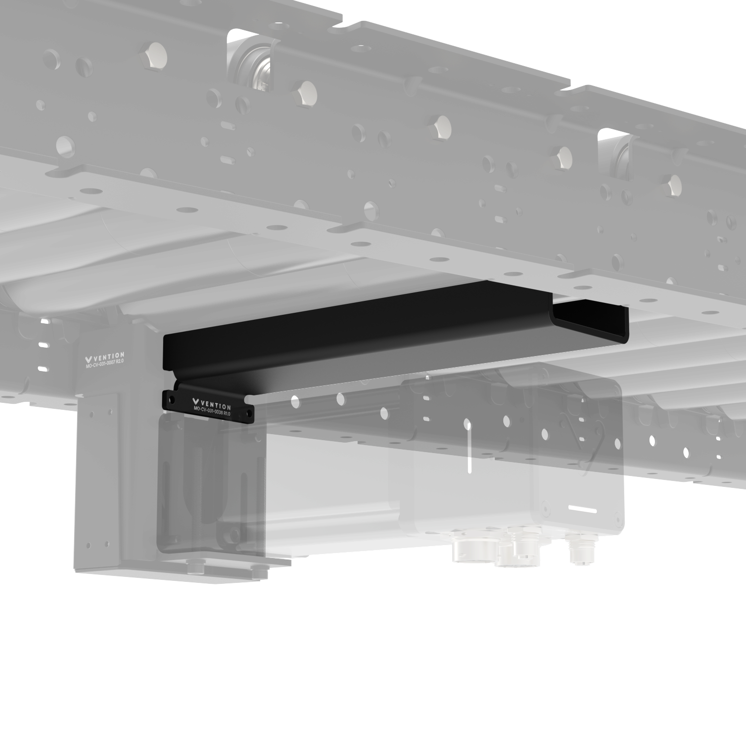
Motor Mount Covers:
The motor mounts of the poly-v ecosystem have been designed to mitigate all access to the drive belts when combined with the motor shaft cover (shown in transparency below).
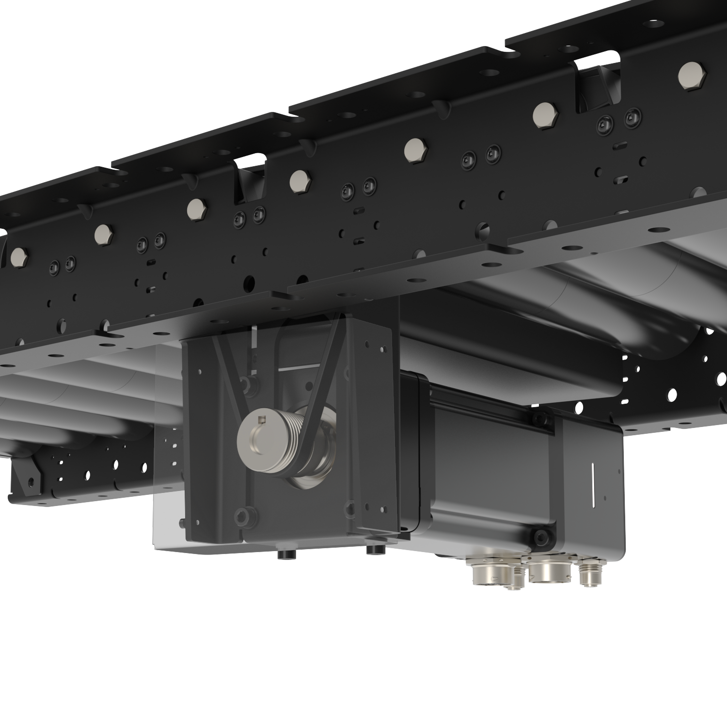
To prevent a pinch point between the motor body and the underside of the rollers a motor, the roller-motor guard (MO-CV-031-0038) was created.
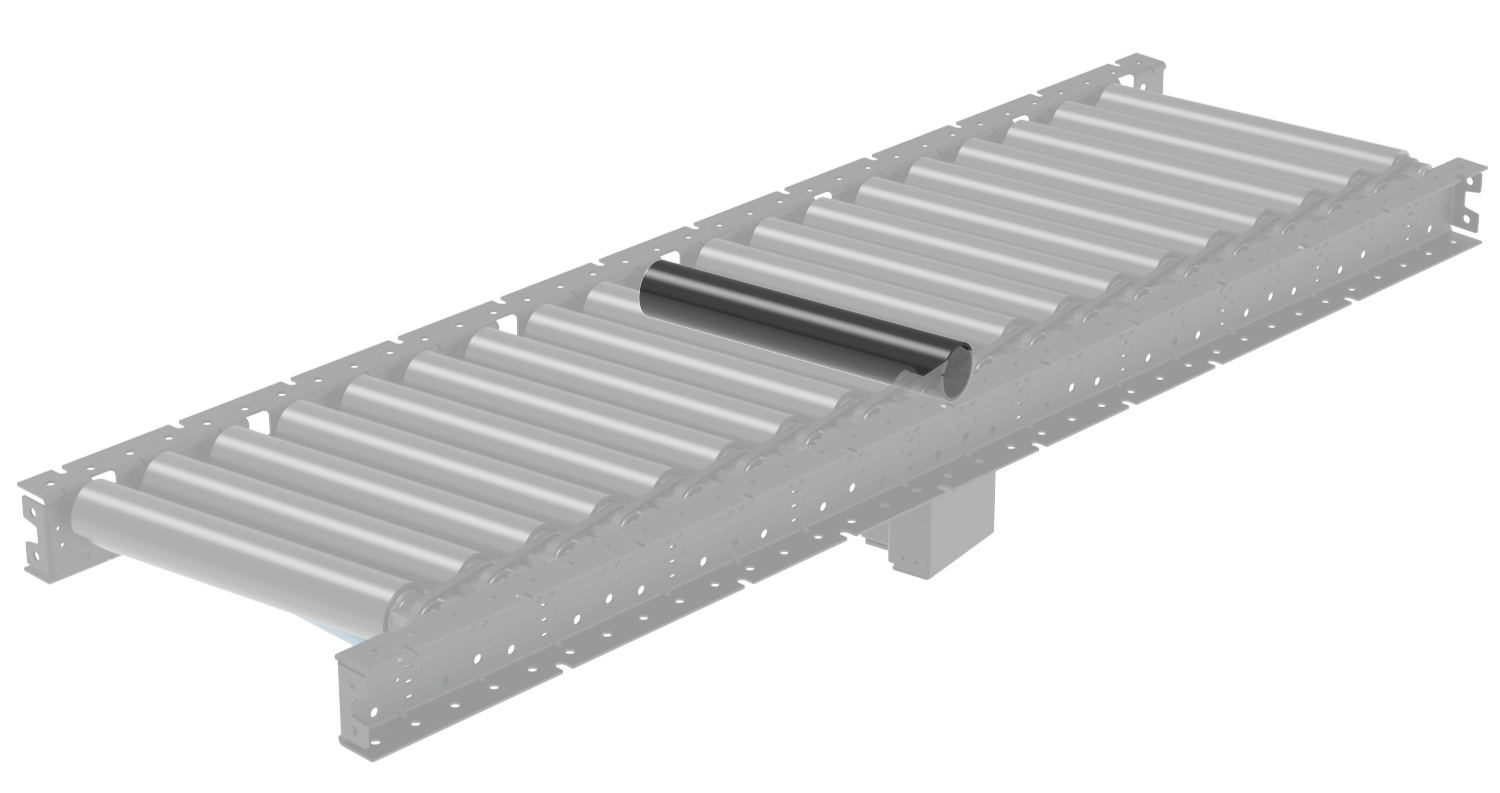
Frame Bracing:
The blue round extrusions that ship with our conveyors are used to connect the left and right sides of the conveyor as bracing. These round extrusions can form a pinch point with the underside of the rollers. Note that this is only an issue when the rollers are not equipped with the accumulation sleeves as the sleeves very easily slide on the outside of the roller, preventing entrapment and pinch points by not transferring the roller torque to the operator.
In cases where no sleeve is present this is a known pinch point. The support legs for the conveyor can be designed with sufficient cross bracing to support the conveyor laterally. In such cases the extrusions can be completely removed and the pinch point eliminated. Any bracing placed under the rollers must be spaced at least 120mm from the underside of the roller to avoid creating a pinch point.
.png)
Roller Sleeves
As hinted at in the previous section, the conveyor sleeves add safety to the poly-v drive system by introducing an intentional slip point between the inner diameter of the sleeve and the outer diameter of the rollers. This prevents the transmission of force and torque of the poly-v drive to the user, thereby removing the pinch points between the rollers and surrounding components.
Infeed/Outfeed Gap Covers for Skewed Conveyors
When a skewed section of conveyor ends or meets a straight section, there is naturally a large gap to fill at the end of the conveyor. To fill this gap and remain pinch point free the infeed and outfeed gap covers have been created.
These covers also include a small passive roller to enable payload movement across the cover.
Gap Covers for Straight Conveyors
Any point on the poly-v conveyor system that has a conveyor segment end, it is important to consider pinch points at the adjacent structure since the last roller may be moving while a static object within proximity may create a pinch point.
To address this issue the infeed/outfeed gap cover for straight conveyors is used. It envelopes the last roller so that no gap greater than 5mm is present around the moving object.
Use this guard at transitions from separate poly-v zones, straight to skewed transitions, T junctions, end stops, and other relevant configurations
Assembly Instructions
Assembling the legs, anchoring, sensor installation and butt-joining conveyors are all same as our smart o-ring conveyor. Please refer to Assembly Instruction of smart o-ring conveyor for those. The following installation instructions are exclusively for poly-v conveyors.
1) Installing the motor mount and driver belt
Place the motor adaptor at the highest position and use four M6x18mm (HW-FN-005-1018) and four M6 washers (HW-WS-005-0001) to attach it to the motor mount of the conveyor.
.png)
Note 1: Do not fully tighten them at this stage.
Note 2: When installing the motor adaptor on the motor mount of the conveyor, the two M6 threaded holes on the side of the motor adaptor must be facing down (towards the ground) for tensioning in the next step.
Use two M6x70mm (HW-FN-005-1070) and two M6 washers (HW-WS-005-0001) at the location shown below on the Motor Mount (MO-CV-030-0008) and connect the screws to the threaded holes on the bottom of Motor Adaptor (MO-CV-029-0001).
.png)
Lower the 2 hanging poly-v belts onto the grooved shaft of the motor adaptor.
While having the four screws on the Motor Mount (MO-CV-030-0008) slots still loose, use the two M6x70mm (HW-FN-005-1070) screws to bring down the motor adaptor. The motor adaptor will slide down and create tension in the poly-v belts on the shaft. The tension for the 70mm long M6 tensioning bolts should be 4-5Nm.
Check that the alignment of the belt is straight and the poly-v belt is in the correct grooves on both the roller and the motor pulley.
When the motor mount is in its final position on the vertical slots, tighten the four M6x18mm screws (HW-FN-005-1018) to 9 -11 N.m.
2)Skewed sections cover Brackets
For covering the end gaps of skewed conveyors, a cover bracket and a smaller grooved roller can be installed at both ends of the conveyor. Table below shows the compatible cover bracket part numbers with each of the skewed conveyors.
Skewed Conveyor | Width (mm) | Direction | Compatible Cover Bracket | Associated Small Roller |
|---|---|---|---|---|
405 | Right to Left | MO-CV-031-0017__2 | MO-CV-001-0135 | |
MO-CV-031-0019__2 | ||||
Left to Right | MO-CV-031-0018__2 | |||
MO-CV-031-0020__2 | ||||
585 | Right to Left | MO-CV-031-0021__2 | MO-CV-001-0180 | |
MO-CV-031-0023__2 | ||||
Left to Right | MO-CV-031-0022__2 | |||
MO-CV-031-0024__2 |
Cover Bracket Installation
Place the cover bracket between the c-channels of the conveyor, parallel to the rollers, and connect it to the conveyor using the following associated fasteners. Torque the M8 screws to 15-18 N.m.
2x M8x18 mm screws (HW-FN-003-0018)
2x M8 split washers (HW-WS-001-1003)
2x M8 serrated nuts (HW-FN-031-0002)
Place the small roller (MO-CV-001-0135/0180) inside the cover into the shown location by inserting in the hex shaft of the small roller into the hex hole of the conveyor and then pressing the other side of the spring-loaded shaft into the hex hole of the cover bracket.
Note: The installation process is similar to all skewed configurations.
3) Motor shaft cover installation
Install the Motor Shaft Cover (MO-CV-031-0016) on the Motor Mount Bracket (MO-CV-031-0006) using the following associated fasteners. Torque the M3 screws to 1.2-1.4 N.m.
4x M3×6 mm screws (CE-FN-003-0006)
4x M3 split washers (CE-WS-003-0005)
.png)
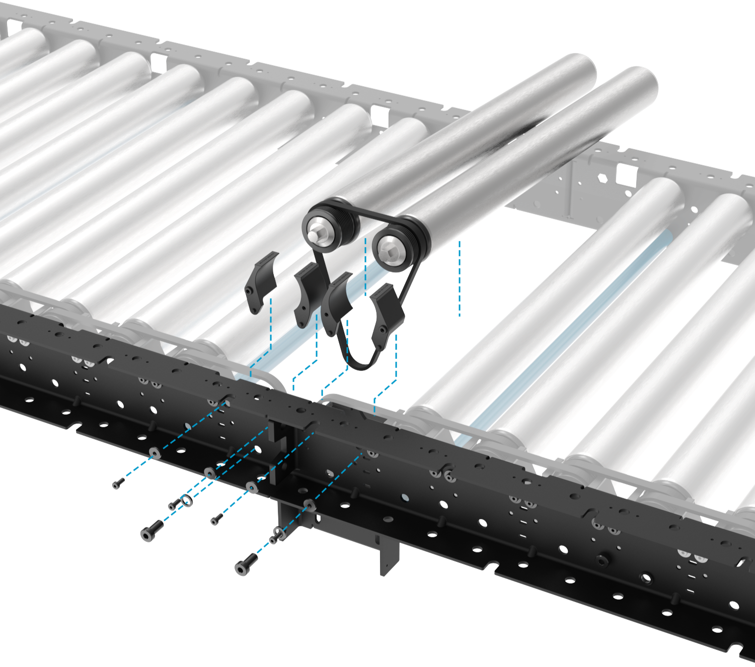
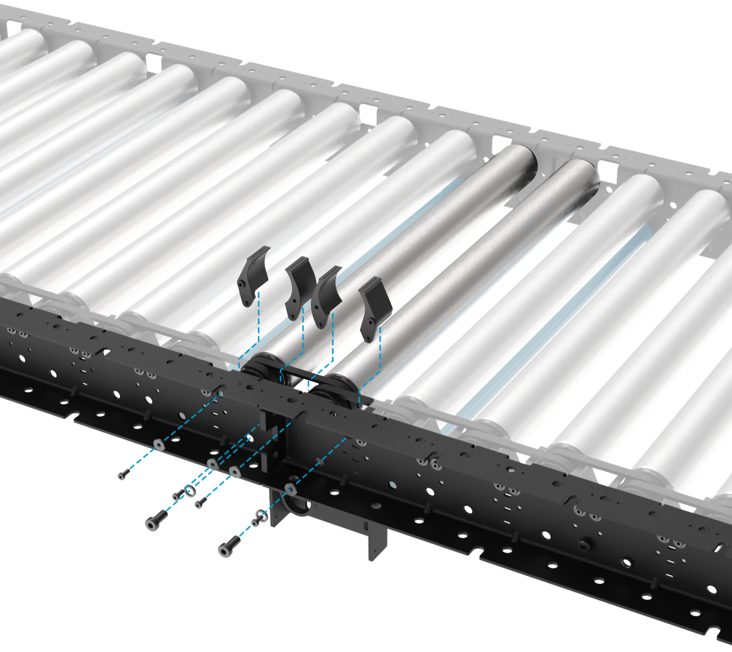
4) Installation of a Motor Mount Between Two Unpowered Poly-V Conveyors
Two unpowered poly-v conveyors can be transformed to powered units by installing a motor on the segment. The motor can be installed at the intersection of two segments to join them together as a single zone for material transport. This configuration is maximum number of rollers driven by a single motor with 20 rollers on either side of the motor.
To begin, merge the two conveyors together. Once attached you may begin the installation of MO-CV-031-0006__2. The motor mount assembly will come with the drive belt, the mount, the appropriate finger guards, and all mounting hardware.
|
|
.png)
Screw the sheet metal motor mount into the extrusion c-channel then install the rollers and belt. Torque the M8 bolts to 13-15Nm.
Next, install the finger guards using the included M4 fasteners and washers. Note that the two finger guards in the middle will have a different texture and also the fastener hole is a self-tapped plastic thread instead of the brass inserts in the other units. From left to right the part numbers of the finger guards are MO-CV-031-0028__2, MO-CV-031-0026__2, MO-CV-031-0025__2, MO-CV-031-0027__2. All of the M4 fasteners should be torqued to 1Nm.
.png)
Finally, mount and tension the motor mount adaptor so that it is all of the way at the bottom of the tensioning slots. Refer to 1) Installing the motor mount and driver belt for more detailed instructions
.png)
Maintenance and Support
1- Maintenance
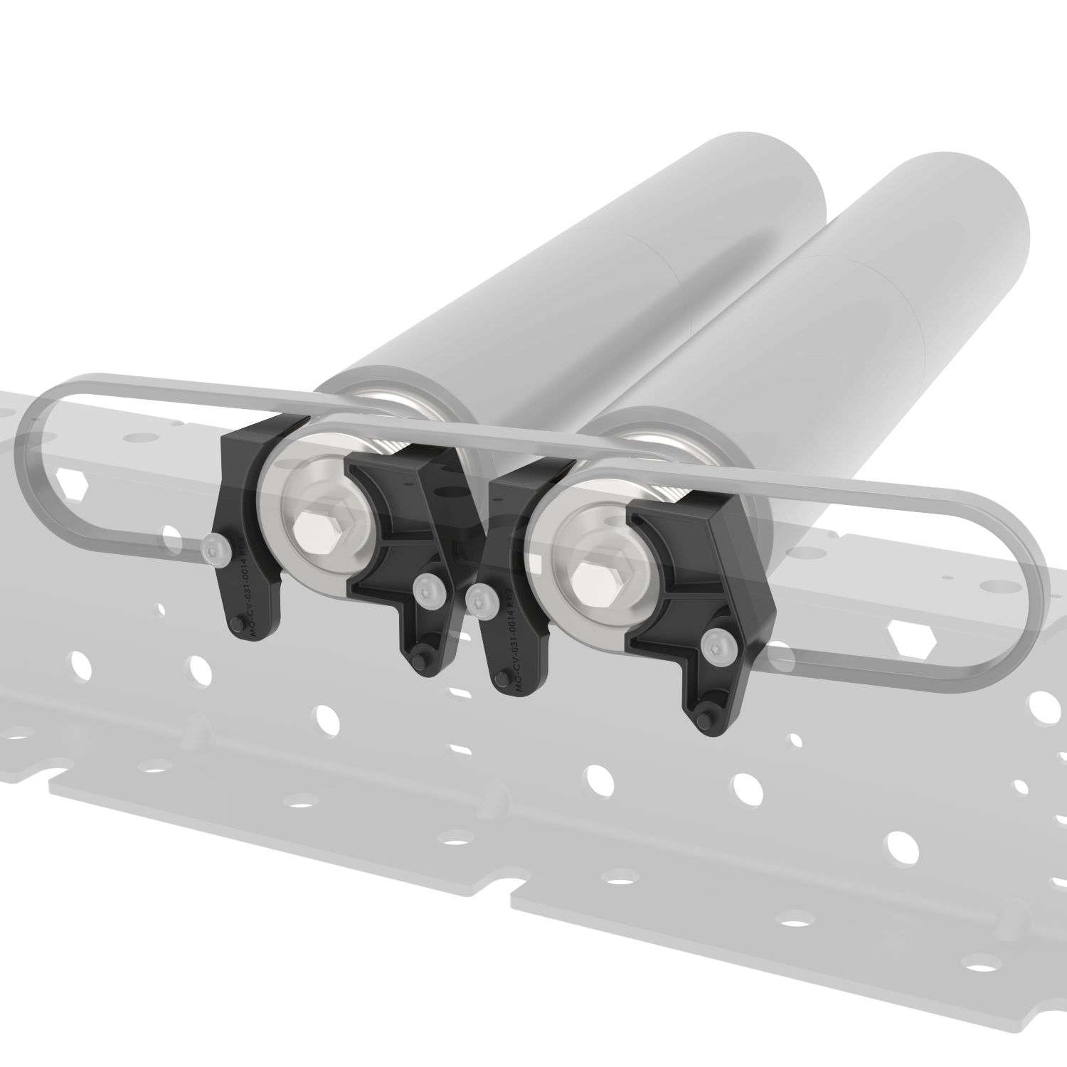
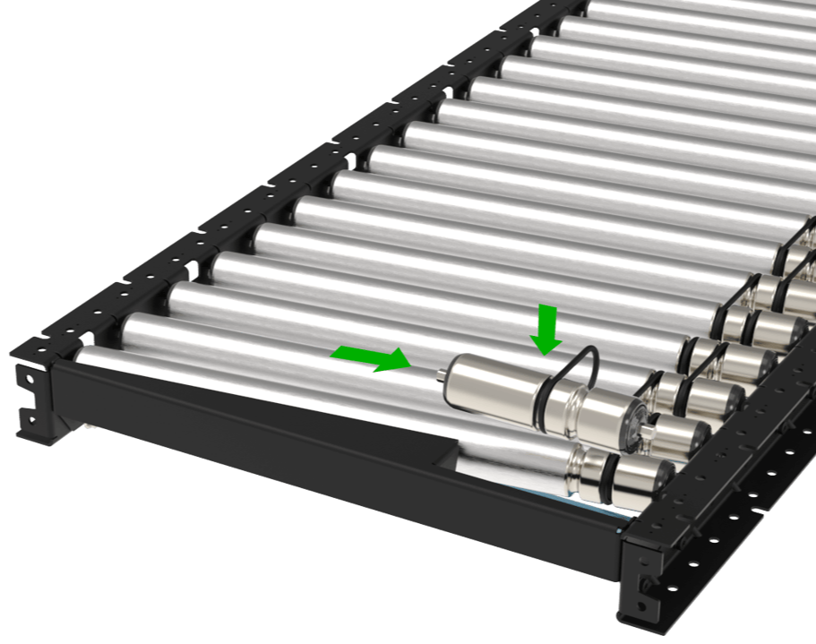
In case of failed poly-v belts, identify which side of the failed belt is closer to the start or end of a zone as all of the rollers will need to be removed. To remove the rollers, follow these steps:
Cut the failed poly-v belt if it is not already broken.
Uninstall the surrounding finger guards. The screws are M4s with washers.
Push in the spring-loaded hex shaft of the belt side of the rollers and remove all of the rollers between the end or beginning of the zone and the affected belt (green arrow).
Put the good belts to the side to be reused when reinstalled
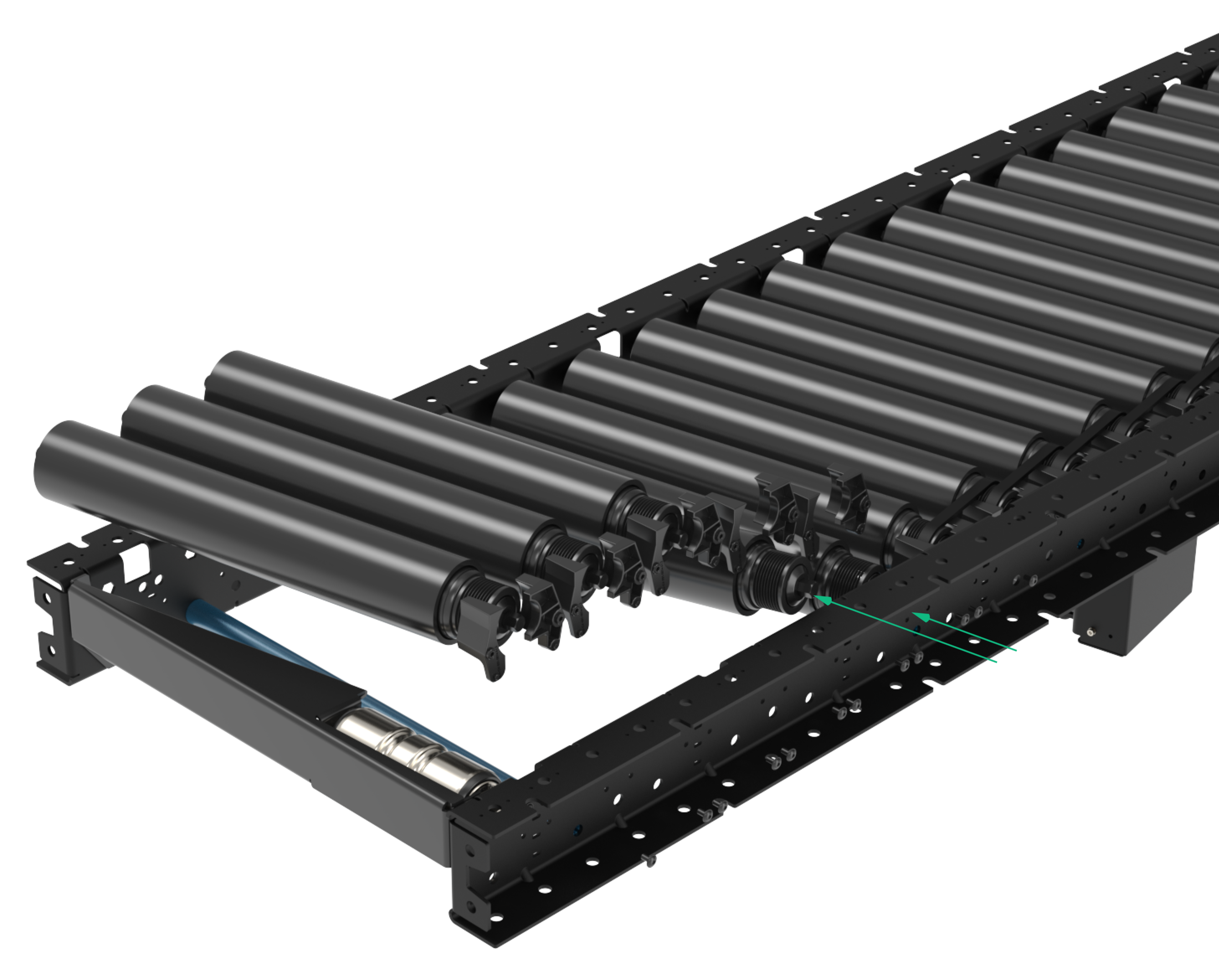
Install the new belt and begin re-installing the roller into the c-channel. Use Vention’s roller installer tool (HW-TL-004-0002__2) to place the roller hex shaft back in the hex hole.
Repeat step 5 for all of the rollers that were removed.
Re-install all of the finger guards.
Double check that all of the belts are in the proper groves and they are not rubbing on each other.
Poly-V Belt | Note |
|---|---|
Used for roller to roller connection in straight and skewed sections | |
Used for Conveyor Roller to Motor Adaptor Pulley |
Troubleshooting
1- Troubleshooting
The table below lists common issues/errors that may occur during operation of the Poly-V Roller Conveyor system, their possible causes, and recommended corrective actions.
Issue / Error | Possible Causes | Actions |
|---|---|---|
Conveyor does not start / motor does not run |
|
|
Rollers spin but belt does not move / slips on rollers |
|
|
Conveyor speed is incorrect or inconsistent |
|
|
Unusual noise during operation (squealing, grinding, or rattling) |
|
|
Boxes not accumulating correctly on skewed sections |
|
|
Sensor not detecting product / false triggers |
|
|